
Contact jcamachocsices Access to provided data and code The provided data set contains a circular scan of the tissue mimicking phantom depicted in Fig 1 based on water gelatin graphite powder and alco ID: 870584
Download Pdf The PPT/PDF document "Multimodal Ultrasound Breast Imaging Sys..." is the property of its rightful owner. Permission is granted to download and print the materials on this web site for personal, non-commercial use only, and to display it on your personal computer provided you do not modify the materials and that you retain all copyright notices contained in the materials. By downloading content from our website, you accept the terms of this agreement.


1 Multimodal Ultrasound Breast Imaging Sys
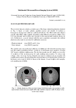
Multimodal Ultrasound Breast Imaging System (MUBI) Ultrasound Systems and Technology Group, Spanish National Research Council (USTG-CSIC) Group of Nuclear Physics, Complutense University of Madrid (GFN-UCM) Contact: j.camacho@csic.es Access to provided data and code The provided data set contains a circular scan of the tissue mimicking phantom depicted in Fig. 1, based on water, gelatin, graphite powder and alcohol. It includes a homogenous background with two cylindrical hollows: One filled with water (black) and the other filled with a gelatin preparation with different proportions (white). Two 0.25 mm diameter steel needles were inserted in the approximate locations shown (in red). Furthermore, a second dataset with the same acquisition parameters but without phantom (only water) is provided for calibration purposes: - Phantom dataset: tom_050815_ph15_1.zip- Water dataset: tom_050815_agua.zipThe circular scan was performed with two 3.5 MHz and 128 elements moving arrays (see the system description below). A total of 23 fan-beams were acquired, covering 360º degrees with the emitting array. The fan-beam angle was 80º, which is covered by 11 positions of the receiving array for each emitting array position. To reduce data volume, only 1 of every 8 array elements was used in emission and in reception (16 equally spaced active elements along the arrays apertures), producing 2816 A-Scans per fan-beam, and a total of 45056 A-Scans in the dataset. A-scan length is 600 samples, and sampling rate 40 MHz. Fig. 1 Gelatin phantom of the provided dataset (left) Schematic representation with approximate dimensions and (right) full angle spatial compound with 36 phased-array sector-scan images. needles System description The Multimodal Ultrasound Breast Imaging System (MUBI) is a joint development of the Spanish National Research Council (CISC) and the Complutense University of Madrid (UCM), under
2 the projects ARTEMIS [1] and TOPUS [2].![the projects ARTEMIS [1] and TOPUS [2].](870584/the-projects-artemis-1-and-topus-2-it-is.jpg "the projects ARTEMIS [1] and TOPUS [2].")
the projects ARTEMIS [1] and TOPUS [2]. It is intended to be a flexible platform for multi-modal ultrasound imaging research, mainly oriented to breast diagnosis [3]. Up to now, the following imaging techniques have been implemented: Phased-Array full angle spatial compound (FASC) [4]. Acoustic Radiation Force Imaging (ARFI) full angle spatial compound [5]. Ultrasound Computed Tomography (USCT) speed of sound and attenuation reconstruction [6-8]. The system is depicted in Fig. 2. It is formed by two 3.5 MHz, 128 elements and 0.22 mm pitch arrays (P2-4/30EP, Prosonic, Korea) that rotate with 95 mm radius into a water tank, controlled by independent stepper motors with an angular resolution of 0.1º. A 128 channel full parallel ultrasound system (SITAU-112, Dasel, Spain) is used for excitation and signal acquisition. While only one array can be used as emitter, both of them can act as receivers, allowing pulse-echo and through-transmission operation modes. The system is able to perform emission and reception beamforming in real-time (useful for implementing image compounding algorithms) and also gives access to the individual signals received by each array element (useful for USCT reconstruction). Finally, a standard personal computer controls the motors movement and the ultrasound equipment with Matlab scripts. Videos of the system working can be seen here: https://youtu.be/wrUni5JfQSE , https://youtu.be/f5nwNqZV9yc . Fig 2. MUBI system (left) schematic representation and (right) picture. The acquisition scheme for USCT follows the Fan-Beam approach of CT systems (Fig. 3). For each emitter array position, the receiving array is sequentially moved to cover an angle (Fan-Beam angle) opposite to the emitter. For each position of the receiver, all (or a subset) of the emitter array elements are sequentially fired, and the signals received by all (or a subset) of the receiving array elements are re
3 gistered. Then, the emitter array is mov
gistered. Then, the emitter array is moved and the fan-beam acquisition is repeated. The central region where all the fan-beams overlap is determined by , being the zone where better reconstruction quality can be expected (Fig. 4). Stepper motor drivers USB 2.0 Computer SITAU 112 E/R R USB USB Motor Motor Worm Worm Array Array Wheel Fig 3. Fan-Beam acquisition scheme: For each emitter array position (red), the receiving array is moved to cover an angle from the emitter center. At each receiver position, all (or a subset) of the emitter array elements are sequentially fired and the signals received by all (or a subset) of the array elements are registered. Fig. 4. After acquiring a Fan-Beam, the emitter is moved and the process is repeated (receiving array not shown in the figure). The fan-beam angle determines the size of the overlap region. Emitter Pos. 1 Emitter Pos. 2 Emitter Pos. 3 Full overlap region Emitter Fan-Beam Angle () Receiver (Position 2) Receiver (Position 1) Receiver (Position 3) Description of files and variables Each acquisition is provided in a .zip file, which contains a Fan-BeamXX.matfile for each acquired fan-beam (23 in this case). The 2816 A-Scans of each fan-beam are stored in the variable Ascans_rx with size 11 x 16 x 16 x 600, and indexed according to Ascans_rx = { Receiver array position, Emitting element, Receiving element, Samples } For example, the signal received by element 9 of the receiving array when located in the th position of the fan-beam and when emitting with element 1 of the emission array, is retrieved by ascan = AScans_rx ( 5 , 1 , 2 , : ); Notice that the AScans_rx variable only stores the signals registered with the active elements, in this case, 1 of every 8 real array elements. That is why the index to the real array element nº 9 is 2 (the second active element) when indexing the AScans_rxvariable. The variables act
4 ivos_tx and activos_rx in the parametros
ivos_tx and activos_rx in the parametros.mat file contains the emitter and receiving active elements for each array, respectively. For reducing the dataset size, acquisition start is delayed with regard to the excitation instant to discard the samples generated long before the pulse arrives to the receiving element. Delays are calculated for each emitter-receiver pair based on the calibrated speed of sound in water (included in file meas_c.mat) and their known separation, and a security factor is applied to be sure that the first arriving signal is always registered. Acquisition start instant (measured in microseconds) is stored for each emitter-receiver pair in the variable tdlr_sitau (in parametros.mat, with size 11 x 16 x 16, and indexed by tdlr_sitau = { Receiver array position, Emitting element, Receiving element } Spatial coordinates of the elements are stored in the variables coordenadas in each fan-beam file, with size 11 x 16 x 16 x 2 x 2. It is indexed in the following way coordenadas = { Receiver array position, Emitting element, Receiving element, ... ... Emitter|Receiver (1|2), X|Y (1|2) } For example, the X coordinate of the element 9 of the receiving array when located in the 5th position of the fan-beam and when emitting with element 1 of the emission array, is retrieved by x_receptor = coordenadas ( 5 , 1 , 2 , 2 , 1 ); The script LoadExample.m loads and plots all signals and describes the rest of variables in the archives, and can be used as a starting point for data processing. Also the script SaveRaw is provided, to generate raw files with the minimum necessary information for USCT reconstruction in only two files, useful to interact with reconstruction codes written in other languages different from Matlab. The file coordinates.txt gives the coordinates of all emitter- receptor pairs, and the file time_series.raw contains all the acquired signa
5 ls with zero padding to compensate the a
ls with zero padding to compensate the acquisition delay and truncated to 3000 samples (These A-Scans starts at the emission instant). License The provided MUBI USCT data is freely available dual licensed under the 3-clause BSD-license and the Open Data Commons Attribution License, requiring only acknowledgment / attribution . References [1] ARTEMIS project Advanced Real-TimE Multimodality Medical Imaging, Comunidad de Madrid, S2009/DPI-1802. [2] TOPUS project Positron emission and ultrasound tomograpy, Comunidad de Madrid, S2013/MIT-3024. [3] J. Camacho, L. Medina, J.F. Cruza, J.M. Moreno, C. Fritsch, "Multimodal ultrasonic imaging for breast cancer detection" Archives of Acoustics, 37-3, 253-260, 2012. [4] L. Medina, J. Camacho, C. Fritsch, "A characterization of ultrasonic full angle spatial compounding as a possible alternative for breast cancer screening" Archives of Acoustics, 40, 3, 301-310, 2015. [5] Nuria González-Salido, Luis Medina, Jorge Camacho, "Full angle spatial compound of ARFI images for breast cancer detection", Ultrasonics, 71, 161-171, 2016. [6] M. Perez-Liva, J.L. Herraiz, E. Miller, B.T. Cox, B.E. Treeby, J.M. Udías. "Sound speed reconstruction in full wave ultrasound computer tomography for breast cancer detection" Radiotherapy and Oncology, vol 119, pp. S454-S455, 2016. [7] M. Pérez-Liva, J. L. Herraiz, N. González-Salido, L. Medina-Valdés, J. Camacho, C. Fritch, J.M. Udías Ultrasound Computed Tomography for Quantitative Breast Imaging, Proc. IEEE Global Medical Engineering Physics Exchanges (GMEPE) & Pan American Health Care Exchanges (PAHCE), Madrid, Spain, 4-9 Apr. pp 1-6, 2016. [8] Pérez-Liva, M., Herraiz, J. L., Udías, J. M., Cox, B. T., & Treeby, B. E. (2016, April). Full-wave attenuation reconstruction in the time domain for ultrasound computed tomography. In Biomedical Imaging (ISBI), 2016 IEEE 13th International Symposium on (pp. 710-713). IE