
The total water demand may be calculated by adding the maximum flows at all points of use and applying a factor less than unity to account for the probability that only some of the fixtures will be operated simultaneously Table 3 lists demand rates flow from individual water outlets at v ID: 1019829
Download Presentation The PPT/PDF document "2- Demand at Individual Water Outlets" is the property of its rightful owner. Permission is granted to download and print the materials on this web site for personal, non-commercial use only, and to display it on your personal computer provided you do not modify the materials and that you retain all copyright notices contained in the materials. By downloading content from our website, you accept the terms of this agreement.


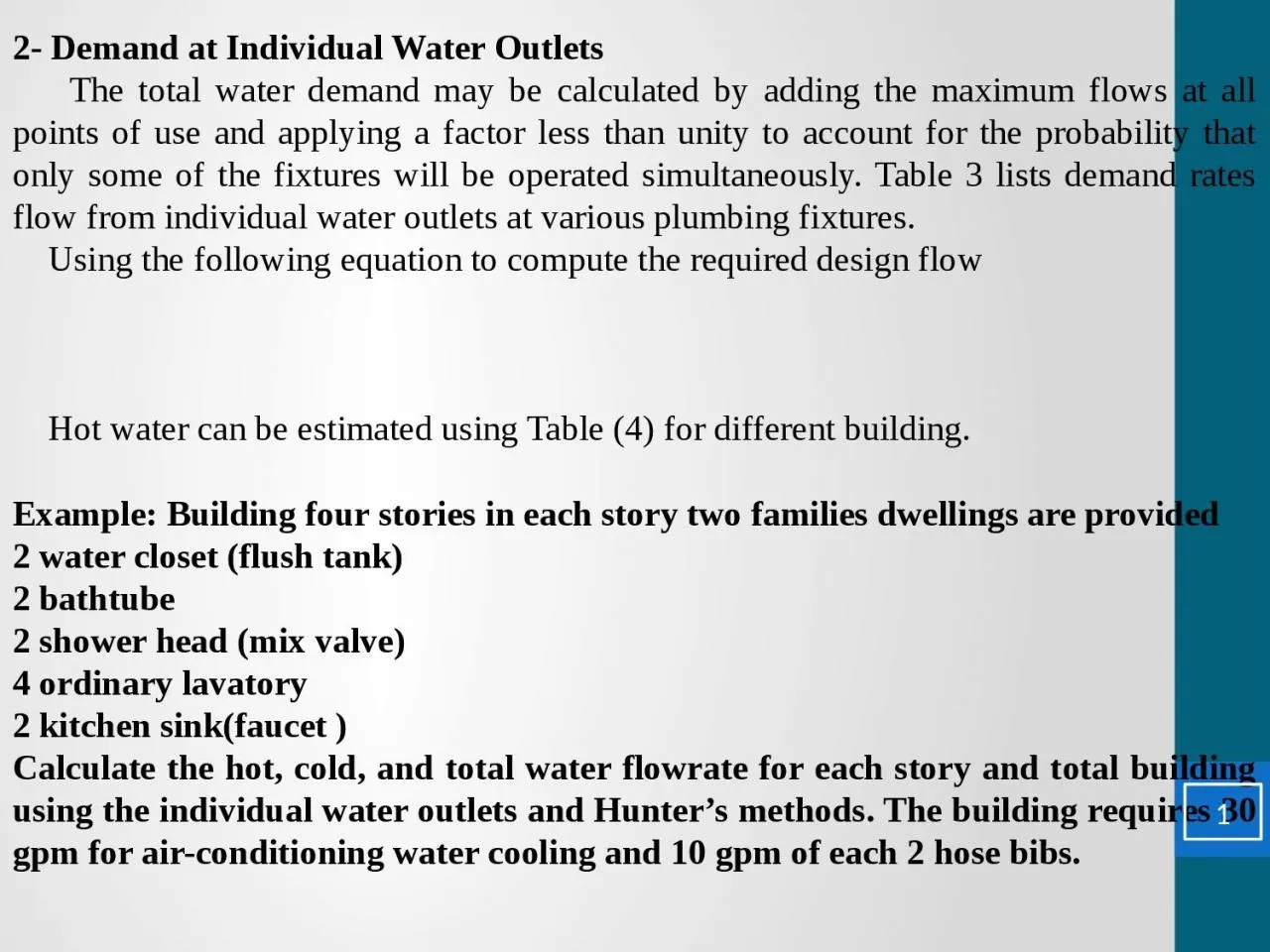
1. 2- Demand at Individual Water Outlets The total water demand may be calculated by adding the maximum flows at all points of use and applying a factor less than unity to account for the probability that only some of the fixtures will be operated simultaneously. Table 3 lists demand rates flow from individual water outlets at various plumbing fixtures. Using the following equation to compute the required design flow Hot water can be estimated using Table (4) for different building.Example: Building four stories in each story two families dwellings are provided 2 water closet (flush tank)2 bathtube2 shower head (mix valve)4 ordinary lavatory 2 kitchen sink(faucet )Calculate the hot, cold, and total water flowrate for each story and total building using the individual water outlets and Hunter’s methods. The building requires 30 gpm for air-conditioning water cooling and 10 gpm of each 2 hose bibs. 1
2. Fixture typeQuantityDemand gpmCold waterHot waterw.c 236-bathtube2510-bathtube20.333-0.667shower2510-shower20.5-1Lavatory428-Kitchen sink2612-Kitchen sink20.17-0.333Total462Solution: Individual Water Outlets Cold Water 2
3. Continuous water demand = 30 + 10 2 = 50 gpm for each story for total building Hot Water2 - Hinter’s method 3
4. Fixture typeQuantityF.UHot waterCold waterTotalw.c 25-1010bathtube2366-bathtube24--8shower2366-shower24--8lavatory41.566-lavatory42--8Kitchen sink2366-Kitchen sink24--8Total of each story243442Hot Water For each story 24 f/u=15 gpm for total building 96 f/u= 43 gpm Cold Water for each story 34 f/u= 23 gpm for total building 136 f/u = 52 gpm Total flow for each story 42 f/u = 48 gpm for total building 168 f/u = 86 gpm4
5. Continuous demand 30 + 2 = 50 gpmHot water = 15 gpm for each story = 43 gpm for total buildingCold water 23+50 = 73 gpm for each story 52 + 50 = 102 gpm for total buildingTotal flow 48 + 50 = 98 gpm for each story 86 + 50 =136 gpm for total buildingExample:Determine heater and storage tank size for an apartment building from a following number of fixtures. QuantityFlow per fixture gal/hrHot water demand gal/hrLavatories (private)212030 bathtubs2060030 showers3090060 kitchen sink1060015 lundry tubs2030025205
6. Probable maximum demand = 0.3 2520 = 756 gphStorage tank capacity = 1.25 756 = 945 gal Static head It is the measure of elevation of water above a reference point.Dynamic head It is static head minus the friction loss of a flowing liquid, expressed as shown in Fig. Friction head lossDynamic headStatic headThe water distribution system must be always be designed on basis of the minimum pressure available. Generally, the minimum pressure to be provided at most fixture is 8 psi (55 kpa) and 6
7. from 15 to 25 psi for water closet. Friction head loss Water piping must be sized to limit the friction head losses in the piping system so that the highest and most remote water outlet will have the required minimum pressure head for adequate flow during periods of peak demand. The maximum friction head loss that can therefore be tolerated in the system during peak demand is the difference between the static pressure at the highest and most remote outlet at no flow conditions and the minimum flow pressure required at that outlet. For brass, copper, or plastic pipingFor galvanized-steel and wrought-iron piping 7
8. Using Hizen-Williamz Eq. For greater accuracy , it was suggested that water supply pipe be considered in four classes as to hydraulic roughness: 8
9. Example There is 4-story building where the street pressure is reported as 22 m. Design the pipes of water supply network shown in Fig. if the pipes are galvanized-steel piping. F AEDCB14 m14 m14 m14 m 25 m3m3.5 m3.5 m3.5 m240 l/min240 l/min240 l/min240 l/minTo find slope of hydraulic pressure of branches Point C : 9
10. Point D: PointLSC12.354210.588D8.725210.415E5.095210.243F1.466210.07PointLSC12.354210.588D8.725210.415E5.095210.243F1.466210.07PipeSlopeTotal Discharge l/minDesign Discharge, l/minCal. Diameter, mmSel. Diameter, mmABC0.03796024868.770CD0.03772021564.970DE0.03748017559.860EF0.03724012452.155CC’0.58824012429.930DD’0.41524012432.135EE’0.24324012435.740FF’0.0724012445.85010
11. Example:Design pipes of water supply network shown in Fig. Using Hizen-Williamz Eq. for steel Pipes , C=100 HGFEDCBA 240 l/min 240 l/min 240 l/min 240 l/min 240 l/min 240 l/min 14 m14 m 14 m14 m14 m14 m3.5 m3.5 m3.5 m3.5 m3.5 m7.5 m20 mStorage tank11
12. Solution: Calculation of friction loss and slope of pressure hydraulicLine ABCC’ LineLSABCC’1.8962.250.03ABDD’5.3967.50.08ABEE’8.8972.750.122ABFF’12.3978.00.159ABGG’15.8983.250.191ABHH’19.3988.50.219LineLSABCC’1.8962.250.03ABDD’5.3967.50.08ABEE’8.8972.750.122ABFF’12.3978.00.159ABGG’15.8983.250.191ABHH’19.3988.50.219Minimum S = 0.03Calculation at points and slopes of pressure Point C: 12
13. PointsLSC1.065210.051D4.46210.212E7.855210.374F11.25210.536G14.645210.697H18.04210.859PointsLSC1.065210.051D4.46210.212E7.855210.374F11.25210.536G14.645210.697H18.04210.859Pipes SDia. Cal. , mmDia. sel. , mmABC0.031440303.67880CD0.031200277.175.280DE0.03960247.972.175EF0.03720214.768.270FG0.03480175.363.265GH0.03240123.955.360CC’0.051240123.949.650DD’0.212240123.937.140Pipes SDia. Cal. , mmDia. sel. , mmABC0.031440303.67880CD0.031200277.175.280DE0.03960247.972.175EF0.03720214.768.270FG0.03480175.363.265GH0.03240123.955.360CC’0.051240123.949.650DD’0.212240123.937.14013
14. Pipes SDia. Cal. , mmDia. Sel. , mmEE’0.374240123.933.035FF’0.536240123.930.635GG’0.697240123.929.0330HH’0.859240123.927.830Pipes SDia. Cal. , mmDia. Sel. , mmEE’0.374240123.933.035FF’0.536240123.930.635GG’0.697240123.929.0330HH’0.859240123.927.83014
15. Example: There are 3- story building where the street is reported as 32 psi. Design the pipes of water network shown in figure. If the pipes are galvanized-steel smooth pipe ABCEDE’C’D’300 l/min300 l/min300 l/min30 ft12 ft10 ft12 ft20 ft20 ft20 ftPressure or head lossThe pressure required must be adequate for all pipes. The minimum pressure is along path ABEE’ isPressure of points: 15
16. PointsPP/100C15.25276.26D8.7343.65E2.211PipesP/100Dia. Cal. mmDia. Sel. mmABC11.049002403940CD11.046001963640DE11.043001393235CC’76.263001392125DD’43.653001392425EE’113001393235PipesP/100Dia. Cal. mmDia. Sel. mmABC11.049002403940CD11.046001963640DE11.043001393235CC’76.263001392125DD’43.653001392425EE’113001393235Example : Design water lines shown in figure16
17. ABCEL=260 ftFU=60L=1500 ftRough pipe EL=263 ftFU=40L=1000 ftRough pipe EL=360 ftEL=353 ftEL=263 ft For F.U = 40 q = 47 gpm 17
18. For F.U= 60 q = 55 gpmDesign from tank to AUsing the minimum pressure from tank to C = 0.687 psi Example: There is a 16-story building where the street pressure is reported as 45 psi. The highest outlet is 180 ft above the level of the pumps and the pumps are at the same level as the street main. The building has flush valve water closets and the required pressure at the highest fixture is 20 psi. The total combined cold and hot water fixture count for the building is 4840 F.U. The length of run from the pumps to the farthest and highest fixture is 350 ft. Material for the water service into the building will be type copper piping. Calculate the pump capacity in psi and design the main pipe( head loss through pump is 5 psi). 18
19. Example : Design pipes of water supply network shown in Fig. using 19
20. FEDC 300 l/min 300 l/min 300 l/min 300 l/min 20 m20 m20 m20 m3.5 m3.5 m3.5 m8 mStorage tank 10 mAB20