

National Geodetic Survey Andria Bilich amp Gerald Mader Geosciences Research Division National Geodetic Survey With contributions from Steven Breidenbach Hong Chen Kendall Fancher ID: 180876
Download Presentation The PPT/PDF document "GNSS Absolute Antenna Calibration at the" is the property of its rightful owner. Permission is granted to download and print the materials on this web site for personal, non-commercial use only, and to display it on your personal computer provided you do not modify the materials and that you retain all copyright notices contained in the materials. By downloading content from our website, you accept the terms of this agreement.


Slide1
GNSS Absolute Antenna Calibration at theNational Geodetic Survey
Andria
Bilich
& Gerald
Mader
Geosciences Research Division
National Geodetic Survey
With contributions from
:
Steven
Breidenbach
, Hong Chen,
Kendall
Fancher
, Charles
Geoghegan
,
David
Gietka
,
Heeyul
Han, Dennis
Lokken
,
Frank Marion, Jaya
Neti
,
Jarir
SalehSlide2
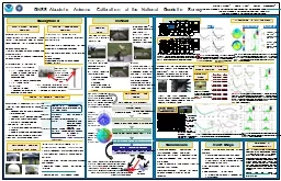
OutlineMotivation
NGS methods and observation models
Example results
NGS Calibration Services
9/23/2010
ION GNSS 2010
2Slide3
Where do I receive the signal?
Antenna reference point (ARP)
Antenna element
Nonphysical and inconstant point floating in space?
9/23/2010
3
ION GNSS 2010Slide4
What is GNSS Antenna Calibration?
Create a “map” of antenna characteristics
Mean point being positioned (
PC0
)
Spatial variations (PCV)
9/23/2010
ION GNSS 2010
4
PC0
[ENU]
PCV
(el)
PCV
(
az,el
)Slide5
What Is The Effect of PC0/PCV?
Antenna element introduces elevation- (and azimuth-) dependent advance/delay to the carrier phase observation = PC0 + PCV
Effect on heights (with respect to elevation cutoff)
Alias into troposphere estimate
<= 10cm height errors on mixed-antenna baselines
Mixed-antenna and longer baselines demand good antenna calibrations
Published values are idealized (environment-free)
9/23/2010
5
ION GNSS 2010Slide6
NGS Motivations and Goals
Serve high precision needs of U.S. surveying and geodesy communities
Simultaneous multi-freq, multi-GNSS calibrations
2-D (elevation, azimuth) phase center patterns
Free calibration service w/ quick turn-aroundCalibration values publicly distributed via InternetCompatibility with IGS ANTEX values
9/23/2010
ION GNSS 2010
6Slide7
NGS Calibration Facility and Methods
9/23/2010
ION GNSS 2010
7Slide8
Calibration Setup
Single differences
Short baseline (5 m)
Simplified multipath environment
Common clock (heading receiver)Remaining factors = phase centers (ref, test), differential multipath, hardware bias
9/23/2010
8
ION GNSS 2010Slide9
Time Difference of Single Differences
Closely spaced time pairs + robot motion =
PC0/PCV at reference antenna removed
slowly varying biases (differential MP, hardware bias) minimized
9/23/2010
9
ION GNSS 2010
Fixed reference antenna
Test antennaSlide10
Why Robot?
Introduce angle changes for TDSD
Better spatial coverage
9/23/2010
10
ION GNSS 2010Slide11
Modelled Factors
E
N
V
PC0 [ENU]
PCV (
az,el
)
A priori
position
Frame rotation(s) between robot and local frame
Rotation arm length
Phase windup (antenna motion)
9/23/2010
11
ION GNSS 2010Slide12
NGS Calibration Results
9/23/2010
ION GNSS 2010
12
mmSlide13
Trimble Zephyr Geodetic 2(TRM55971.00)
9/23/2010
ION GNSS 2010
13
(mm)
North
East
Up
IGS
1.07
-0.19
67.17
30212661
1.38
-0.45
69.84
30212716
0.92-0.47
69.84Slide14
TRM55971.00phase center pattern
9/23/2010
ION GNSS 2010
14
mm
mmSlide15
Deviation from IGS type mean
9/23/2010
ION GNSS 2010
15
mmSlide16
Ashtech
Geodetic III ‘Whopper’
(ASH700718B)
9/23/2010
ION GNSS 2010
16
(mm)
North
East
Up
IGS
-1.67
-0.47
69.48
11885
-1.22
0.22
69.1311869-1.40
0.2369.17Slide17
ASH700718Bphase center pattern
9/23/2010
ION GNSS 2010
17
mm
mmSlide18
Deviation from IGS type mean
9/23/2010
ION GNSS 2010
18
mm
mm
mmSlide19
NGS Calibration Services
9/23/2010
ION GNSS 2010
19Slide20
PC0/PCV Distribution
Freely available
Distribution via website:
http://www.ngs.noaa.gov/ANTCAL
Data formats for different software:
NGS format (relative and absolute)ANTEX (absolute)
9/23/2010
ION GNSS 2010
20Slide21
NGS Calibration ServicesFormal policy document
Calibration process and stages
Eligibility for calibration
Rights and responsibilities
Request calibration via web formTracking system with automated customer notification emails
9/23/2010
ION GNSS 2010
21Slide22
Conclusions and OutlookGood agreement with IGS type means
Pending approval from International GNSS Service (IGS)
Soon to be “open for business”
For more information
http://www.ngs.noaa.gov/ANTCALEmail
andria.bilich@noaa.gov or NGS.AbsAntCal@noaa.gov
9/23/2010
ION GNSS 2010
22