
tial Information Sciences Vol XXXVIII Part 5 Commission V Symposium Newcastle upon Tyne UK 2010 484 CAMERA CALIBRATION T ECHNIQUES USING MULT IPLE CAMERAS OF DIFFERENT RESOLUTION S AND BUNDLE ID: 222441
Download Pdf The PPT/PDF document "International Archives of Photogrammetry..." is the property of its rightful owner. Permission is granted to download and print the materials on this web site for personal, non-commercial use only, and to display it on your personal computer provided you do not modify the materials and that you retain all copyright notices contained in the materials. By downloading content from our website, you accept the terms of this agreement.


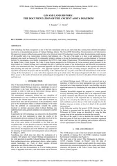
International Archives of Photogrammetry, Remote Sensing and Spa tial Information Sciences , Vol. XXXVIII, Part 5 Commission V Symposium, Newcastle upon Tyne, UK. 2010 484 CAMERA CALIBRATION T ECHNIQUES USING MULT IPLE CAMERAS OF DIFFERENT RESOLUTION S AND BUNDLE OF DIST ANCES K . Nakano a, b and H . Chikatsu c a System Development Group, AERO ASAHI CORPORATION kazuya - nakano@aeroasahi.co.jp b Architecture, Civil and Building En Tokyo Denki University c Department of Civil and Environmental Engineering, Tokyo Denki University chikatsu@g.dendai.ac.jp Commission V, WG V/ 1 KEY WORDS: Multiple cameras , D if ferent resolutions, Laser distance meter , Bundle adjustment , Camera - variant parameters ABSTRACT: A c onvenient 3D measurement using a consumer grade digital camera is enormously expected in various fields with the appearance of low cost and high resoluti developing a convenient 3D measurement system which is called as IBIM ( Image Based Integrated Measurement ) system. The device of IBIM system consists of a con sumer grade digital camera and laser distance meter. The most remarkable point of the system was its ability to calculate exterior orientation parameters and interior orientation parameters and the pseudo GCPs (Ground Control Points) without using a scale bar or the GCPs in object field. H owever, there were still some issues which need to be resolved before this system may become operational. These problems include, improvement of labor and time consuming in distance measurement and the deterioration of ima In order to resolve these problems , the IBIM system is improved using triplet images of multiple cameras of different resolutions and bundle of distances. This paper describes camera calibration techniques and its evaluations using images of mu ltiple cameras of different resolutions and bundle of distances. 1. INTRODUCTION Convenient 3D measurement using consumer grade digital camera is enormously expected in various fields with the appearance of low cost and high resolution consumer grade digit al cameras. In these circumstances, c alibration methods to perform convenient 3D measurement using consumer grade digital cameras were proposed (Chikatsu & Kunii, 2002; Habib & Morgan, 2003) and software for digital photogrammetry was also designed (C hikatsu & Kunii, 2002; Chikatsu & Ohdake, 2006; Fraser & Hanley, 2004; Fraser et al., 2008). However, these almost software requires GCPs which have exact 3D coordinates for camera calibration or scale bar for absolute orientation or interior orientation p arameters which should be acquired beforehand. These restrictions should be removed for an ideal convenient photogrammetry using consumer grade digital cameras. With this objective, the authors have been concentrating on developing a convenient 3D measurem ent system. One of photogrammetric systems is Image Based Integrated Measurement system called as IBIM system. The device of laser distance meter (Ohdake & Chikatsu, 2007). The most notable point of the system was its ability to calculate exterior orientation parameters and interior orientation parameters and pseudo GCPs without scale bar or GCPs in object field. There were still issues, however, as further work. These issues are improvement of lab or and time consuming in distance measurement and the deterioration of image quality. Identification for the same points and the detection of occlusion area in measuring procedures at different camera positions are performed with labor and time consuming a s manual task. In particular, the deterioration of image quality is caused by a half mirror, and the images in IBIM system are taken through the half . Therefore, the deterioration of image quality was unavoidable problem. In order to resolve these p roblems , IBIM system is improved using triplet images of multiple cameras of different resolutions and bundle of distances. This paper describes camera calibration techniques and its evaluations using images of multiple cameras of different resolutions and bundle of distances. 2. IBIM SYSTEM 2.1 The device of IBIM System The device of IBIM system consists of a consumer grade digital camera (OLYMPUS C - 770 Ultra Zoom, 4.0 mega pixels), a laser distance meter (Leica DISTO Lite 4 and full/half - mir rors, and it is able to rotate in vertically and horizontally so that precise distance from the centre of digital camera to feature point s on object field can be measured. Furthermore, the camera and laser axis can be precisely adjusted using 4 adjusting screw on the eaves. Figure 1 shows the appearance of the device of IBIM system , and Figure 2 shows the configuration s of the device of IBIM system. Table 1 shows configurations of laser distance meter from user manuals ( Leica, 2009). International Archives of Photogrammetry, Remote Sensing and Spa tial Information Sciences , Vol. XXXVIII, Part 5 Commission V Symposium, Newcastle upon Tyne, UK. 2010 485 Figure 1. Appearan ce of IBIM system Figure 2. Configuration of the system Model Leica DISTO lite 4 Measuring accuracy ±3mm Smallest unit 1mm Range 0.3 m to 100m Laserspot (at distance) 6/30/60mm (10/50/100m) Laser Visible ; 635nm Dimensions 154×69×44mm Weight 360g Table 1. Specification of l aser distance meter 2.2 IBIM System Ohdake and Chikatsu (2007) develop ed IBIM system which have ability to calculate both of exterior orientation parameters and interior orientation parameters without scale distance or GCPs in obj ect field using stereo images . Figure 3 shows t he concept of IBIM system using 2 IBIM dataset which consist of stereo images and distances from the d ifferent exposure stations. However, there were still some issues. One issue is deterioration of image qual ity which is caused by the half mirror of the device of IBIM system . This problem is very important problem for the practical IBIM system to perform image based stereo matching and 3D texture model. Other issue is labor and time consuming in distance measu rement . In order to remove these issues , IBIM system is redefine d as camera calibration system using triplet images and bundle of distances i n this paper . The both side images of the IBIM device are taken using the other digital cameras. Figure 4 shows the concept of IBIM system using triplet images. Table 2 shows the specifications of digital camera s . Figure 3 . IBIM system using Stereo images Figure 4 . IBIM system using Triplet images Supplier Camera model Pixel [M] Lens [mm] Sensor type / size O LYMPUS C - 770Ultra Zoom 4.0 6.3 1/2.5 â SONY Cyber - shot DSC - N1 8.1 7.9 1/1.8â Nikon COOLPIX S600 10.0 5.0 1/2.33 â PENTAX Optio W60 10.0 5.0 1/2.3â Panasonic DMC - FX100 12.0 6.0 1/1.72â Nikon COOLPIX S710 14.5 6.0 1/1.72â Canon EOS 20D 8.2 17.0 22. 5×15.0 [mm] Canon EOS Kiss X3 15.1 17.0 22.3×14.9 [mm] Table 2. Specifications of digital cameras 2.3 Coordinate s System T he c oordinate s system of the IBIM system is local coordinates system which takes into account an absolute orientation. Figure Mirror Half mirror Camera axis Laser axis Y axis Digital camera Laser Distance Meter X axis International Archives of Photogrammetry, Remote Sensing and Spa tial Information Sciences , Vol. XXXVIII, Part 5 Commission V Symposium, Newcastle upon Tyne, UK. 2010 486 5 shows the coordinate s system of the IBIM system which i s defined as follows: i) The origin is O c , which is the centre of digital camera on the IBIM device . ii) 3D coordinate of p seudo GCPs are computed using image coordinate s and distances which are obtained by the l aser distance meter. iii) 3D coordinate of the pseudo GCPs are t ransform ed into local coordinate system, which P 1 is origin p oint. iv) X axis direction is given using the other pseudo GCP ( P 2 ) . v) Z value for the pseudo GCP ( P 3 ) is given as 0 . Figure 5. Coordinat e s system of the IBIM system 2.4 Initial value The i nitial value of the pseudo GCPs are computed using relationship with bundle of distances, focal length and image coordinates of the IBIM device . Horizontal angle ( α ) and vertical angle ( β ) are computed by the image coordinate s and nominal focal length using E quation (1) (Wolf, 1974). 3D coordinates of the pseudo GCP P in figure 6 is obtained using the angles and the distance from the centre of digital camera ( O c ) in the IBIM device from E quation (2) . Figure 6 shows the geometric condition of pseudo GCP. Figure 6. Angles of pseudo GCP on the image (1) w here, α, β = angles from X, Y axis ( 2 ) w here, X, Y, Z = i nitial value of pseudo GCP on ground coordinate s On the other hand, e ach approximate exterior orientation parameter of triplet images is calculated by single orientation using the pseudo GCPs and the nominal value of the interior orientation parameters. 2.5 Camera Calibration In order to use the multiple cameras of different resolutions, unknown parameters are exterior parameters ( X 0 , Y 0 , Z 0 , Ï , Ï , κ ) and the interior parameters { f (focal length), u 0 , v 0 (principal points), a , b (scale factor, shear factor), k 1 , k 2 (lens distortion)} for triplet images respectively and pseudo GCPs ( X i , Y i , Z i ). These unknown parameters are calculated by colline arity condition and constraint of bundle of distances simultaneously under the local coordinate system. Here, coll inearity condition is shown as E quation ( 3 ), and distance condition is shown as E quation ( 4 ). T hese unknown parameters can be calculated as th e values by minimizing following function H (Equation (5)) under the least square method. ( 3 ) where, x, y = image coordinate s f = focal length X , Y , Z = object coordinate s of pseudo GCP X 0 , Y 0 , Z 0 = perspective centre m ij = element s of rotation matrix ( 4 ) where, D = distance from feature point to perspective centre X, Y, Z = object coordinate s of pseudo GCP X 0 , Y 0 , Z 0 = perspective centre of centre position (5) where, Î x ij , Î y ij = residuals for image coordinate s Î D j = residuals for distance M = number s of pseudo GCP N = number s of image p 1 i = weight for image coordinates p 2 = weight for distance Furthermore, the radial polynomial 5th degree of E quation (6) was adapted to correct lens di stortion in this paper (Fryer J. G. and Brown D.C, 1986). Y X y x O c P 1 (0 , 0 , 0 ) P 2 ( X, 0 , 0 ) P 3 ( X,Y, 0 ) Z y x p ( x,y ) α β f P ( X,Y,Z ) O c ï¨ ï© ï¨ ï© ãã 2 2 1 1 tan tan f x y f x ï« ï½ ï½ ï ï ï¢ ï¡ ï¢ ï¡ ï¢ ï¢ ï¡ cos cos sin cos sin D Z D Y D X ï½ ï½ ï½ ï¨ ï© ï¨ ï© ï¨ ï© ï¨ ï© ï¨ ï© ï¨ ï© ï¨ ï© ï¨ ï© ï¨ ï© ï¨ ï© ï¨ ï© ï¨ ï© 0 33 0 32 0 31 0 23 0 22 0 21 0 33 0 32 0 31 0 13 0 12 0 11 Z Z m Y Y m X X m Z Z m Y Y m X X m f y Z Z m Y Y m X X m Z Z m Y Y m X X m f x ï ï« ï ï« ï ï ï« ï ï« ï ï ï½ ï ï« ï ï« ï ï ï« ï ï« ï ï ï½ ï¨ ï© ï¨ ï© ï¨ ï© 2 0 2 0 2 0 C C C Z Z Y Y X X D ï ï« ï ï« ï ï½ ï¨ ï© ï¨ ï© ï» ï½ min 1 1 2 2 2 2 1 ï ï ï« ï ï« ï ï½ ï¥ ï¥ ï½ ï½ m i n j j ij ij i D p y x p H International Archives of Photogrammetry, Remote Sensing and Spa tial Information Sciences , Vol. XXXVIII, Part 5 Commission V Symposium, Newcastle upon Tyne, UK. 2010 487 (6) Where, x, y = corrected image coordinates x', y' = image coordinates K 1 , K 2 = coefficients of radial distortion r = radial distance from principal points Due to diffe r ent measurement accuracy of the digital cameras and laser distance meter , it must be determine d weight s ( p 1 i , p 2 ) for camera calibration using Equation (7). I t can be presumed that pointing accuracy of image coordinates is determination accuracy for laser spot of the laser distance meter on the image. Therefore, it i s estimated that pointing accuracy is 1.5 pixels by followings , the diameter of laserspot spreads depending on measurement distance from T able 1 and d ivergence of laser beam which is computed by distance and diameter is 0.6 mrad . O n the other hand, measur ement accuracy of the laser distance meter is 3mm at twice the standard deviation from user manual . I t is supposed that the real measurement accuracy is higher than the specification value . S tan dard deviation of the laser distance meter is 0.5mm , which was obtained by indoor experiment . F or example, weights for the DSC - N1 (8 M ) , the IBIM device (C - 770UltraZoom: 4M), the COOLPIX S600 (10 M ) and distance, p 11 , p 12 , p 13 and p 2 are defined as 5: 2: 6: 3. ( 7 ) where, p 1 i = weight for image coordinates p 2 = weight for distance Ï Gi = measurement accuracy in object field Ï D = standard deviation of distance 3. EXPERIMENT 3.1 Detail of experiment Indoor experiment was performed using 6 consumer grade digital cameras (4M,8M,10Mx2,12M,14.5M) and 2 single lens reflex digital cameras (8M, 1 5.1M). Figure 7. Test target A test target (H: 640mm, W: 480mm, D: 20mm) with 165 black circular points and 14 red circular points was used in this paper. The red circle points inside of thin line square are control points for camera calibration and 1 43 black circle points outside of thick line rectangle are check points. E ach black circular point was manufactured with ± 0.05mm accuracy, and pixel coordinates for these points were obtained as area gravity by image processing procedures. 5 triplet images for every camera were taken with changing altitude between 0.65 - 0.96m so that uniform image scales be able to keep, and camera calibrations were performed by the simultaneous adjustment using pseudo GCPs and bundle of distances. 3.2 Camera - v ariant p arameters set There are some combinations of digital cameras in consideration of using multiple cameras. For example, A is digital camera of the IBIM device . B and C are other digital cameras. It is possible to create the combinations of digital cameras such as typ e 1 (A , A , A), type 2 (B , A , B) and type 3 (B , A , C or C , A , B). These combinations are led to camera calibration with block - invariant (Fraser, 1987) , photo - variant (Shortis, et al., 1998) , image - variant (Techkenburg, et al, 2001) and camera - variant parame ter sets. Camera - variant parameter set is defined as calibration parameters for each camera are unknown values in this paper . In other words, unknown parameters of camera - variant parameter set are principal point ( u 0 , v 0 ), focal length ( f ), scale factor ( a , b ) and coefficient of lens distortion ( K 1 , K 2 ) for each image respectively. I n order to evaluate the efficiency of camera - variant parameters set, camera calibration for 8 cameras w ere performed using type 1 or type 2. In this section , index of accuracy m eans the s um of mean error ( Ï L ) which is computed from Equation (8) using root mean square error for 143 points for 8 cameras respectively. (8) w here, Ï L = sum of the mean error i = camera model m = numbers of cameras Ï l = mean error Ï X , Ï Y , Ï Z = roo t mean square error Figure 8 shows relationship between accuracy and numbers of pseudo GCP for each calibration model respectively. Note that t he number s such as C09 means numbers of pseudo GCP. From Figure 8, i t cannot find significant differences betwe en block - invariant , photo - variant and image - variant parameter set . O n the other hand, c amera - variant parameter set are small in comparison with other parameter set with 40%. It can be found that accuracy of 15 and 17 pseudo GCPs are lower than 13 pseudo G CPs, i t is inferred that accuracy wa s influenced by increasing of pseudo GCPs which are locate at border . The results of 9 pseudo GCPs show large st sum of ellipsoid error in each parameter set. T herefore, i t is estimated that the IBIM system need s more th an 11 pseudo GCPs from the point of view of degree s of freedom . C onsequently , i t can be said that camera - variant parameter set shows the most stable result. ï¨ ï© ï¨ ï© 2 2 5 2 3 1 5 2 3 1 y x r r K r K r y y y r K r K r x x x ï¢ ï« ï¢ ï½ ï« ï¢ ï« ï¢ ï½ ï« ï¢ ï« ï¢ ï½ ã ã ï³ ï³ ï³ ï³ 2 2 3 2 2 2 1 2 13 12 11 1 : 1 : 1 : 1 : : : D G G G p p p p ï½ 2 2 2 1 Z Y X l m i l L ï³ ï³ ï³ ï³ ï³ ï³ ï« ï« ï½ ï½ ï¥ ï½ International Archives of Photogrammetry, Remote Sensing and Spa tial Information Sciences , Vol. XXXVIII, Part 5 Commission V Symposium, Newcastle upon Tyne, UK. 2010 488 Figure 8. Influence of interior parameter set 4. EVALUATIONS T he e valuation of the IBIM system using camera - variant parameters was performed using 6 combinations with 8 digital cameras. Table 3 shows combinations of digital cameras. Camera Combinations name Resolutions Left Right Cyber - shot DSC - N1 COOLPIX S600 N1 - S600 8.1M - 4.0M - 10.0M COOLPIX S 600 Optio W60 S600 - W60 10.0M - 4.0M - 10.0M Optio W60 DMC - FX100 W60 - FX100 10.0M - 4.0M - 12.0M DMC - FX100 COOLPIX S710 FX100 - S710 12.0M - 4.0M - 14.5M COOLPIX S710 EOS 20D S710 - 20D 14.5M - 4.0M - 8.2M EOS 20D EOS Kiss X3 20D - X3 8.2M - 4.0M - 15.1M Table 3 . Combinations o f digital cameras 4.1 Accuracy In order to evaluate accuracy, normalized accuracy for 143 check points were drawn in Figure 7 . It should be noted that normalized accuracy means the ratio of RMS error in each type to standard error. N ormalized accuracy is calc ulated by Equation (9). Therefore , the ratio larger than 1 means higher accuracy than standard error which is computed from Equation ( 10 ) ( Abdel - aziz, 1982 ) , and it is estimated that exceeded accuracy rather than standard error is inferred that pointing of image coordinates were performed more than 1 pixel. (9) w here, Ï X , Ï Y , Ï Z = RSM error of X, Y, Z Ï Xi , Ï Yi , Ï Zi = differences in X, Y, Z coordinates n X , n Y , n Z = numbers of check points Ï X 0 , Ï Y 0 , Ï Z 0 = standard error ( 10 ) w here, Ï X 0 , Ï Y 0 , Ï Z 0 = standard error H = altitude f = focal length B = base line Ï P = pointing accuracy Figure 9. Normalized accuracy The followings are found from Figure 9 . i) The IBIM system using multiple cameras of differ ent resolutions has ability to obtain the equivalent accuracy with standard error. ii) The numbers of pseudo GCPs does not have significantly influence on accuracy. iii) The IBIM system has ability to obtain the stable result without resolution of the digital camer a s. 4.2 Precision In general, precision is standard deviation which is computed by equation using weighted coefficient matrix derived by variance - covariance information, and precision is evaluated by an equation using the sum of deviation for each check poin t in this paper (Beyer, 1992). Figure 10 shows normalized precision which is computed using standard error in the same procedure as accuracy. Precision shows the same tendency as accuracy, and the value of precision shows high value in comparison with accu racy. (11) w here, = standard deviation for check points = standard deviation of unit weight = diagonal element of the inverse of the normal equation matrix at the position of the corresponding unknown n X , n Y , n Z = numbers of check points 0 5 10 15 20 25 30 35 40 45 50 Block - invariant Photo - invariant Image - variant Camera - Variant Sum of diameter of spherial error C09 C11 C13 C15 C17 [mm] Z Zi Z Y Yi Y X Xi X Z Y X Z Y X n n n ï¥ ï¥ ï¥ ï½ ï½ ï½ ï« ï« ï« ï« 2 2 2 2 0 2 0 2 0 2 2 2 , , 1 ï³ ï³ ï³ ï³ ï³ ï³ ï³ ï³ ï³ ï³ ï³ ï³ ã ã ã ã p Z p Y X B H f H f H ï³ ï³ ï³ ï³ ï³ 2 0 0 0 ï½ ï½ ï½ ã 0.0 0.2 0.4 0.6 0.8 1.0 1.2 1.4 1.6 1.8 N1 | S600 S600 | W60 W60 | FX100 FX100 | S710 S710 | 20D 20D | X3 Normalized accuracy C11 C13 C15 C17 Z Zi Z Y Yi Y X Xi X Z Z Zi Y Y Yi X X Xi n n n q q q i i i i i i ï¥ ï¥ ï¥ ï½ ï½ ï½ ï½ ï½ ï½ 2 2 2 0 0 0 Ë Ë , Ë Ë , Ë Ë Ë Ë , Ë Ë , Ë Ë ï³ ï³ ï³ ï³ ï³ ï³ ï³ ï³ ï³ ï³ ï³ ï³ ã ã ã ã ã ã Zi Yi Xi ï³ ï³ ï³ Ë , Ë , Ë 0 Ë ï³ i i i i i i Z Z Y Y X X q q q , , International Archives of Photogrammetry, Remote Sensing and Spa tial Information Sciences , Vol. XXXVIII, Part 5 Commission V Symposium, Newcastle upon Tyne, UK. 2010 489 Figure 10. Normalized precision 5. CONCLUSIONS The IBIM ( Image Based Integrated Measurement ) System using multiple digital cameras of different resolutions was develop ed by the authors for a convenient digital photogrammetry, and camera calibration techniques and performance evaluation for the IBIM system were investigated in this paper. Though, the deterioration of image quality was unavoidable problem for the IBIM de vice since the deterioration of image quality is caused by half - mirror. It is verified, however, the deterioration of image quality is resolved by using the left and right side camera . In particular, it can be said that the camera - variant parameters have p ract ic ability in combination of the multiple cameras . Similarly, it is verified that it can't find significant differences between the accuracy of the IBIM system and standard error. Consequently, it is concluded that a convenient 3D measurement is accompl ished by the IBIM system which have ability to combine multiple cameras of different resolutions , and the IBIM system is expected to become a useful measurement system for the various close range application fields from view point of non - contact measuremen t. References : Abdel - Aziz, Y.I., 1982. Accuracy of the Normal Case of Close - Range Photogrammetry, Photogrammetric Engineering and Remote Sensing, 48(2), pp. 207 - 213. Beyer, H. A., 1992. Accurate Calibration of CCD - cameras, Proceedings of IEEE Computer Society Conference on Computer Vision and Pattern Recognition, pp. 96 - 101. Chikatsu, H., Kunii, Y., 2002. Performance Evaluation of Recent High Resolution Amateur Cameras and Application to Modeling of Historical Structure, International Archive s of Photogrammetry and Remote Sensing, Vol.XXXIV, Part5, pp. 337 - 341. C hikatsu, H., Ohdake, T., 2006. Ubiquitous Digital Photogrammetry by Consumer Grade Digital Camera, International Archives of the Photogrammetry, Remote Sensing and Spatial Information Sciences, Vol. XXXVI, PART 5 (CD - ROM), ISSN 1682 - 1750 Fraser, C.S., 1987, Multiple exposures in non - metric camera applications, Photogrammetria, 42, pp. 62 - 72. Fraser, C.S., Cronk, S., Hanley, H., 2008. Close - Range Photogrammetry in Traffic Incident Manag ement. International Archives of Photogrammetry, Remote Sensing and Spatial Information Sciences, Vol.XXXVII, PartB5, pp. 125 - 128. Fraser, C.S., Hanley, H.B., 2004. Developments in Close - Range Photogrammetry for 3D Modelling: The Iwitness Example, Interna tional Archives of Photogrammetry, Remote Sensing and Spatial Information Sciences, Vol. XXXVI - 5/W1, ISSN 1682 - 1777 Fryer, J. G. and Brown, D.C., 1986, Lens Distortion for Close - Range Photogrammetry, Photogrammetric Engineering and Remote Sensing, 52(1), p p. 51 - 58. Habib, A.F., Morgan, M.F., 2003. Automatic calibration of low - cost digital cameras, Optical Engineering, 42(4), pp. 948 - 955. Leica Geosystems, DISTO Classic4/Lite 4 User Manual Version1.0 English, pp.33 - 34, http://ptd.leica - geosystems.com/en/Supp ort - Downloads_6598.htm?cid=3965 (accessed 12 Dec. 2009) Ohdake, T., and Chikatsu H., 2007, Multi Image Fusion for Practical Image Based Integrated Measurement System, Optical 3 - D measurement Techniques VIII (1), pp. 56 - 63. Shortis, M.R., Robson, S., Beyer , H.A., 1998. Principal point behavior and calibration parameter models for Kodak DCS Cameras, Photogrammetric Record, 16(92), pp. 165 - 186. Tecklenburg, W., Luhmann, T., Hastedt, H., 2001. Camera Modelling with Image - variant Parameters and Finite Element s, Optical 3 - D Measurement Techniques V, pp. 328 - 335. Wolf, P. R., 1974. Elements of Photogrammetry, McGRAW - HILL INTERNATIONAL BOOK COMPANY, ISBN 0 - 07 - 085878 - 0, pp. 397 - 398. 0 2 4 6 8 10 12 N1 | S600 S600 | W60 W60 | FX100 FX100 | S710 S710 | 20D 20D | X3 Normalized precision C11 C13 C15 C17