
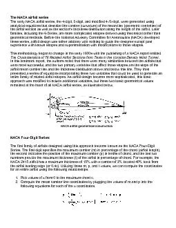
NACA airfoil geometrical constructionNACA FourDigit Seriesis approach became known as the NACA FourDigit NACA 2415 airfoil has a maximum thickness of 15the airfoil leading edge or 04c Utilizin ID: 844163
Download Pdf The PPT/PDF document "families including the 6Series are more ..." is the property of its rightful owner. Permission is granted to download and print the materials on this web site for personal, non-commercial use only, and to display it on your personal computer provided you do not modify the materials and that you retain all copyright notices contained in the materials. By downloading content from our website, you accept the terms of this agreement.


1 families, including the 6-Series, are mo
families, including the 6-Series, are more complicics (NACA) developed ion with modifications to those shapes. from Tests in the Varities between the airfoils that were most successful, and the two primary variables that affect those shapes are the slope of the remained at the heart of all NACA airfoil series, as illustrated below. NACA airfoil geometrical constructionNACA Four-Digit Series:is approach became known as the NACA Four-Digit NACA 2415 airfoil has a maximum thickness of 15%the airfoil leading edge (or 0.4c). Utilizing these m, p, and t values, we can compute the coordinates 1. Pick values of x from 0 2. Compute the mean camber li x = coordinates along the length of the airfoil,
2 fry = coordinates above and below the l
fry = coordinates above and below the line extending m = maximum camber in 3. Calculate the thickness distribution above (+) and below (-) the mean line by plugging the 4. Determine the final coordinates for the airfoil upper surface (x again indicate the maximum thickness (t) in percmaximum camber located calculate the coordinates1. Pick values of x from 0 2. Compute the mean camber line coordinates fo using the table shown below. 3. Calculate the thickness distribution using 4. Determine the final coordinates using the same equations as the Four-Digit Series. Modified NACA Four- and Five-Digit Series:names are slightly different as these shapes have beenthe NACA 0003.46-64.069, as an e
3 xample. The basic shape is thincreasingl
xample. The basic shape is thincreasingly more rounded nose. The second digit detedge. In this example, the locamum thickness and location thereof. Instead of being 3% thick, this airfoil is 3.46% thick. Instead of1. Pick values of x from 0 2. Compute the mean camber line coordinates using the same equations provided for the Four- 3. Calculate the thickness distribution above (+) and below (-) the mean line using these equations. The values of the a from the following table 4. Determine the "final" coordinates using the same equations 5. As noted above, this procedure yields a 20% th th. NACA 1-Series or 16-Series: Unlike those airfoil families discussed so far, the 1-Series was developed b
4 ased on airfoil theory 1930s, many advan
ased on airfoil theory 1930s, many advances had been made in inverse airfoil design methods. The basic concept behind result, these airfoils were not generexpressions like the Four- or Five-Digit Series. The 1-exemplified by the NACA 16-212. The first digit, 1, indicates the design lift coefficient in tenths (012%). Since the 16-XXX airfoils are the only ones that have ever seen behavior. The 6-Series was derived using an improvrelied on specifying the desired pressure distribution and employed advanced mathematics to especially since many different hat this family is designed for greater laminar location of the minimum pressure script 1 indicates that low drag is maintained at lift coefficient
5 s 0.1 airfoil chord over which the press
s 0.1 airfoil chord over which the pressure on the upper and lower surfaces. An example indicates the thickness distribution and mean line derived from earlier families are desi the fifth digit incidates the .3) and the final two integers are the an example being the NACA 835A216. The 8 designates Summary: Family Advantages Disadvantages Applications 1. Good stall characteristics 2. Small center of pressure movement 3. Roughness has little effect 1. Low maximum lift coefficient 2. Relatively high drag 1. General aviation Symmetrical: 1. Higher maximum lift coefficient 2. Low pitching moment 3. Roughness has little effect 1. Poor stall behavior 2. Relatively high drag 1. General aviation
6 2. Piston-powered bombers, 3. Commuters
2. Piston-powered bombers, 3. Commuters 1. Avoids low pressure peaks 2. Low drag at high speed 1. Relatively low lift 1. Aircraft propellers 2. Ship propellers 1. High maximum lift coefficient 2. Very low drag over a small range of 3. Optimized for high speed 1. High drag outside of the optimum range of operating 3. Poor stall behavior 4. Very susceptible to roughness 1. Piston-powered fighters 2. Business jets 1. Very low drag over a small range of 2. Low pitching moment 1. Reduced maximum lift 2. High drag outside of the optimum range of operating 3. Poor stall behavior 4. Very susceptible to roughness Unknown Unknown Very seldom used Today, airfoil design has in many ways returned t