
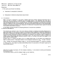
Introduction A new aspect in the design of beams will be considered in this chapter Previously we designed beams for strength In this part we will consider design of beams including the maximum deflection of the beam in the design specifications ID: 1022398
Download Presentation The PPT/PDF document "Chapter 9 Deflection of Beams" is the property of its rightful owner. Permission is granted to download and print the materials on this web site for personal, non-commercial use only, and to display it on your personal computer provided you do not modify the materials and that you retain all copyright notices contained in the materials. By downloading content from our website, you accept the terms of this agreement.


1. Chapter 9Deflection of Beams
2. IntroductionA new aspect in the design of beams will be considered in this chapter. Previously we designed beams for strength. In this part we will consider design of beams including the maximum deflection of the beam in the design specifications.The photo shows a cable-stayed bridge under construction. Its design is based on both strength considerations and deflection evaluations.2
3. Deformation Under Transverse LoadingRelationship between bending moment and curvature for pure bending.Example: Cantilever beam subjected to concentrated load at the free end.Curvature varies linearly with xAt the free end A, At the support B,3
4. Curvature is zero at points where the bending moment is zero, i.e., at each end and at E.Between A and E: M(x)>0 concave upwards Between E and D: M(x)<0 concave downwardsMax moment Max curvatureAn equation for the beam shape or elastic curve is required to determine maximum deflection and slope.Deformation Under Transverse LoadingExample: overhanging beam.4
5. Equation of the Elastic CurveThe curvature of a plane curve at a point Q(x,y) can be written asIn a beam is small andThe governing differential equation for the elastic curveis the flexural rigidity5
6. Equation of the Elastic CurveIntegrate the governing differential equation twice with respect to x The constants C1 and C2 are calculated from the boundary conditionsBeam deflectionBeam slope6
7. Equation of the Elastic CurveDetermination of C1 and C2Three cases for statically determinant beams,Simply supported beamOverhanging beamCantilever beam7
8. Example 189-1: For the loading shown, determine (a) the equation of the elastic curve for the cantilever beam AB, (b) the deflection at the free end, (c) the slope at the free end.
9. Example 19
10. Example 110
11. Example 2119-8: For the beam and loading shown, determine (a) the equation of the elastic curve for portion AB of the beam, (b) the slope at A, (c) the slope at B.
12. Example 212
13. Example 3139-15: For the beam and loading shown, knowing that a = 2 m, w = 50 kN/m, and E = 200 GPa, determine (a) the slope at support A, (b) the deflection at point C.
14. Example 314
15. Direct Determination of the Elastic CurveEquation for beam displacement becomesIntegrating four times yieldsFor a beam subjected to a distributed load,Constants C1, C2, C3 and C4 are determined from boundary conditions.15
16. Statically Indeterminate BeamsConditions for static equilibrium yieldIn a statically indeterminate beam, the deflection equations are used to solve for the reactions of the beamThe beam deflection equations,which introduces 2 unknowns but provides 3 additional equations from the boundary conditions:16
17. Example 4179-21: For the beam and loading shown, determine the reaction at the roller support
18. Example 418
19. Example 5199-26: Determine the reaction at the roller support and draw the bending moment diagram for the beam and loading shown.
20. Example 520
21. Example 6219-33: Determine the reaction at A and draw the bending moment for the beam and loading shown.
22. Example 622
23. Method of SuperpositionProcedure is facilitated by tables of solutions for common types of loadings and supports.For beams subjected to several concentrated or distributed loads: Compute separately the deformation of each of the applied loads The deformation of the combined load is found by adding the deformation of individual loads. 23
24. Example 7249-65: For the cantilever beam and loading shown, determine the slope and deflection at the free end.
25. Example 725
26. Example 726
27. Example 8279-80: For the uniform beam shown, determine (a) the reaction at A, (b) the reaction at B.
28. Example 828
29. Example 829
30. Example 9309-82: For the uniform beam shown, determine the reaction at each of the three supports.
31. Example 931
32. Example 932