

Engineering Elegant Systems Engineering at the System Level Consortium Team UAH George Washington University Iowa State Texas AampM Dependable System Technologies LLC Multidisciplinary Software Systems Research Corporation MSSRC ID: 787355
Download The PPT/PDF document "29 March 2019 Michael D. Watson, Ph.D." is the property of its rightful owner. Permission is granted to download and print the materials on this web site for personal, non-commercial use only, and to display it on your personal computer provided you do not modify the materials and that you retain all copyright notices contained in the materials. By downloading content from our website, you accept the terms of this agreement.


Slide1
29 March 2019Michael D. Watson, Ph.D.
Engineering Elegant Systems: Engineering at theSystem Level
Consortium Team
UAH
George Washington University
Iowa State
Texas A&M
Dependable System Technologies, LLC
Multidisciplinary Software Systems Research Corporation (MSSRC)
Missouri University of S&T
University of Michigan
AFRL Wright Patterson
Slide2OutlineUnderstanding Systems EngineeringPostulatesHypothesisPrinciplesSystems Engineering DomainSystem IntegrationSystem State VariablesGoal Function TreeState Analysis ModelSystem Value ModelSystem Integrating Physics
System AutonomyMultidisciplinary Design Optimization (MDO)Engineering StatisticsMethods of System IntegrationDiscipline IntegrationSociological Concepts in Systems Engineering
Information Flow
System Dynamics
Summary
2
Slide3Understanding Systems Engineering
Slide4MotivationSystem Engineering of Complex Systems is not well understoodSystem Engineering of Complex Systems is ChallengingSystem Engineering can produce elegant solutions in some instancesSystem Engineering can produce embarrassing failures in some instancesWithin NASA, System Engineering does is frequently unable to maintain complex system designs within budget, schedule, and performance constraints“How do we Fix System Engineering?”Michael D. Griffin, 61
st International Astronautical Congress, Prague, Czech Republic, September 27-October 1, 2010Successful practice in System Engineering is frequently based on the ability of the lead system engineer, rather than on the approach of system engineering in generalThe rules and properties that govern complex systems are not well defined in order to define system elegance
4 characteristics of system elegance proposed as:
System Effectiveness
System Efficiency
System Robustness
Minimizing Unintended Consequences
4
Slide5ConsortiumResearch Process Multi-disciplinary research group that spans systems engineering areas Selected researchers who are product rather than process focusedList of Consortium MembersMichael D. Griffin, Ph.D.Air Force Research Laboratory – Wright Patterson, Multidisciplinary Science and Technology Center: Jose A. Camberos, Ph.D., Kirk L. Yerkes, Ph.D.Doty Consulting Services: John Doty, Ph.D.
George Washington University: Zoe Szajnfarber, Ph.D. Iowa State University: Christina L. Bloebaum, Ph.D., Michael C. Dorneich, Ph.D.Missouri University of Science & Technology: David Riggins, Ph.D.NASA Langley Research Center: Peter A. Parker, Ph.D.Texas A&M University: Richard Malak, Ph.D.
Tri-Vector Corporation: Joey Shelton, Ph.D., Robert S. Ryan, Kenny Mitchell
The University of Alabama in Huntsville: Phillip A. Farrington, Ph.D., Dawn R. Utley, Ph.D., Laird Burns, Ph.D., Paul Collopy, Ph.D., Bryan Mesmer, Ph.D., P. J. Benfield, Ph.D., Wes Colley, Ph.D., George Nelson, Ph.D.
The University of Colorado – Colorado Springs: Stephen B. Johnson, Ph.D.
The University of Michigan: Panos Y. Papalambros, Ph.D.
The University of Texas, Arlington: Paul
Componation
, Ph.D.
The University of Bergen: Erika Palmer
Previous Consortium Members
Massachusetts Institute of Technology: Maria C. Yang, Ph.D.
Stevens Institute of Technology – Dinesh VermaSpaceworks – John Olds (Cost Modeling Statistics)Alabama A&M – Emeka Dunu (Supply Chain Management)George Mason – John Gero (Agent Based Modeling)Oregon State – Irem Tumer (Electrical Power Grid Robustness)Arkansas – David Jensen (Failure Categorization)
~50 graduate students and 15 undergraduate students supported to date
5
Slide6Understanding Systems EngineeringDefinition – System Engineering is the engineering discipline which integrates the system functions, system environment, and the engineering disciplines necessary to produce and/or operate an elegant system.Elegant System - A system that is robust in application, fully meeting specified and adumbrated intent, is well structured, and is graceful in operation.6
Primary Focus
System Design and Integration
Identify system couplings and interactions
Identify system uncertainties and sensitivities
Identify emergent properties
Manage the effectiveness of the system
Engineering Discipline Integration
Manage flow of information for system development and/or operations
Maintain system activities within budget and schedule
Supporting Activities
Process application and
execution
Processes organize the engineering
Slide7Systems Engineering Postulates
Postulate 1: Systems engineering is
system specific and context dependent in application
Postulate
2: The Systems Engineering domain consists of subsystems, their interactions among themselves, and their interactions with the system environment
Postulate
3: The function of Systems Engineering is to integrate engineering disciplines in an elegant manner
Postulate
4: Systems engineering influences and is influenced by organizational structure and culture
Postulate
5: Systems engineering influences and is influenced by budget, schedule, policy, and law
Postulate
6: Systems engineering spans the entire system life-cycle
Postulate
7: Understanding of the system evolves as the system development or operation
progresses
Postulate 7 Corollary: Understanding of the system degrades during operations if system understanding is not maintained
.
7
Slide8Systems Engineering Principles
Principle 1: Systems engineering integrates the system and the disciplines considering the budget and schedule constraints
Principle 2: Complex Systems build Complex Systems
Principle 3: A focus of systems engineering during the development phase is a progressively deeper understanding of the interactions, sensitivities, and behaviors of the system, stakeholder needs, and its operational environment
Sub-Principle 3(a): Mission context is defined based on understanding of the stakeholder needs and constraints
Sub-Principle 3(b): Requirements and models reflect the understanding of the system
Sub-Principle 3(c): Requirements are specific, agreed to preferences by the developing organization
Sub-Principle 3(d): Requirements and design are progressively elaborated as the development progresses
Sub-Principle 3(e): Hierarchical structures are not sufficient to fully model system interactions and couplings
Sub-Principle 3(f): A Product Breakdown Structure (PBS) provides a structure to integrate cost and schedule with system functions
Sub-Principle 3(g): As the system progresses through development, a deeper understanding of the organizational relationships needed to develop the system are gained.
Sub-Principle 3(h): Systems engineering achieves an understanding of the system’s value to the system stakeholders
Sub-Principle 3(i): Systems engineering seeks a best balance of functions and interactions within the system budget, schedule, technical, and other expectations and constraints.
8
Slide9Systems Engineering Principles
Principle 4: Systems engineering has a critical role through the entire system life-cycle
Sub-Principle 4(a): Systems engineering obtains an understanding of the system
Sub-Principle 4(b): Systems engineering defines the mission context (system application)
Sub-Principle 4(c): Systems engineering models the system
Sub-Principle 4(d): Systems engineering designs and analyzes the system
Sub-Principle 4(e): Systems engineering tests the system
Sub-Principle 4(f): Systems engineering has an essential role in the assembly and manufacturing of the system
Sub-Principle 4(g): Systems engineering has an essential role during operations, maintenance, and decommissioning
Principle 5: Systems engineering is based on a middle range set of theories
Sub-Principle 5(a): Systems engineering has a physical/logical basis specific to the system
Sub-Principle 5(b): Systems engineering has a mathematical basis
Sub-Principle 5(c): Systems engineering has a sociological basis specific to the organization(s)
Principle 6: Systems engineering maps and manages the discipline interactions within the organization
Principle 7: Decision quality depends on system knowledge present in the decision-making process
Principle 8: Both Policy and Law must be properly understood to not overly constrain or under constrain the system implementation
9
Slide10Systems Engineering Principles
Principle 9: Systems engineering decisions are made under uncertainty accounting for risk
Principle
10: Verification is a demonstrated understanding of all the system functions and interactions in the operational environment
Principle 11: Validation is a demonstrated understanding of the system’s value to the system stakeholders
Principle 12: Systems engineering solutions are constrained based on the decision timeframe for the system
need
Principle
13: Stakeholder expectations change with advancement in technology and understanding of system application
.
Principle
14: The real physical system is the perfect model of the
system
Kullback-Liebler Information shows the actual system is the ideal information representation of the system
= 0
10
Slide11System Engineering Hypotheses
Hypothesis 1: If a solution exists for a specific context, then there exists at least one ideal Systems Engineering solution for that specific
context
Hamilton’s Principle shows this for a physical system
Hypothesis
2: System complexity is greater than or equal to the ideal system complexity necessary to fulfill all system outputs
Hypothesis
3: Key Stakeholders preferences can be accurately
represented mathematically
11
Slide12Mathematical Basis of Systems Engineering: Mathematical Category Theory12
Slide13System RepresentationsSystems are comprised of 2 basic structuresPostulate 2: The Systems Engineering domain consists of subsystems, their interactions among themselves, and their interactions with the system environment
13Major Components of the NASA SpaceLaunch System (SLS)
Components
Relationships among components
Physical
Logical
Relationships with the environment
Physical
Slide14Rocket Physical and Logical Relationships14
Multi Purpose Crew Vehicle (MPCV)
MPCV Spacecraft Adapter
Interim Cryogenic Propulsion Stage (
iCPS
)
Core Stage
Right
Solid Rocket Booster (SRB)
Left Solid Rocket Booster (SRB)
Core Stage Engines
iCPS
Engine
Launch Vehicle Stage Adapter (LVSA)
Propellant
Tanks
Propellant
Tanks
Pump
Pump
Structural
Loads & Vibration
Thermal
Electrical & Data
Aerodynamic Forces (e.g., Drag, Friction)
Thermal Work (e.g., frictional heating, temperature differences)
Electrical Forces (e.g., lightning, static)
Mass Flow
Slide15Rocket as a Mathematical Category15
Multi Purpose Crew Vehicle (MPCV)
MPCV Spacecraft Adapter
Interim Cryogenic Propulsion Stage (
iCPS
)
Core Stage
Right
Solid Rocket Booster (SRB)
Left Solid Rocket Booster (SRB)
Core Stage Engines
iCPS
Engine
Launch Vehicle Stage Adapter (LVSA)
Propellant
Tanks
Propellant
Tanks
Pump
Pump
Structural
Loads & Vibration
Thermal
Electrical & Data
Aerodynamic Forces (e.g., Drag, Friction)
Thermal Work (e.g., frictional heating, temperature differences)
Electrical Forces (e.g., lightning, static)
Mass Flow
Slide16Mathematical CategoryA Mathematical Category consists ofObjects (i.e., system components): a,b,c,…Arrows (i.e., system relationships between components and the environment): f,g,…A Mathematical Category has propertiesDomain/Codomainf: a b where a is the domain of f and b is the codomain of f
Identify Relationshipida = 1a: a aAssociativity
f ͦ (g
ͦ
h) = (f ͦ g) ͦ
h
Composition
Composition can be performed by various mathematical operations (i.e., addition, subtraction, multiplication, division)
a
b
c =
a
c
16
g
f
b
c
a
a
Slide17Mathematical Category TypesCategory TypesCategory of SetsCategory of Arrows (objects are implied)Category of GroupsCategory of CategoriesUniversal CategoryCategory of Small CategoriesAbelian CategoriesObjects within a category can beObjects (i.e., individual parts or components)Sets (i.e., sets of individual parts)
GroupsSmaller Categories (i.e., stages, subsystems, assemblies)Directed GraphsDirected graphs, when they meet the property conditions, are a form a mathematical category
17
d
b
a
c
e
f
g
h
j
k
h
ͦ
j
ͦ
k =1
a
Stage
Core Stage
Core Stage Engines
Propellant
Tanks
Propellant
Tanks
Pump
Pump
Structural
Loads & Vibration
Thermal
Electrical & Data
Slide18Mathematical Category TransformationsFunctorsMathematical morphisms between categories, F: A C
Creates a mapping from one category to anotherIncludes composition in the mappingNatural TransformationsTransformation is the same among all objectsIs commutativeIf invertible, then is a ‘natural equivalence’ or ‘isomorphism’
Isomorphism
If the relationships (arrows) are invertible between two objects, then the objects are isomorphic,
a
b
a, f = g’, g = f’
Categories can be isomorphic, A
The objects can be different, but the relationships between the objects of the two categories are preserved
i.e., different copies of the same system are isomorphic
Or, two different designs of the same system type may be isomorphic (e.g., different automobile makes with similar models)
18
Slide19Mathematical Category TransformationsCo-cones/Co-limitsCo-cone A common codomain for Functors operating on Category CCo-limitThe limit of the Co-cone defining the conditions where all Functors and mappings to objects of the Category, C, are included
19
https://www.nasa.gov/content/goddard/nasa-engineer-set-to-complete-first-3-d-printed-space-cameras/
Slide20Systems Engineering ApplicationBlack BoxSince a Category may contain smaller Categories, then an engineering ‘black box’ is a Category treated as an object within a larger CategorySystem CompletenessThe mathematical structure of the system Category provides a mechanism to construct a completeness proof for a given system
System SpecificationThe System objects and relationships form the basis of the system requirementsThe Category must contain the correct and complete objects and relationshipsVariations result in a system different than intendedSystem Assembly
Co-cones and co-limits define the assembly operations needed to construct the system Category
The
Functors map parts from the parts
c
ategory(s) to the system category
The parts may map to sub-categories (i.e., assemblies and subsystems) within the system category
The limits define what must be included at each step of the assembly in order to be complete
20
Stage
Core Stage
Core Stage Engines
Propellant
Tanks
Propellant
Tanks
Pump
Pump
Structural
Loads & Vibration
Thermal
Electrical & Data
Black Box
Categories
Slide21Methods of System IntegrationGoal: Techniques to Enable Integrated System Design and Assessments by the Systems Engineer
Slide22System State VariablesGoal: Utilize system state variables to understand the interactions of the system in relation to system goals and system execution
Slide23System State ModelsSystem Stage Models represent the system as a whole in terms of the hardware and software states that the system transitions through during operationGoal Function Tree (GFT) Model“Middle Out” model of the system based on the system State VariablesShows relationship between system state functions (hardware and software) and system goalsDoes not contain system physical or logical relationships and is not executableSystem State Machine ModelModels the integrated State T
ransitions of the system as a whole (i.e., hardware states and software states)Confirms system functions as expectedChecks for system hazardous, system anomalies, inconsistent state progression, missing states, improper state paths (e.g., short circuits in hardware and/or software design)Confirms that the system states progress as stated in the system designExecutable model of system
23
Slide24Booster – CS Ascent GFT
Slide25System State Machine ModelThe state analysis model is split into two main components:Manager software modelSystem PlantModeled using MATLAB StateflowAllows the software model to look like the SysML Activity DiagramsAllows the SystembPlant to be modeled as State Machines
Allows those two models to interact with each other within the MATLAB environmentFacilitates the ability to generate custom analysis toolsReads in command sequence to execute model
25
Slide26State Analysis Model for SLS M&FM
Commands
From Launch
Countdown Doc
Control
(
SysML
to Stateflow)
Plant
(State Machines)
Commands
Sensor
Values
Faults
Physics Values
14% of R12 modeled
Over 7,200 Transitions in the Vehicle and Software
Over 3,500 States in the Vehicle
Slide27System ValueGoal: Utilize system state variables to understand the interactions of the system in relation to system goals and system execution
Slide28System Value ModelA System Value Model is a mathematical representation of Stakeholders Preferences (Expectations) for the systemThe basic structure is straight forwardThe sociology/psychology of representing the Preferences can be a challengeThe System Value Model is the Basis of System Validation!!!The Requirements and Design Models form the basis of System VerificationThe System Value Model forms the basis of System ValidationConstructing an SLS Value Model to compare to System Validation results
Can expand to Integrated Stack with input from MPCV and GSDOSystem Value model also provides basis for a measure of System RobustnessHow many mission types are supported by the system?
28
Slide29Mapping System Capability to Value
“Will it work?”
(Reliability)
“What can it carry?”
Load Factors
Shock Loads
Payload Volume
Payload Services
Injection Accuracy
“How expensive is it?”
Production cost
Launch cost
e
tc.
Missions Attempted
Missions Succeeded
Total Value Delivered by Launch Vehicle
&
29
Slide30Launch Vehicle Value Model30Launch Vehicle Value related to impact to national GDPRockets are thermodynamic systems, there thermo-economics can be applied
.
Mission Reliability is an important value
Value to Satellite Industry can be used as a basis for value
Slide31Launch Vehicle Value Model31Launch Vehicle Value based on 3 factors (currently)Value is not cost!!!! It includes cost.Industry Value
Mission Reliability (96%)
+
Unit Cost + Satellite Cost
Payload Accommodation
Slide32System Physics and System Integrating PhysicsGoal: Utilize the key system physics to produce an elegant system design
Slide33System Integrating PhysicsConsortium is researching the significance of identifying and using the System Integrating Physics for Systems EngineeringFirst Postulate: Systems Engineering is Product Specific.States that the Systems are different, and therefore, the Integrating Physics for the various Systems is differentLaunch VehiclesThermodynamic SystemSpacecraftRobotic
Integrated through the bus which is a thermodynamic systemEach Instrument may have a different integrating physics but integrates with the bus thermodynamicallyCrew ModulesIntegrated by the habitable volume (i.e., ECLSS)A thermodynamic systemEntry, Descent, and Landing (EDL)
Integrated by thermodynamics as spacecraft energy is reduced in EDL
Other Thermodynamic Systems
Fluid Systems
Electrical Systems
Power Plants
Automobiles
Aircraft
Ships
Not all systems are integrated by their Thermodynamics
Optical Systems
Logical SystemsData SystemsCommunication SystemsBiological SystemsSystem Integrating Physics provides the engineering basis for the System Model
Slide34Launch Vehicle System Exergy Efficiency34S-1C Center Engine Cut-Off
S-1C Stage Separation
S-II Center Engine Cut-Off
S-II Stage Separation
S-II Engine Mixture Ratio Shift
S-IVB Burn
1
Cut-Off
LEO Insertion
S-IVB Burn 2 Cut-Off
S-!VB Separation
Max Q
S-IVB Burn 2 Engine
Mixture Ratio Shift
.
Slide35Spacecraft Integration Model
35
Slide36Crew Module Exergy Balance: ISS ECLSS
36
Calculate Efficiency
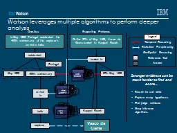
Slide37System AutonomyGoal: Establish system interfaces to provide autonomy algorithms with system information necessary and sufficient to manage system
Slide38Autonomy in Context: What and Why?38Spacecraft and Surface System Autonomy is the enabling capability for Human Exploration beyond Lunar Sortie MissionsAutonomy is necessary for complex system operationsTimely response to unplanned or unscheduled events
Propulsion, Structure, Thermal Conditioning, ECLSS, Electrical Power, Avionics, RCS, Communication are all understood sufficiently to allow engineered solutions to be reliably producedChallenges do exist in terms of Space Environmental Effects, efficiency, compact sizeRadiation Hardened computer processors neededPhysics and demonstrated solutions are available from which to engineer a vehicleOperations are sufficiently understood for terrestrial based execution, not on-board execution
Manual operations provide a rich knowledge base of planning and execution processes
Manual operations have a generic template (derived from Apollo/Saturn) applied uniquely to each spacecraft
Terrestrial based manual operations will not support operations beyond 5 light minutes from Earth
Autonomous Operations are essential to Human Exploration of the Solar System
Slide39Subsystem Management Functions for System Control
Performance
Diagnostics
Prognostics
Monitoring
Control
Subsystem
Slide40Autonomy System Stack
System
System Control
ISHM
Vehicle Control
Vehicle ISHM
Mission Execution
Mission Objectives & Constraint Data
Mission Planning
Detection
Diagnostics
Prognostics
Actuation
Control Logic
3 Levels
Mission Execution and Planning
Vehicle Management
Subsystem Integration Based
Physics form basis of subsystem interactions
Form basis of normal or failed states
Subsystem Level
Physics based
Slide41System Design and OptimizationGoal: Apply system design and optimization tools to understand and engineer system interactions
Slide42Multidisciplinary Design OptimizationMartins, J. R R. A., Lambe, A. B., “Multidisciplinary Design Optimization: A Survey of Architectures”, AIAA Journal
, Vol. 51,No. 9, September 2013, pp 2049 – 2075
Slide43Engineering StatisticsGoal: Utilize statistical methods to understand system uncertainties and sensitivitiesSystems Engineering makes use of Frequentist Approaches, Bayesian Approaches, Information Theoretic Approaches as appropriate
Slide44Optimal Sensor InformationConfigurationApplying Akaike Information Criteria (AIC) corrected (AICc) to assess sensor coverage for a systemTwo Views of Information ContentAIC InformationInformation is viewed as the number of meaningful parameters
Parameters with sufficient measurements to be reasonable estimatesFisher Information MatrixDefines information as the matrix of partial second derivativesInformation is the amount of parameters with non zero values (so provides an indication of structure)This value converges to a maximum as the number of parameters goes to infinityDoes not contain an optimum, always increases with added parameters
AIC/
AICc
has an adjustment factor to penalize sensor arrangements where:
number of sensors < 3x(number of measurements)
Provides an optimization tool for use with System Models
44
Slide45Flat Plate FEA Analysis and Akaike Information Criterion (AIC)
Slide - 45
Results
Sources of AICc:
Bias:
mean square error (MSE)
Total Corrections: “penalties” for over-fitting
Bias
Bias Correction
Small Sample Correction
Total Corrections
MWEI ‘Best’ is worst bias and
Slide46Verification ProcessMethod 1: ‘Intelligent’ GuessSlide - 46Final Solution:
Exergy-Based Information for Systems Analysis, Doty
Overlaid on Peaks
Projected to XY plane
Note:
2 initial guesses ‘removed’ (red)
NEW points added (blue)
MOST
initial guesses ‘survive’ (
green)
Slide47Sensor LocationSensor Placement is determined by locations of highest residual errorIndicates lowest level of information about the systemSystem model allows determination of highest residual error locationMust properly model physics of the system to be measured and associated interactionsPlacing the first sensor here changes the information available and biases all other locationsProvides keystone for locating sensors appropriatelyProvides an objective method to determine proper sensor measurement locations
47
Slide48Methods of System IntegrationGoal: System Design and Analysis
Slide49System Models Contain an Understanding of the SystemGoal Function
Tree (GFT)
Goals
Value Model
System State Transition
Model
System Functions &
State Variables
System Integrated
Physics Model
(System Exergy)
Discipline Physics
Models
System Functions &
State Variables
Engineering
Statistics
State
Variables
Multidisciplinary Design
Optimization (MDO)
MagicDraw
Enterprise (
SysML
)
Matlab
Matlab
StateFlow
Microsoft
Excell
Allow systems engineers to:
Define system functions based on the system state variables
Understand stakeholders expectations on system value (i.e., capabilities)
Integrate discipline engineering models into a system level physics based model (e.g., system exergy)
Design and Analyze system responses and behaviors at the System level
Slide50System Design and Integration
Slide51Methods of Engineering Discipline IntegrationGoal: Understand How Organizational Structures influence Design and Operations Success of Complex Systems
Slide52Sociological Concepts in Systems EngineeringSpecification of Ignorance is important in the advancement of the understanding of the systemConsistent use of Terminology is important for Communication within the OrganizationOpportunity StructuresProvide opportunity to mature ideasTask teams, working groups, communities of practice, etc.Socially Expected Durations will exist about the projectBoth Manifest and Latent Social Functions exist in the organization
Social Role SetsIndividuals have a set of roles for their positionCultural Subsets will formi.e., disciplines can be a subset within the organizationInsider and Outsider attitudes can formBe Aware of the Self-Fulfilling Prophecy, Social Polarization
Reconsiderations Process (i.e.,
Reclama
Process)
Provides ability to manage social ambivalence
Must be able to recognize social beliefs that may be contributing to the disagreement
Helps to avoid putting people in to social dysfunction or complete social anomie
Conformity
Innovation
Ritualism
Retreatism
Rebellion52
Slide53Information FlowInformation Flow through a program/project/activity is defined by Information TheoryOrganizational communication pathsBoard StructureDecision Making follows the First PostulateDecision Process is specific to the decision being madeTracked 3 SLS CRs, with 3 separate task team processes, all had equally rated effectiveness
53
Margin is maintained by the Organization, not in the margin management tables
Biased Information Sharing
Margin Management is focused on Managing the Disciplines (informed by the System Integrating Physics)
SLS Organizational Structure was defined by the LSE as a recommendation to the Chief Engineer and the Program Manager
Slide54Decision Structure Information FlowInformation Theory ModelInformation Theory can be used to understand decision making structures and information flow
Practitioner’s Guidance
Understand and define the scope of each needed decision body
Ensure that each decision body has all affected or contributing disciplines represented, including understanding of the types and magnitudes of uncertainties affecting decisions within that decision body’s
scope, but no more
Minimize
the number of decision bodies based on scope. The efficiency of the structure decreases with distributed and overlapping scopes.
54
Slide55SLS Organizational Structure ModelingInterviewed 12 Marshall engineers/designers (w/J. Shelton)Understand strategies used to integrate subsystems with each otherCommon strategy across subsystems – marginsKeep some percentage of a parameter in “back pocket” as hedge for future negotiationsBiased Information Sharing(Here, “margins” different from “safety margin”)How does maintaining a margin affect optimality of the final design?Model as simple 2 Player System with 3 design parameters
15 problem test suite
55
Slide56Simulation Results No margin :
Slide -
56
Static margin, m= 1.3
Descending margin
, 𝑚=1.3−.1∗𝑖 until 𝑚=1
No margin condition reaches optimality quickest
Descending margin still reaches optimal, but requires more iterations
Margins
are an
issue
Interviews
highlight real-world
consequences
Simulations
quantify extent of the
problem
Still possible to achieve optimal design with descending margin, but takes additional time to achieve
Slide57Discipline Integration Models
Goal Function Tree (GFT)
Organizational
Structure &
Mapping
System Functions
MagicDraw
Enterprise (
SysML
)
Matlab
Matlab
StateFlow
JAVA
Anylogic
Extend
Allow systems engineers to:
Understand information flow through the development and/or operations organization
Integrate discipline information into a system level design
Analyze information flow, gaps, and blind spots at the System level
Agent Based Model (ABM)
System Dynamics Model
Goals
Value Model
Value
Attributes
Discrete Event Simulation
Organizational
Values
Slide58System DynamicsGoal: Understand how information about the system flows through the organization and into the design and operations
Slide59Tools and Methodologies
Tools and techniques have been developed using the System Dynamics methodology that make it possible to efficiently decompose complex systems and to quickly set-up and test models of system operation.
Tools promote understanding through visual diagramming and modeling.
Slide60STS-ISS Transportation / Operation Analysis
Slide61ISS-STS Transportation / Operations Analysis
Slide62Policy and Law AssessmentsGoal: Understand How Policy and Law Constrain the Design and Operations of a System and How the System Engineer Should Interpret These Constraints
Slide63Space Policy andSystems EngineeringImpact of Government Oversight Time Allocation StudyMotivation: Industry and government leaders agree that government oversight leads to cost growth, but there is less agreement on how much and through what mechanisms.Research Plan:Build an empirical basis for measuring the extent and nature of the impact of oversightNon-invasive “Time Allocation Study:” Statistically valid aggregated observations of how engineers actually spend their time throughout a product’s life cycle.Part One: Collect time-recall diaries to develop a composite list of activities performed
Part Two: Survey Population over several months at random times per day to accurately observe amount of time spent on activitiesData collection is complete and analysis is in processMost non-value added oversight is internal company drivenGovernment generated insight/oversight is a small % of work done (< 10%)Corporate Communication and Administrative work drive non-value added work from viewpoint of practicing systems engineers within the company
63
Slide64Percentage of total time spent on each oversight category64Brainard, S. M.,
Zsajnfarber, Z., “Understanding the burden of government oversight on engineering work: adding empirical data to the debate”, submitted to Space Policy
Slide65System Engineering Supporting ActivitiesProcess Application and Execution for the Specific System
Slide66ProcessesWell defined in NASA/SP-2007-6105 Rev1, NASA Systems Engineering HandbookSEMP is essential to capture appropriate application of processes to the specific systemProcess application is specific to the system being developedTailoring is not a special exception, it is the norm
Slide67System Engineering Standards in Practice
67
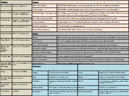
Slide68UAH SE Consortium - Comparing the Relationship between Systems Engineering Process and Project Success in Commercial and Government Research and Development Efforts, 2012 – 2014.
Processes with
>
3
Correlations ≥
.4
Processes with < 3
Correlations ≥ .4
Original Study
Correlations
68AgricultureAerospaceDefense and securityTransportation
Communications
Electronics
Energy
Infrastructure
Slide69UAH SE Consortium - Comparing the Relationship between Systems Engineering Process and Project Success in Commercial and Government Research and Development Efforts, 2012 – 2014.
Processes with
>
3
Correlations ≥
.4
Processes with < 3
Correlations ≥ .4
Original Study
Correlations
69
Slide70SummaryDiscussed approach to Engineering an Elegant SystemSystems Engineering Framework and PrinciplesSystem IntegrationEngineering Discipline IntegrationSeveral methods and tools are available for conducting integrated system design and analysisSystem IntegrationSystem State VariablesGoal Function TreeState Analysis Model
System Value ModelSystem Integrating PhysicsSystem AutonomyMultidisciplinary Design Optimization (MDO)Engineering StatisticsDiscipline IntegrationSociological Concepts in Systems Engineering
Information
Flow
Systems Thinking (Cognitive Science)
Policy and Law
System Dynamics Modeling
Systems Engineering Approach defined in two documents
“Engineering Elegant Systems: Theory of Systems Engineering”
“
Engineering Elegant Systems: The Practice of Systems Engineering
”
Send requests for documents to: michael.d.Watson@nasa.gov70