

L a t h e Turning Operations Machine Tool LATHE Job workpiece rotary motion Tool linear motions Mother of Machine Tools Cylindrical and flat surfaces Some Typical Lathe Jobs ID: 388318
Download Presentation The PPT/PDF document "Turning Operations" is the property of its rightful owner. Permission is granted to download and print the materials on this web site for personal, non-commercial use only, and to display it on your personal computer provided you do not modify the materials and that you retain all copyright notices contained in the materials. By downloading content from our website, you accept the terms of this agreement.


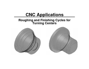


Slide1
Turning Operations
L a t h eSlide2
Turning Operations
Machine Tool – LATHE Job (workpiece) – rotary motionTool – linear motions
“
Mother of Machine Tools “
Cylindrical and flat surfacesSlide3
Some Typical Lathe Jobs
Turning/Drilling/Grooving/Threading/Knurling/Facing...Slide4
The LatheSlide5
The Lathe
Bed
Head Stock
Tail Stock
Carriage
Feed/Lead ScrewSlide6
Main Parts
BedHeadstockFeed and lead screwsCarriageTailstock
6Slide7
Lathe Bed
Heavy, rugged castingMade to support working parts of latheOn top section are machined waysGuide and align major parts of lathe
7Slide8
Lathe Bed
8Slide9
Headstock
Clamped on left-hand end of bedHeadstock spindleHollow cylindrical shaft supported by bearingsProvides drive through gears to work-holding devices
Live center, faceplate, or chuck fitted to spindle nose to hold and drive work
Driven by stepped pulley or transmission gears
Feed reverse lever
Reverses rotation of feed rod and lead screw
9Slide10
Headstock
10Slide11
Headstock
11
Back Gear arrangement
Headstock belt driveSlide12
Quick-Change Gearbox
Contains number of different-size gearsProvides feed rod and lead-screw with various speeds for turning and thread-cutting operationsFeed rod advances carriage when automatic feed lever engagedLead screw advances the carriage for thread-cutting operations when split-nut lever engaged
12Slide13
Quick-Change Gearbox
13Slide14
Carriage
Used to move cutting tool along lathe bedConsists of three main partsSaddleH-shaped casting mounted on top of lathe ways, provides means of mounting cross-slide and apronCross-slide
Apron
14Slide15
15
Carriage
< Saddle
< ApronSlide16
Carriage
16Slide17
Carriage
17Slide18
18
Apron
The apron attached to the front of the carriage, holds most of the control levers. These include the levers, which engage and reverse the feed lengthwise (Z-axis) or crosswise (X-axis) and the lever which engages the threading gears.
The apron is fastened to the saddle, houses the gears and mechanisms required to move the carriage and cross-slide automatically.
The apron hand wheel can be turned manually to move the carriage along the Lathe bed. This hand wheel is connected to a gear that meshes in a rack fastened to the Lathe bed.
The automatic feed lever engages a clutch that provides the automatic feed to the carriageSlide19
Cross-slide
Mounted on top of saddleProvides manual or automatic cross movement for cutting toolCompound rest (fitted on top of cross-slide)
Used to support cutting tool
Swiveled to any angle for taper-turning
Has graduated collar that ensure accurate cutting-tool settings (.001 in.) (also cross-slide)
19Slide20
Cross-slide
20Slide21
21Slide22
Top Slide (Compound slide)
Fitted to top of Cross slideCarries tool post and cutting toolCan rotate to any angleIs used to turn tapers
22Slide23
Tailstock
Upper and lower tailstock castingsAdjusted for taper or parallel turning by two screws set in baseTailstock clamp locks tailstock in any position along bed of latheTailstock spindle has internal taper to receive dead center
Provides support for right-hand end of work
23Slide24
24
Tailstock
Supports long
workpieces
when machining.
60 degree rotating center point.
Drill Chuck
Turn the tailstock handwheel to advance the ram.Slide25
Tailstock
25Slide26
Lead Screw and Feed Rod
26
< Lead
Screw
< Feed RodSlide27
Types of Lathes
Engine LatheSpeed LatheBench LatheTool Room LatheSpecial Purpose Lathe
Gap Bed Lathe
…Slide28
Size of Lathe
Workpiece Length
SwingSlide29
Size of Lathe ..
Example: 300 - 1500 LatheMaximum Diameter of Workpiece that can be machined = SWING
(= 300 mm)
Maximum Length of Workpiece that can be held between Centers (=1500 mm)Slide30
Workholding Devices
Equipment used to holdWorkpiece – fixturesTool - jigs
Securely
HOLD
or
Support
while machiningSlide31
Chucks
Three jaw Four Jaw
Workholding Devices
..Slide32
32
ChucksUsed extensively for holding work for lathe machining operations
Work large or unusual shape
Most commonly used lathe chucks
Three-jaw universal
Four-jaw independent
Collet chuckSlide33
33
Three-jaw Universal Chuck
Holds round and hexagonal work
Grasps work quickly and accurate within few thousandths/inch
Three jaws move simultaneously when
adjusted by chuck wrench
Caused by scroll plate into which all three jaws fit
Two sets of jaw: outside chucking and inside chuckingSlide34
34
Three-jaw Universal ChuckSlide35
35
Three jaw self centering chuckSlide36
36
Four-Jaw Independent Chuck
Used to hold round, square, hexagonal, and irregularly shaped workpieces
Has four jaws
Each can be adjusted independently by chuck wrench
Jaws can be reversed to hold work by inside diameterSlide37
37
Four-Jaw Independent ChucksSlide38
Four-Jaw Independent Chucks
38
With the four jaw chuck, each jaw can be adjusted independently by rotation of the radially mounted threaded screws.
Although accurate mounting of a workpiece can be time consuming, a four-jaw chuck is often necessary for non-cylindrical workpieces. Slide39
Mandrels
Workpiece (job) with a hole
Workholding Devices
..Slide40
Mandrels
40
Holds internally machined workpiece between centers so further machining operations are concentric with bore
Several types, but most common
Plain mandrel
Expanding mandrel
Gang mandrel
Stub mandrelSlide41
41
Mandrels to Hold Workpieces for Turning
Figure 23.8 Various types of mandrels to hold workpieces for turning. These mandrels usually are mounted between centers on a lathe. Note that in (a), both the cylindrical and the end faces of the workpiece can be machined, whereas in (b) and (c), only the cylindrical surfaces can be machined.Slide42
Rests
Workholding
Devices
..
Steady Rest Follower RestSlide43
43
Steadyrest
Used to support long work held in chuck or between lathe centers
Prevent springing
Located on and aligned by ways of the lathe
Positioned at any point along lathe bed
Three jaws tipped with plastic, bronze or rollers may be adjusted to support any work diameter with steadyrest capacitySlide44
44
SteadyrestSlide45
45
Follower Rest
Mounted on saddle
Travels with carriage to prevent work from springing up and away from cutting tool
Cutting tool generally positioned just ahead of follower rest
Provide smooth bearing surface for two jaws of follower restSlide46
46
Follower RestSlide47
Operating/Cutting Conditions
Cutting Speed vFeed f
Depth of Cut
dSlide48
Operating ConditionsSlide49
Cutting Speed
The Peripheral Speed of Workpiece past the Cutting Tool =Cutting Speed
Operating Conditions
..
D
– Diameter (mm)
N
– Revolutions per Minute (rpm)Slide50
Feed
f – the distance the tool advances for every rotation of workpiece (mm/rev)
Operating Conditions
..Slide51
Depth of Cut
perpendicular distance between machined surface and uncut surface of the Workpiece d = (D1 –
D
2
)/2 (mm)
Operating Conditions
..Slide52
3 Operating ConditionsSlide53
Selection of ..
Workpiece Material Tool MaterialTool signature Surface FinishAccuracy
Capability of Machine Tool
Operating Conditions
..Slide54
Material Removal Rate
MRRVolume of material removed in one revolution
MRR =
D
d
f
mm
3
Job makes
N
revolutions/min
MRR
= D d
f
N
(mm
3
/min)
In terms of
v
MRR is given by
MRR
= 1000
v d f
(mm
3
/min)
Operations on Lathe
..Slide55
MRR
dimensional consistency by substituting the units
Operations on Lathe
..
MRR
:
D
d
f
N
(mm)(mm)(mm/rev)(rev/min)
= mm
3
/minSlide56
Operations on Lathe
TurningFacingknurling
Grooving
Parting
Chamfering
Taper turning
Drilling
Threading
Operations on Lathe
..Slide57
Turning
Cylindrical job
Operations on Lathe
..Slide58
Turning ..
Cylindrical job
Operations on Lathe
..Slide59
Turning ..
Excess Material is removed to reduce DiameterCutting Tool: Turning Tool
a
depth of cut
of 1 mm will reduce diameter by 2 mm
Operations on Lathe
..Slide60
Facing
Flat Surface/Reduce length
Operations on Lathe
..Slide61
Facing ..
machine end of job Flat surfaceor to Reduce Length of Job
Turning Tool
Feed
: in direction perpendicular to workpiece axis
Length of Tool Travel = radius of workpiece
Depth of Cut
: in direction parallel to workpiece axis
Operations on Lathe
..Slide62
Facing ..
Operations on Lathe
..Slide63
Eccentric Turning
Operations on Lathe
..Slide64
Knurling
Produce rough textured surfaceFor Decorative and/or Functional Purpose
Knurling Tool
A
Forming
Process
MRR
~0
Operations on Lathe
..Slide65
Knurling
Operations on Lathe
..Slide66
Knurling ..
Operations on Lathe
..Slide67
Grooving
Produces a Groove on workpieceShape of tool shape of groove
Carried out using
Grooving Tool
A
form tool
Also called
Form Turning
Operations on Lathe
..Slide68
Grooving ..
Operations on Lathe
..Slide69
Parting
Cutting workpiece into TwoSimilar to groovingParting ToolHogging – tool rides over – at slow feedCoolant use
Operations on Lathe
..Slide70
Parting ..
Operations on Lathe
..Slide71
Chamfering
Operations on Lathe
..Slide72
Chamfering
Beveling sharp machined edgesSimilar to form turningChamfering tool – 45
°
To
Avoid Sharp Edges
Make Assembly Easier
Improve Aesthetics
Operations on Lathe
..Slide73
Taper Turning
Taper:
Operations on Lathe
..Slide74
Taper Turning..
Methods
Form Tool
Swiveling Compound Rest
Taper Turning Attachment
Simultaneous Longitudinal and Cross Feeds
Operations on Lathe
..
ConicitySlide75
Taper Turning
..By Form Tool
Operations on Lathe
..Slide76
Taper Turning ,,
By Compound Rest
Operations on Lathe
..Slide77
Drilling
Drill – cutting tool – held in TS – feed from TS
Operations on Lathe
..Slide78
Process Sequence
How to make job from raw material 45 long x 30 dia.?
Operations on Lathe
..
Steps
:
Operations
Sequence
Tools
Process Slide79
Process Sequence ..
Possible Sequences
TURNING - FACING - KNURLING
TURNING - KNURLING - FACING
FACING - TURNING - KNURLING
FACING - KNURLING - TURNING
KNURLING - FACING - TURNING
KNURLING - TURNING – FACING
What is an Optimal Sequence?
Operations on Lathe
..
X
X
X
XSlide80
Machining Time
Turning TimeJob length Lj mmFeed f mm/rev
Job speed
N
rpmf N
mm/min
Operations on Lathe
..Slide81
Manufacturing Time
Manufacturing Time = Machining Time + Setup Time
+ Moving Time
+ Waiting Time
Operations on Lathe
..Slide82
Example
A mild steel rod having 50 mm diameter and 500 mm length is to be turned on a lathe. Determine the machining time to reduce the rod to 45 mm in one pass when cutting speed is 30 m/min and a feed of 0.7 mm/rev is used. Slide83
Example
calculate the required spindle speed as: N = 191 rpm
Given data:
D
= 50 mm,
L
j
= 500 mm
v
= 30 m/min,
f
= 0.7 mm/rev
Substituting the values of
v
and
D
inSlide84
Example
Can a machine has speed of 191 rpm? Machining time:
t
= 500 / (0.7
191)
= 3.74 minutesSlide85
Example
Determine the angle at which the compound rest would be swiveled for cutting a taper on a workpiece having a length of 150 mm and outside diameter 80 mm. The smallest diameter on the tapered end of the rod should be 50 mm and the required length of the tapered portion is 80 mm. Slide86
Example
Given data: D1 = 80 mm, D2 = 50 mm, Lj = 80 mm (with usual notations) tan
=
(80-50) / 2
80
or
= 10.620
The compound rest should be swiveled at 10.62
oSlide87
Example
A 150 mm long 12 mm diameter stainless steel rod is to be reduced in diameter to 10 mm by turning on a lathe in one pass. The spindle rotates at 500 rpm, and the tool is traveling at an axial speed of 200 mm/min. Calculate the cutting speed, material removal rate and the time required for machining the steel rod.Slide88
Example
Given data: Lj = 150 mm, D1 = 12 mm, D2 = 10 mm, N = 500 rpm
Using Equation (1)
v =
12
500 / 1000
= 18.85 m/min.
depth of cut =
d
= (12 – 10)/2 = 1 mmSlide89
Example
feed rate = 200 mm/min, we get the feed f in mm/rev by dividing feed rate by spindle rpm. That is f
= 200/500 = 0.4 mm/rev
From Equation (4),
MRR
= 3.142
12
0.4
1
500 = 7538.4 mm3/min
from Equation (8),
t
= 150/(0.4
500) = 0.75 min.Slide90
Example
Calculate the time required to machine a workpiece 170 mm long, 60 mm diameter to 165 mm long 50 mm diameter. The workpiece rotates at 440 rpm, feed is 0.3 mm/rev and maximum depth of cut is 2 mm. Assume total approach and overtravel distance as 5 mm for turning operation.Slide91
Example
Given data: Lj = 170 mm, D1 = 60 mm, D2 = 50 mm, N = 440 rpm,
f
= 0.3 mm/rev,
d= 2 mm,
How to calculate the machining time when there is more than one operation? Slide92
Example
Time for Turning:Total length of tool travel = job length + length of approach and overtravel
L
= 170 + 5 = 175 mm
Required depth to be cut = (60 – 50)/2 = 5 mm
Since maximum depth of cut is 2 mm, 5 mm cannot be cut in one pass. Therefore, we calculate number of cuts or passes required.
Number of cuts required = 5/2 = 2.5 or 3 (since cuts cannot be a fraction)
Machining time for one cut =
L
/ (
f
N
)
Total turning time = [
L
/ (
fN)] Number of cuts
= [175/(0.3440)] 3= 3.97 min.Slide93
Example
Time for facing: Now, the diameter of the job is reduced to 50 mm. Recall that in case of facing operations, length of tool travel is equal to half the diameter of the job. That is,
l
= 25 mm. Substituting in equation 8, we get
t
= 25/(0.3
440)
= 0.18 min.Slide94
Example
Total time: Total time for machining = Time for Turning + Time for Facing = 3.97 + 0.18
= 4.15 min.
The reader should find out the total machining time if first facing is done.Slide95
Example
From a raw material of 100 mm length and 10 mm diameter, a component having length 100 mm and diameter 8 mm is to be produced using a cutting speed of 31.41 m/min and a feed rate of 0.7 mm/revolution. How many times we have to resharpen or regrind, if 1000 work-pieces are to be produced. In the taylor’s expression use constants as
n
= 1.2 and
C = 180 Slide96
Example
Given D =10 mm , N = 1000 rpm, v = 31.41 m/minute
From Taylor’s tool life expression, we have
vT n
= C
Substituting the values we get,
(31.40)(
T
)1.2 = 180
or
T
= 4.28 minSlide97
Example
Machining time/piece = L / (fN
)
= 100 / (0.7
1000) = 0.142 minute.
Machining time for 1000 work-pieces = 1000
0.142 = 142.86 min
Number of resharpenings = 142.86/ 4.28
= 33.37 or 33 resharpenings Slide98
Example
6: While turning a carbon steel cylinder bar of length 3 m and diameter 0.2 m at a feed rate of 0.5 mm/revolution with an HSS tool, one of the two available cutting speeds is to be selected. These two cutting speeds are 100 m/min and 57 m/min. The tool life corresponding to the speed of 100 m/min is known to be 16 minutes with
n
=0.5. The cost of machining time, setup time and unproductive time together is Rs.1/sec. The cost of one tool re-sharpening is Rs.20.
Which of the above two cutting speeds should be selected from the point of view of the total cost of producing this part? Prove your argument.Slide99
Example
Given T1 = 16 minute, v1 = 100 m/minute,
v
2 = 57 m/minute,
D = 200mm, l = 300 mm, f
= 0.5 mm/rev
Consider Speed of 100 m/minute
N
1 = (1000
v
) / (
D
) = (1000100) / (200) = 159.2 rpm t1 =
l / (fN) = 3000 / (0.5 159.2) = 37.7 minute Tool life corresponding to speed of 100 m/minute is 16 minute.
Number of resharpening required = 37.7 / 16 = 2.35
or number of resharpenings = 2Slide100
Example
Total cost = Machining cost + Cost of resharpening Number of resharpening = 37.760
1+ 20
2 = Rs.2302Slide101
Example
Consider Speed of 57 m/minute
Using Taylor’s expression
T
2 = T1
(
v
1 /
v
2)2 with usual notations
= 16
(100/57)2 = 49 minute
Repeating the same procedure we get
t
2 = 66 minute, number of
reshparpening
=1 and total cost = Rs. 3980. The cost is less when speed = 100 m/minute. Hence, select 100 m/minute. Slide102
Example
Write the process sequence to be used for manufacturing the component
from raw material of 175 mm length
and 60 mm diameter Slide103
ExampleSlide104
Example
To write the process sequence, first list the operations to be performed. The raw material is having size of 175 mm length and 60 mm diameter. The component shown in Figure 5.23 is having major diameter of 50 mm, step diameter of 40 mm, groove of 20 mm and threading for a length of 50 mm. The total length of job is 160 mm. Hence, the list of operations to be carried out on the job are turning, facing, thread cutting, grooving and step turning Slide105
Example
A possible sequence for producing the component would be:Turning (reducing completely to 50 mm)Facing (to reduce the length to 160 mm)Step turning (reducing from 50 mm to 40 mm)
Thread cutting.
Grooving