
motors Armature Permanent Magnets Brushes Commutator Coils 2 PMDC motors animation 3 3 PMDC motors components 4 PMDC motors Stationary element is a permanent magnet Have commutator and brushes to switch current direction in armature ID: 920128
Download Presentation The PPT/PDF document "1 1 Permanent magnet (PM) DC" is the property of its rightful owner. Permission is granted to download and print the materials on this web site for personal, non-commercial use only, and to display it on your personal computer provided you do not modify the materials and that you retain all copyright notices contained in the materials. By downloading content from our website, you accept the terms of this agreement.


Slide1
1
1
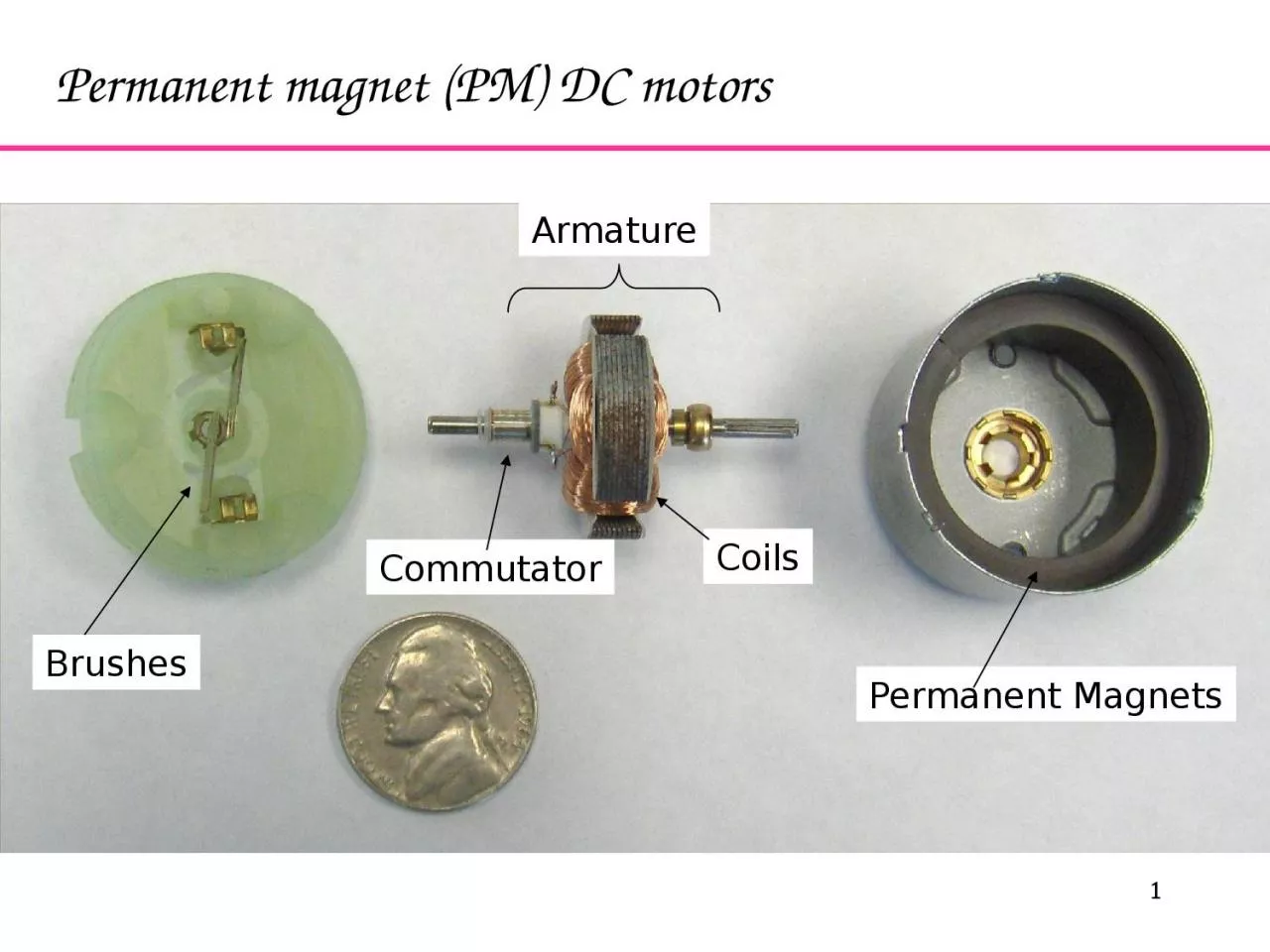
Permanent magnet (PM) DC motors
Armature
Permanent Magnets
Brushes
Commutator
Coils
Slide22
PMDC motors – animation
Slide33
3
PMDC motors – components
Slide44
PMDC motors Stationary element is a permanent magnetHave commutator and brushes to switch current direction in armatureLimited in size (large magnets are expensive)Low cost, low power, battery operationCommon in appliances, toys, RC
Electric Toothbrush
Slide55
Other types of DC motorsWound Stator Stationary element is an electromagnetConnected in series or parallel with armatureCommutator and brushesCan run on DC or AC current (universal motor)Brushless No brushes to wear out or cause electrical noise More complicated to controlUsed in computer disc drives, fans
shunt wound
series wound
Slide66
PMDC motorsTypical Uses: Small appliances, RC, often battery poweredOften used with position or velocity feedback (optical encoder or tachometer)Reduction gear heads commonEasy to control: Speed, Torque Input voltageSize Range: Micro 0.5” L x 0.2”D (pager vibrator) <$1
Big 13”L x 4”D 2 HP $1000
RPM
Torque
V
1
V2 >V1
Slide77
Basic principle of operation – a wire in a magnetic field will be feel a sidewise forceConductor in a magnetic field: (Fleming’s Rule)
N
S
B = magnetic flux density
I = current
Force = I L B
F = force
Permanent
Magnet
L = length of wire
in the magnetic field
Slide88
In a motor, we have coils of wires, so the force becomes a momentFor each turn of the coil:
B
F
I
Torque = 2rBIL
r
Slide99
If you want to get more torque out of motor:Increase L – more coils, longer armatureStronger magnetic field (B) – use stronger magnets (typical RC airplane motors use “rare earth” magnets)Increase current (I) – increase input voltageIncrease armature diameter, (r)
Slide1010
Typical PMDC motor performance curves (available from the manufacturer, or by test)
Efficiency
Torque
Current
Power
Out
Power In
0wMAX
TSTALLiSTALL
i
@max
Constant V
Slide1111
Manufacturer’s data sheet
Slide1212
η
Torque
W
Operates with
max power at this speed
½ No Load Speed
No Load Speed
Max Efficiency @ this speedWhat is your design objective - maximum power or maximum efficiency?
Slide1313
To size the motor, we need to know what it is driving, i.e. the “load” curve
Rotational Speed
Torque
0.5 gpm
1 gpm
2 gpm
4 gpm
8 gpm
Typical load curvefor a pump and
plumbing system, a fan load curve is similar
Slide1414
The intersection of the load curve and the motor curve will determine the operating speed of the motor
Rotational Speed
Torque
Load
Larger Motor
Motor A
Motor A with
2:1 reduction
Slide1515
Other concernsMotor Life: Internal losses (resulting in heat) ~ I2 This determines the maximum steady state currentHigh temperature can demagnetize magnets, melt insulationTypical gear efficiency: 70-80% for each stage
Slide1616
Noise suppression capacitors
Slide1717
Brushless motors Stationary coils that are electrically commutatedRotating permanent magnetsIn-runner – magnetic core inside coilsOut-runner – magnetic cup outside coilsSense rotor angle using Hall effect sensors or EMF in non-powered coilsTypically three coils wired as Wye or DeltaBidirectional coil drivers
Slide1818
Brushless motors – stator coils, rotor PM
Slide1919
Brushless motors - commutation
Slide2020
Brushless motors - commutation
Slide2121
Brushless motor – in-runner
Slide2222
22
Brushless motor – out-runner
Magnetic
sensor
Magnet
Stationary
Coils
Circuitry to
switch coil polarity
Slide2323
Brushless motors – out-runner
Slide2424
Brushless motors – out-runner
Slide2525
Brushless motors – pancake
Slide2626
Brushless motors – printed rotor
Slide2727
Brushless motors – printed rotor
Slide2828
Batteries – typesAlkaline (C, AA, AAA, 9V)1.5V per cell, cheap, generally not rechargeableLead acid (automotive)12V, sulphuric acid, never below 10.5VSealed lead acid (SLA) - gel cell, absorbed glass mat (AGM)6V or 12V, any orientation, never below 10.5V for 12VNiCd (nickel-cadmium)1.2V per cell, may discharge completelyNiMH (nickel-metal-hydride)1.2V per cell, NEVER discharge completely, self-dischargeLiPo (lithium-polymer)dangerous charge/discharge, limited cycles ~300LiFePO4 (lithium-iron-phosphate)safer, more cycles ~1000
Slide2929
Batteries – energy density
Slide3030
Batteries – energy density
Slide3131
Batteries – ratingAmp-hours (Ah)Constant discharge current multiplied by discharge time before reaching minimum recommended voltageC20 rating is Ah available for 20 hoursExample: 12V gel-cell battery with 18 Ah rating can provide 0.9 A current continuously for 20 hours before reaching 10.5V minimum threshold
Slide3232
Batteries – discharge curvesLead acidMore linear voltage versus time discharge curveHigher discharge rate reduces capacity (Peukert’s Law)Example: 12V gel-cell battery with 7 Ah C20 rating0.35 A discharge, 20 hours = 7 Ah0.65 A discharge, 10 hours = 6.5 Ah1.2 A discharge, 5 hours = 6.0 Ah4.2 A discharge, 1 hours = 4.2 AhNiCdFlatter voltage versus time discharge curveMore difficult to monitor remaining capacityDischarge rate does not reduce capacity as much as lead acid
Slide3333
12V 18Ah sealed lead acid (SLA)
Slide3434
12V 18Ah sealed lead acid (SLA)
Slide3535
Harbor Freight 18V NiCd battery pack
Slide3636
Ryobi 18V NiCd Battery Pack
Slide3737
Alkaline discharge curves
Slide3838
NiMh and LiPo discharge curves