PPT-Logical Organization Of Computer-2
Author : melody | Published Date : 2023-11-08
BCA 2 nd S em By Mrs Meenu Nangia HIMTRohtak Addressing Modes The operation field of an instruction specifies the operation to be performed This operation
Presentation Embed Code
Download Presentation
Download Presentation The PPT/PDF document "Logical Organization Of Computer-2" is the property of its rightful owner. Permission is granted to download and print the materials on this website for personal, non-commercial use only, and to display it on your personal computer provided you do not modify the materials and that you retain all copyright notices contained in the materials. By downloading content from our website, you accept the terms of this agreement.
Logical Organization Of Computer-2: Transcript
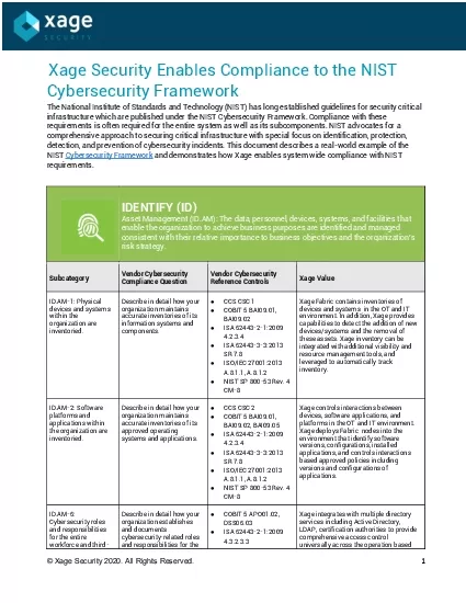
BCA 2 nd S em By Mrs Meenu Nangia HIMTRohtak Addressing Modes The operation field of an instruction specifies the operation to be performed This operation will be executed on some data which is stored in computer registers or the main memory The way any operand is selected during the program execution is dependent on . H Bennett Logical Reversibility of Computation Abstract The usual generalpurpose computing automaton eg a Turing machine is logically irreversible its transition function lacks a singlevalued inverse Here Crescendo leverages its stateoftheart smart card platform technology to deliver a standardbased solution for strong authentication and data protection Crescendo smart cards also address evolving market needs by o57375ering superior performance and s Crescendo leverages the stateof theart smart card platform technology to deliver a standardsbased solution for strong authentication and data protection The smart cards also address evolving market needs by o57375ering superior performance and secur Mario G 132 merry’ folws by logical necessity the conclusion ‘Some women are merry’. Note that these eamples also lie far from the lines that divide the instances from the non-instance Decision Structures: The . If-Else If . Statement, . Nested If Statements, Logical Operators, and String Comparison. Review. In a . decision structure. ’s simplest form certain statements are executed only . -. T. olerant Quantum Computation in Multi-. Qubit. Block Codes. Todd A. Brun. University of Southern California. QEC 2014, Zurich, Switzerland. With . Ching. -Yi Lai, Yi-Cong . Zheng. , Kung-. Chuan. Operating Systems. CS550. Memory Manager. Memory . manager - manages allocation and . de-allocation . of main . memory. Plays significant impact on operating system . because it is. . so important to . Communication. Social Styles. Analytical . Driving. Expressive. Amiable. Social Styles. Logical. Reserved. Thoughtful. Thorough. Social Styles. Direct. Determined. Guarded. Set the Pace. Social Styles. Logic. Logos/logic is situated (bound/defined by a cultural space). . In Philosophy, there are “traditions” of logic, and a study of various forms of logic including logics that don’t use language at all. . Carsten Schürmann. DemTech. April 8, 2015. IEEE-SA VSSC-1622.6. Objective. Implementation. Administrative Processes. Software. Legislation. Law. Logical Framework. Data. Computation. Logic. Properties. A. B. C. a = qb+r gcd(a,b) = gcd(b,r). Basic Information. Course . homepage. : . http://www.cse.iitd.ac.in/~naveen/teaching/courses/COL202/. Instructor. : . Naveen . Garg. Teaching Assistants. . by Auguste Rodin. Rationalism. in its modern sense, . rationalism. is any view appealing to reason as a source of knowledge or justification. it is a method of justifying beliefs in which the criterion of the truth is not sensory but intellectual and logical. access management with Single Sign-on SSO and Multi-Factor Authentication MFA universally across the operation with full visibility for auditability With Xage organizations can unify identity and acce Computer Lab Rules. Report to class on time. If you are not in class when the bell rings. , report . to counselor for pass/detention. Computer Lab Rules. Stay in assigned seats. You are accountable for the computer which is assigned to you.
Download Document
Here is the link to download the presentation.
"Logical Organization Of Computer-2"The content belongs to its owner. You may download and print it for personal use, without modification, and keep all copyright notices. By downloading, you agree to these terms.
Related Documents