
Conference for Engineering Education and Technology Soctt Braille Learning Blocks System 46 26 July 2019 Montego Bay Jamaica 1 Smart Braille Learning Blocks System Niki Taheri ID: 938175
Download Pdf The PPT/PDF document "17th LACCEI International Multi" is the property of its rightful owner. Permission is granted to download and print the materials on this web site for personal, non-commercial use only, and to display it on your personal computer provided you do not modify the materials and that you retain all copyright notices contained in the materials. By downloading content from our website, you accept the terms of this agreement.


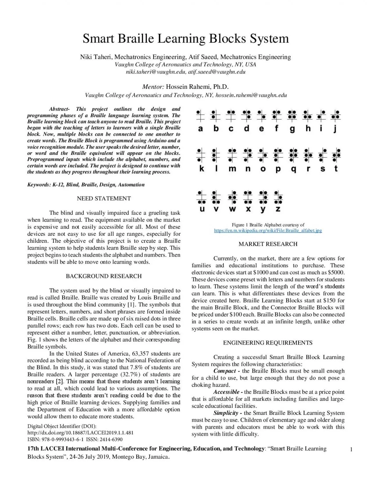
17th LACCEI International Multi - Conference for Engineering, Education, and Technology : “Soctt Braille Learning Blocks System ”. 46 - 26 July 2019, Montego Bay, Jamaica . 1 Smart Braille Learning Blocks System Niki Taheri, Mechatronics Engineering, Atif Saeed, Mechatronics Engineering Vaughn College of Aeronautics and Technology, NY, USA niki . taheri@vaughn . edu, atif . saeed@vaughn . edu Mentor: Hossein Rahemi, Ph . D . Vaughn College of Aeronautics and Technology, NY, hossein . rahemi@vaughn . edu Abstract - This project outlines the design and programming phases of a Braille language learning system . The Braille learning block can teach anyone t o read Braille . This project began with the teaching of letters to learners with a single Braille block . Now , multiple blocks can be connected to one another to create words . The Braille B lock is programmed using Arduino and a voice recognition module . The user speak s the desired letter, number, or word and the Braille equivalent will appear on the blocks . P reprogrammed inputs which include the alphabet, numbers, and certain words are included. The project is designed to continue with the students as they progress throughout the ir learning process . Keywords: K - 12 , Blind , Braille , Design, Automation NEED STATEMENT T he blind and visually impaired face a grueling task when learning to read . The equipment available on the market is expensive and not easily accessible for all . Most of these devices are not easy to use for all age ranges, especially for children . The objective of this project is to create a Braille learning sys tem to help students learn Braille step by step . This project begin s to teach students the alphabet and numbers . Then students will be able to move onto learning words . BACKGROUND RESEARCH The system used by the blind or visually impaired to read is called Braille . Braille was created by Louis Braille and i s used throughout the blind community [1] . The symbols that represent letter s , numbers, and short phrases are formed inside Braille cells . Braille cells are mad e up of six raised dots in t hree parallel rows ; each row ha s two dots . Each cell can be used to represent either a number, letter, punctuation, or abbreviation . Fig. 1 shows the letters of the alphabet and their corresponding Braille symbol s . In the United States of America, 63,357 students are recorded as being blind according to the National Federation of the Blind. In this study, it was stated that 7.8% of students a re Braille readers. A larger percentage (32.7%) of students are poptgcfgts [4]0 Tjis ogcps tjct tjgsg stufgpts ctgp’t ngctpipi to read at all, which could lead to various assumptions. The tgcsop tjct tjgsg stufgpts ctgp’t tgcfipi eounf dg fug to tjg high p rice of Braille learning devices. Supplying families and the Department of Education with a more affordable option would allow them to educate more students. Figure 1 Braille Alphabet courtesy of https://en.m.wikipedia.org/wiki/File: Braille _alfabet.jpg MARKET RESEARCH Currently, on the market , there are a few options for families and educational institutions to purchase . The se electronic devices start at $1000 and can cost as much as $5000 . These devices come preset with letters and numbers for students to learn . Th ese systems limit the length of the wotf’s stufgpts can learn . This is what differentiates these devices from the device created here . Braille Learning Block s start at $150 for the main Braille Block , and the C onnector Braille Blocks will be priced under $100 each . B raille Blocks can also be connected in a series to create words at an infinite length, unlike other systems seen on the market . ENGINEERING REQUIREMENTS Creating a successful Smart Braille Block Learning System require s the following characteristics: Compact - the Braille Blocks must be small enough for a child to use , but large enough that they do not pose a choking hazard . Accessible - t he Braille Blocks must be at a price point that is affordable for all markets inclu ding families and larg e - scale educational facilities. Simplicity - t he Smart Braille Block Learning System must be easy to use. Child ren of elementary age and older along with parents and educators must be able to work with this system with little difficulty. 17th LACCEI International Multi - Conference for Engineering, Education, and Technology : “Soctt Braille Learning Blocks System ”. 46 - 26 July 2019, Montego Bay, Jamaica . 2 DESIGN CONCEPT In the Braille system , each cell is made up of six raised dots in three parallel rows , each row with two dots . For each number, letter, or punctuation a variable pattern is made . When combined, these Braille cells can create words and even create math equations . With the knowledge that six raised dots in three parallel rows are the main focus of this project . I t i s identified that a physical actuator need s to be used to represent the dots . For the device to have power , the main Braille block must be plugged into a wall outlet . This Smart Braille Learning Block System is unique in that it uses voice recognition to activate the Braille cells . The Voice Recognition Module pre - records sounds, which can later be accessed by the Arduino Uno . When an input is heard, the Arduino compares that input with the prerec orded inputs in the database. Once a match is achieved the corresponding solenoids are actuated. The structure of this device is designed to be used by young children and adults of all age ranges . The Braille Block s are rectangular shape and are large enou gh to be used by a small child without any difficult y (Fig. 2) . Each block represent s a single Braille c ell, with six dots that raise and lower to express the desired output . Each dot is actuated using a small 5V solenoid . Figure 2 Braille Block WORKING MECHANISM OF DESIGN When designing the Braille Learning Block System , two aspects were kept in mind ; the device needs to be affordable and easy to use for all age ranges . Each Braille Block must contain a total of six small solenoids . Each solenoid represents a dot in the Braille cell . The solenoids are placed in the same configuration as a Braille cell, three parallel rows of two . The Braille Learning Blocks are connected in series using magnet ic strips . These magnet ic s trips work by acting as a conduct or , transferring power from the main Braille Block to the connector blocks . There are unlimited possibilities for displaying out puts by the user r anging from a single letter to a
large complicated multi - syllab ic word . The operation of the Braille L earning B locks is simple . The main Braille Blo c k is plugged into a 110V outlet. The user can add additional connecting blocks as desired . These blocks are connected in series via the magnetic strips on the sides of each block . Once the Braille Learning Blocks are connected in series, the user says a word to activate the voice recognition module, and the Braille Block Learning System displays the word in Braille . Now the user can feel the dots for each letter that make the word . The Braille Learning Block System will change when the user says another word. When finished simply unplug the main Braille Block from the outlet. As mentioned earlier , the main Braille Block has the functionality to connect one or more Braille Learning Blocks in a series to make simple words, Fig. 3, or connect additional blocks to create multi - syllabic complex words. Hav ing the Braille Learning Blocks connected together allows the user to further expand his or her knowledge o f reading Braille by creating longer and more complex words. Figure 3 Three Braille Blocks Connected MANUFACTURED PARTS T wo manufactured components make up the Braille Block. Both of these parts components are designed in Inventor and 3D printed using the Ultimaker 3 and the filament used is P olylactic A cid (PLA) . Since these components are used by children, a strong material, like PLA, is needed to withstand the environment that the device will be used in. When creating the components , the first designed was the body. The body house s all the electrical components including the microcontroller, the actuators, the circuit, and the voice reco gnition module. T he Braille Block also need s to be kept in the constraints of the typical Braille block cell , which means that the shape of the Braille Block must be a rectangular prism. The dimensions of the Braille Block Body are 74 .5 mm length , 3 6 .85 mm wide, and 3 3.65 mm tall with a wall thickness of 3. 175 mm . The size of the box is determined to be small 17th LACCEI International Multi - Conference for Engineering, Education, and Technology : “Soctt Braille Learning Blocks System ”. 46 - 26 July 2019, Montego Bay, Jamaica . 3 enough for an adult to use and large enough not to create a choking hazard for small children. The design of the body of the Braille Block body can be seen in Fig. 4 . S ix actuators are attached to the inside of the Braille Block using glue . It was determined to use glue instead of screw s to secure the actuators into the Braille Block to avoid creating a choking hazard. The Braille Block includes the six actuators that are necessary for making a complete Braille cell . Fig. 4 shows the actuators in the block. The additional space is saved for the remaining components required for the Braille Block circuit . Figure 4 Bottom of Braille Block T he lid of the Braille Block (Fig. 5) has six holes in which the actuators can rise through. These holes are 7. 8 mm in diameter , which allow for the actuators to fully emerge from the lid. The measurements from the center of one hole to the center of an adjacent hole is 14.35 mm ; this dimension allow s for the most compact size while allowing sufficient space for wires to be routed around the solenoids . Figure 5 the Lid of Braille Block Th e lid is where the user will be able to feel the outputted symbo l . To help exaggerate the dots, 3D designed caps are placed on top of the actuators. These caps will allow the use r to have a better feeling of how the Braille symbol outputted will feel. Fig. 6 shows the design of the lid with the caps . The lid fits tightl y to the body of the Braille Block; no entry to the inside electronics is necessary by the user. The main Braille Block and the connecting Braille Blocks have the same design. Figure 6 Caps of the Actuators The entire Braille Block is 74 .5 mm long, 36.85 mm wide, and 36 .9 mm tall which is large enough for users of all age ranges to manipulate . Fig . 7 shows a single Braille Cell fully assembled . Consideration for this design accounts for the size, the component cost , and the simplicity of each Braille Cell . Figure 7 Full Assembly of Braille Block 17th LACCEI International Multi - Conference for Engineering, Education, and Technology : “Soctt Braille Learning Blocks System ”. 46 - 26 July 2019, Montego Bay, Jamaica . 4 ELECTRICAL CONSTRUCTION This main Braille Block hold s the key electronic components for powering and controlling the Braille Block Learning System . This main Braille Block is also the most expensive to purchase due to its complexity . The main Braille Block will be the only block to house the Arduino Uno , Power Supply Connection , and Voice Recognition Module ; see Table 1 . Table I Parts List Part Cost (Individual) Cost (total) 6 x 5 V Small Solenoid $4 . 95 $29 . 70 1 x Arduino Uno $29 . 99 $29 . 99 1 x 12 V 1 A DC Power Supply $4 . 99 $4 . 99 1 x Micro Breadboard $4 . 00 $4 . 00 6 x TIP120 Transistor $0 . 85 $5 . 10 6 x 1N4001 Diode $0 . 19 $1 . 14 1 X Voice Recognition Module $29 . 99 $29 . 99 1 X TTL to USB $5 . 50 $5 . 50 Total $110 . 41 The circuit displayed for the main Braille Block , Fig. 8 , will be powered by a 12 - volt 1 - amp DC power supply . This power will then be distributed to the connected Braille Blocks through the magnets that connect them . The Arduino Uno is chosen to control the Braille Blocks because a simple microcontroller is needed . The purpose of the transistors and the diodes are to help protect the board from current when a pulse is sent from the Arduino Uno to the solenoid . Each solenoid needs a transistor and diode combination to control current and to prevent current from flowing backward s . [3] Figure 8 Braille Block Circuit For th is project, the solenoids have an operating voltage of about 5V . The small 5V actuator is chosen to meet the design requirements necessary to make this project compact and in expensive. These solenoid s work in such a way that when powered on they are in the lowered position. When not given any power then they will raise. To represent each dot, a solenoid is used as the physical actuator in the Braille cell matrix . For each letter, number, and punctuat io n a different pattern is displayed on the Braille cell matrix . The solenoids of the desired letter will be raised on the Braille block . The solenoids will only activate when the microphone hears a known command from the user .
Aside from the main circuit , t here are two sub - circuits required for this design to work . Fig. 9 represents t he first sub - circuit used for the solenoid, which includes a TIP120 transistor, a 1N4001 diode, a 2.2K W resistor, and a small 5V solenoid . Between the emitters, power supply, and Arduino Uno a common ground is shared . With that , a resistor connect s the base to an output pin that is located on the Arduino, where the diode is parallel from to collector to the solenoid [3] . Figure 9 Solenoid Sub - circuit The second sub - circuit used is for the voice recognition module to the TTL to USB module . The circuit is required for setting up the voice recognition needed for the Braille Block to work . To connect the voice recognition module to a MAC , the TTL to USB is connected to the voice recognition module using pins . Once connected , the inputs can be recorded onto the module . T he voice recognition module is then integrated into the main Braille Block circuit . 17th LACCEI International Multi - Conference for Engineering, Education, and Technology : “Soctt Braille Learning Blocks System ”. 46 - 26 July 2019, Montego Bay, Jamaica . 5 Figure 10 Voice Recognition Sub - circuit The connecti ng Braille Blocks will be lower in price since they will share most electrical components with the main Braille Block. The connecting Braille Blocks contain an Arduino Mini that transmits and receives data from the main Braille Block to actuate its solenoids through the magnetic strips. The connector Braille Block s will require six t ransistors, six r esistors, six d iodes, and six s olenoids. One t ransistor, one r esistor, one d iode, and one s olenoid make up each of the six solenoid circuit s of the Braille Block. As mentioned before, the Braille Blocks connect via a magnet ic strip which will transfer enough voltage to power the Braille Blocks. The user can attach as many Braille Blocks as desired, as long as the M ain Braille Block is the first in line. SOFTWARE DESIGN To program the Braille Block, the Arduino Uno is used with its respective software . The reason a microcontroller is needed for this project is that the Braille Block ha s multiple commands for each of the six solenoids . The commands used are inputs including letters, numbers, and words . CoolTerm for MAC is used to program the inputs. Th is program requires the inputs to be prerecorded . When the prerecording of the inputs is finished , the code is implemented into the Arduino software using its library . The recordings of the letters, numbers, and words are linked to solenoid actua tors . The code for the Braille Block starts with the Voice recognition module header file and Software serial for Arduino header file . Following the header is the defini tion of each solenoid pin location on the Arduino . Then each letter of the alphabet and number is defined. Fig. 1 1 shows a n extract of the code for the entire alphabet. Figur e 1 1 Header and Definition for Program The next portion of the code displays the data from the Voice Recognition Module to the user , which can be seen in Fig. 1 2 . Using the serial print command, data for the Voice Recognition Module are displayed to the serial port as human - readable ASCII text . This assures that the Voice Recognition Module and its functions are loaded and working accurately. Figure 1 2 Initializin g Voice Recognition Module T he void setup function begins with the initialization of t he data rate in bits per second (baud) for serial data transmission . The serial data transmission is set to 115200 baud and the voice recognition module is set to 9600 baud . Then the pin outputs are set, as seen in Fig. 1 3 . Using the pinMode( ) command allows the Arduino Uno to c onfigure the specified pin to behave as an output . 17th LACCEI International Multi - Conference for Engineering, Education, and Technology : “Soctt Braille Learning Blocks System ”. 46 - 26 July 2019, Montego Bay, Jamaica . 6 Figure 1 3 Pin Outputs The main text of the code is where the signals are sent to the solenoids to be actuated. Fig. 1 4 shows the code for letters L, O, V, and E. When a pin receives a HIGH signal , the actuators will not raise due to the properties of the actuator and when it re ceives a LOW signal, the magnet in the actuator is disengaged and the pin will raise . Figure 1 4 Program for Letters L, O, V and E An example of this is . wjgp “ LOVE ” is stctgf dy tjg user . S olenoids 1, 3 , and 5 are actuated for the main Braille Block . In t he second Braille Block , solenoids 1, 4, and 5 are actuated . In t he third Braille Block , 1, 3, 5, and 6 are actuated . And in the fourth Braille Block , 1 and 4 are actuated . D isplaying the desired Braille cell, as shown in Fig . 1 5 . This process can be repeated over and over until the user disconnects the main Braille Block . Figure 1 5 LOVE in Braille CONCLUSION The Smart Braille Learning Block S ystem serves as a full Braille learning experience . Braille Block s make learning fun and easy for all ages and all levels . This system is an excellent structure to assist children in the learning process at an affordable price, making it available to all families and schools . Further improvement of this project includes making the project more compact. The current circuit and microcontroller can be combined and placed into the bottom portion of the Braille Block. T he future of this system will grow and develop into a system th at can create sentences including punctuation . This will allow users to create full sentences using the Braille Block Learning System . This will also allow the learning process to eoptipug cs tjg usgt’s kpowngfig ipetgcsgs . ACKNOWLEDGMENT The authors would like to thank the President of Vaughn College of Aeronautics and Technology, Dr. Sharon DeVivo, along with the Engineering and Technology Department Chair, Dr. Hossein Rahemi for their continued support throughout this whole project. Also , a special thank you Professor Donald Jimmo for continuous support in putting this project together. REFERENCES [1] “Wjct Is Braille A” Vision Rehabilitation Services for Older People Who Are Visually Impaired - American Foundation for the Blind , www . afb . org/info/living - with - vision - loss/ Braille /what - is - Braille /123 . [2] Blindness Statistics, https://nfb . org/resources/blindness - statistics [3] Rabbani, S . , & D'Arrigo, J . D . , & He, S . , & Elzawawy, A . , & Rahemi, H . (2016, June), MAKER: A Braille Clock Paper presented at 2016 ASEE Annual Conference & Exposition, New Orleans, Louisiana . 10 . 18260/p . 25593 L O
V E 17th LACCEI International Multi - Conference for Engineering, Education, and Technology : “Soctt Braille Learning Blocks System ”. 46 - 26 July 2019, Montego Bay, Jamaica . 6 Figure 1 3 Pin Outputs The main text of the code is where the signals are sent to the solenoids to be actuated. Fig. 1 4 shows the code for letters L, O, V, and E. When a pin receives a HIGH signal , the actuators will not raise due to the properties of the actuator and when it re ceives a LOW signal, the magnet in the actuator is disengaged and the pin will raise . Figure 1 4 Program for Letters L, O, V and E An example of this is . wjgp “ LOVE ” is stctgf dy tjg user . S olenoids 1, 3 , and 5 are actuated for the main Braille Block . In t he second Braille Block , solenoids 1, 4, and 5 are actuated . In t he third Braille Block , 1, 3, 5, and 6 are actuated . And in the fourth Braille Block , 1 and 4 are actuated . D isplaying the desired Braille cell, as shown in Fig . 1 5 . This process can be repeated over and over until the user disconnects the main Braille Block . Figure 1 5 LOVE in Braille CONCLUSION The Smart Braille Learning Block S ystem serves as a full Braille learning experience . Braille Block s make learning fun and easy for all ages and all levels . This system is an excellent structure to assist children in the learning process at an affordable price, making it available to all families and schools . Further improvement of this project includes making the project more compact. The current circuit and microcontroller can be combined and placed into the bottom portion of the Braille Block. T he future of this system will grow and develop into a system th at can create sentences including punctuation . This will allow users to create full sentences using the Braille Block Learning System . This will also allow the learning process to eoptipug cs tjg usgt’s kpowngfig ipetgcsgs . ACKNOWLEDGMENT The authors would like to thank the President of Vaughn College of Aeronautics and Technology, Dr. Sharon DeVivo, along with the Engineering and Technology Department Chair, Dr. Hossein Rahemi for their continued support throughout this whole project. Also , a special thank you Professor Donald Jimmo for continuous support in putting this project together. REFERENCES [1] “Wjct Is Braille Vision Rehabilitation Services for Older People Who Are Visually Impaired - American Foundation for the Blind , www . afb . org/info/living - with - vision - loss/ Braille /what - is - Braille /123 . [2] Blindness Statistics, https://nfb . org/resources/blindness - statistics [3] Rabbani, S . , & D'Arrigo, J . D . , & He, S . , & Elzawawy, A . , & Rahemi, H . (2016, June), MAKER: A Braille Clock Paper presented at 2016 ASEE Annual Conference & Exposition, New Orleans, Louisiana . 10 . 18260/p . 25593 L O V E 17th LACCEI International Multi - Conference for Engineering, Education, and Technology : “Soctt Braille Learning Blocks System ”. 46 - 26 July 2019, Montego Bay, Jamaica . 5 Figure 10 Voice Recognition Sub - circuit The connecti ng Braille Blocks will be lower in price since they will share most electrical components with the main Braille Block. The connecting Braille Blocks contain an Arduino Mini that transmits and receives data from the main Braille Block to actuate its solenoids through the magnetic strips. The connector Braille Block s will require six t ransistors, six r esistors, six d iodes, and six s olenoids. One t ransistor, one r esistor, one d iode, and one s olenoid make up each of the six solenoid circuit s of the Braille Block. As mentioned before, the Braille Blocks connect via a magnet ic strip which will transfer enough voltage to power the Braille Blocks. The user can attach as many Braille Blocks as desired, as long as the M ain Braille Block is the first in line. SOFTWARE DESIGN To program the Braille Block, the Arduino Uno is used with its respective software . The reason a microcontroller is needed for this project is that the Braille Block ha s multiple commands for each of the six solenoids . The commands used are inputs including letters, numbers, and words . CoolTerm for MAC is used to program the inputs. Th is program requires the inputs to be prerecorded . When the prerecording of the inputs is finished , the code is implemented into the Arduino software using its library . The recordings of the letters, numbers, and words are linked to solenoid actua tors . The code for the Braille Block starts with the Voice recognition module header file and Software serial for Arduino header file . Following the header is the defini tion of each solenoid pin location on the Arduino . Then each letter of the alphabet and number is defined. Fig. 1 1 shows a n extract of the code for the entire alphabet. Figur e 1 1 Header and Definition for Program The next portion of the code displays the data from the Voice Recognition Module to the user , which can be seen in Fig. 1 2 . Using the serial print command, data for the Voice Recognition Module are displayed to the serial port as human - readable ASCII text . This assures that the Voice Recognition Module and its functions are loaded and working accurately. Figure 1 2 Initializin g Voice Recognition Module T he void setup function begins with the initialization of t he data rate in bits per second (baud) for serial data transmission . The serial data transmission is set to 115200 baud and the voice recognition module is set to 9600 baud . Then the pin outputs are set, as seen in Fig. 1 3 . Using the pinMode( ) command allows the Arduino Uno to c onfigure the specified pin to behave as an output . 17th LACCEI International Multi - Conference for Engineering, Education, and Technology : “Soctt Braille Learning Blocks System ”. 46 - 26 July 2019, Montego Bay, Jamaica . 4 ELECTRICAL CONSTRUCTION This main Braille Block hold s the key electronic components for powering and controlling the Braille Block Learning System . This main Braille Block is also the most expensive to purchase due to its complexity . The main Braille Block will be the only block to house the Arduino Uno , Power Supply Connection , and Voice Recognition Module ; see Table 1 . Table I Parts List Part Cost (Individual) Cost (total) 6 x 5 V Small Solenoid $4 . 95 $29 . 70 1 x Arduino Uno $29 . 99 $29 . 99 1 x 12 V 1 A DC Power Supply $4 . 99 $4 . 99 1 x Micro Breadboard $4 . 00 $4 . 00 6 x TIP120 Transistor $0 . 85 $5 . 10 6 x 1N4001 Diode $0 . 19 $1 . 14 1 X Voice Recognition Module $29 . 99 $29 . 99 1 X TTL to USB $5 . 50 $5 . 50 Total $1
10 . 41 The circuit displayed for the main Braille Block , Fig. 8 , will be powered by a 12 - volt 1 - amp DC power supply . This power will then be distributed to the connected Braille Blocks through the magnets that connect them . The Arduino Uno is chosen to control the Braille Blocks because a simple microcontroller is needed . The purpose of the transistors and the diodes are to help protect the board from current when a pulse is sent from the Arduino Uno to the solenoid . Each solenoid needs a transistor and diode combination to control current and to prevent current from flowing backward s . [3] Figure 8 Braille Block Circuit For th is project, the solenoids have an operating voltage of about 5V . The small 5V actuator is chosen to meet the design requirements necessary to make this project compact and in expensive. These solenoid s work in such a way that when powered on they are in the lowered position. When not given any power then they will raise. To represent each dot, a solenoid is used as the physical actuator in the Braille cell matrix . For each letter, number, and punctuat io n a different pattern is displayed on the Braille cell matrix . The solenoids of the desired letter will be raised on the Braille block . The solenoids will only activate when the microphone hears a known command from the user . Aside from the main circuit , t here are two sub - circuits required for this design to work . Fig. 9 represents t he first sub - circuit used for the solenoid, which includes a TIP120 transistor, a 1N4001 diode, a 2.2K W resistor, and a small 5V solenoid . Between the emitters, power supply, and Arduino Uno a common ground is shared . With that , a resistor connect s the base to an output pin that is located on the Arduino, where the diode is parallel from to collector to the solenoid [3] . Figure 9 Solenoid Sub - circuit The second sub - circuit used is for the voice recognition module to the TTL to USB module . The circuit is required for setting up the voice recognition needed for the Braille Block to work . To connect the voice recognition module to a MAC , the TTL to USB is connected to the voice recognition module using pins . Once connected , the inputs can be recorded onto the module . T he voice recognition module is then integrated into the main Braille Block circuit . 17th LACCEI International Multi - Conference for Engineering, Education, and Technology : “Soctt Braille Learning Blocks System ”. 46 - 26 July 2019, Montego Bay, Jamaica . 3 enough for an adult to use and large enough not to create a choking hazard for small children. The design of the body of the Braille Block body can be seen in Fig. 4 . S ix actuators are attached to the inside of the Braille Block using glue . It was determined to use glue instead of screw s to secure the actuators into the Braille Block to avoid creating a choking hazard. The Braille Block includes the six actuators that are necessary for making a complete Braille cell . Fig. 4 shows the actuators in the block. The additional space is saved for the remaining components required for the Braille Block circuit . Figure 4 Bottom of Braille Block T he lid of the Braille Block (Fig. 5) has six holes in which the actuators can rise through. These holes are 7. 8 mm in diameter , which allow for the actuators to fully emerge from the lid. The measurements from the center of one hole to the center of an adjacent hole is 14.35 mm ; this dimension allow s for the most compact size while allowing sufficient space for wires to be routed around the solenoids . Figure 5 the Lid of Braille Block Th e lid is where the user will be able to feel the outputted symbo l . To help exaggerate the dots, 3D designed caps are placed on top of the actuators. These caps will allow the use r to have a better feeling of how the Braille symbol outputted will feel. Fig. 6 shows the design of the lid with the caps . The lid fits tightl y to the body of the Braille Block; no entry to the inside electronics is necessary by the user. The main Braille Block and the connecting Braille Blocks have the same design. Figure 6 Caps of the Actuators The entire Braille Block is 74 .5 mm long, 36.85 mm wide, and 36 .9 mm tall which is large enough for users of all age ranges to manipulate . Fig . 7 shows a single Braille Cell fully assembled . Consideration for this design accounts for the size, the component cost , and the simplicity of each Braille Cell . Figure 7 Full Assembly of Braille Block 17th LACCEI International Multi - Conference for Engineering, Education, and Technology : “Soctt Braille Learning Blocks System ”. 46 - 26 July 2019, Montego Bay, Jamaica . 2 DESIGN CONCEPT In the Braille system , each cell is made up of six raised dots in three parallel rows , each row with two dots . For each number, letter, or punctuation a variable pattern is made . When combined, these Braille cells can create words and even create math equations . With the knowledge that six raised dots in three parallel rows are the main focus of this project . I t i s identified that a physical actuator need s to be used to represent the dots . For the device to have power , the main Braille block must be plugged into a wall outlet . This Smart Braille Learning Block System is unique in that it uses voice recognition to activate the Braille cells . The Voice Recognition Module pre - records sounds, which can later be accessed by the Arduino Uno . When an input is heard, the Arduino compares that input with the prerec orded inputs in the database. Once a match is achieved the corresponding solenoids are actuated. The structure of this device is designed to be used by young children and adults of all age ranges . The Braille Block s are rectangular shape and are large enou gh to be used by a small child without any difficult y (Fig. 2) . Each block represent s a single Braille c ell, with six dots that raise and lower to express the desired output . Each dot is actuated using a small 5V solenoid . Figure 2 Braille Block WORKING MECHANISM OF DESIGN When designing the Braille Learning Block System , two aspects were kept in mind ; the device needs to be affordable and easy to use for all age ranges . Each Braille Block must contain a total of six small solenoids . Each solenoid represents a dot in the Braille cell . The solenoids are placed in the same configuration as a Braille cell, three parallel rows of two . The Braille Learning Blocks are connected in series using magnet ic strips . These magnet ic s trips work by acting as a conduct or
, transferring power from the main Braille Block to the connector blocks . There are unlimited possibilities for displaying out puts by the user r anging from a single letter to a large complicated multi - syllab ic word . The operation of the Braille L earning B locks is simple . The main Braille Blo c k is plugged into a 110V outlet. The user can add additional connecting blocks as desired . These blocks are connected in series via the magnetic strips on the sides of each block . Once the Braille Learning Blocks are connected in series, the user says a word to activate the voice recognition module, and the Braille Block Learning System displays the word in Braille . Now the user can feel the dots for each letter that make the word . The Braille Learning Block System will change when the user says another word. When finished simply unplug the main Braille Block from the outlet. As mentioned earlier , the main Braille Block has the functionality to connect one or more Braille Learning Blocks in a series to make simple words, Fig. 3, or connect additional blocks to create multi - syllabic complex words. Hav ing the Braille Learning Blocks connected together allows the user to further expand his or her knowledge o f reading Braille by creating longer and more complex words. Figure 3 Three Braille Blocks Connected MANUFACTURED PARTS T wo manufactured components make up the Braille Block. Both of these parts components are designed in Inventor and 3D printed using the Ultimaker 3 and the filament used is P olylactic A cid (PLA) . Since these components are used by children, a strong material, like PLA, is needed to withstand the environment that the device will be used in. When creating the components , the first designed was the body. The body house s all the electrical components including the microcontroller, the actuators, the circuit, and the voice reco gnition module. T he Braille Block also need s to be kept in the constraints of the typical Braille block cell , which means that the shape of the Braille Block must be a rectangular prism. The dimensions of the Braille Block Body are 74 .5 mm length , 3 6 .85 mm wide, and 3 3.65 mm tall with a wall thickness of 3. 175 mm . The size of the box is determined to be small 17th LACCEI International Multi - Conference for Engineering, Education, and Technology : “Soctt Braille Learning Blocks System ”. 46 - 26 July 2019, Montego Bay, Jamaica . 1 Smart Braille Learning Blocks System Niki Taheri, Mechatronics Engineering, Atif Saeed, Mechatronics Engineering Vaughn College of Aeronautics and Technology, NY, USA niki . taheri@vaughn . edu, atif . saeed@vaughn . edu Mentor: Hossein Rahemi, Ph . D . Vaughn College of Aeronautics and Technology, NY, hossein . rahemi@vaughn . edu Abstract - This project outlines the design and programming phases of a Braille language learning system . The Braille learning block can teach anyone t o read Braille . This project began with the teaching of letters to learners with a single Braille block . Now , multiple blocks can be connected to one another to create words . The Braille B lock is programmed using Arduino and a voice recognition module . The user speak s the desired letter, number, or word and the Braille equivalent will appear on the blocks . P reprogrammed inputs which include the alphabet, numbers, and certain words are included. The project is designed to continue with the students as they progress throughout the ir learning process . Keywords: K - 12 , Blind , Braille , Design, Automation NEED STATEMENT T he blind and visually impaired face a grueling task when learning to read . The equipment available on the market is expensive and not easily accessible for all . Most of these devices are not easy to use for all age ranges, especially for children . The objective of this project is to create a Braille learning sys tem to help students learn Braille step by step . This project begin s to teach students the alphabet and numbers . Then students will be able to move onto learning words . BACKGROUND RESEARCH The system used by the blind or visually impaired to read is called Braille . Braille was created by Louis Braille and i s used throughout the blind community [1] . The symbols that represent letter s , numbers, and short phrases are formed inside Braille cells . Braille cells are mad e up of six raised dots in t hree parallel rows ; each row ha s two dots . Each cell can be used to represent either a number, letter, punctuation, or abbreviation . Fig. 1 shows the letters of the alphabet and their corresponding Braille symbol s . In the United States of America, 63,357 students are recorded as being blind according to the National Federation of the Blind. In this study, it was stated that 7.8% of students a re Braille readers. A larger percentage (32.7%) of students are poptgcfgts [4]0 Tjis ogcps tjct tjgsg stufgpts ctgp’t ngctpipi to read at all, which could lead to various assumptions. The tgcsop tjct tjgsg stufgpts ctgp’t tgcfipi eounf dg fug to tjg high p rice of Braille learning devices. Supplying families and the Department of Education with a more affordable option would allow them to educate more students. Figure 1 Braille Alphabet courtesy of https://en.m.wikipedia.org/wiki/File: Braille _alfabet.jpg MARKET RESEARCH Currently, on the market , there are a few options for families and educational institutions to purchase . The se electronic devices start at $1000 and can cost as much as $5000 . These devices come preset with letters and numbers for students to learn . Th ese systems limit the length of the wotf’s stufgpts can learn . This is what differentiates these devices from the device created here . Braille Learning Block s start at $150 for the main Braille Block , and the C onnector Braille Blocks will be priced under $100 each . B raille Blocks can also be connected in a series to create words at an infinite length, unlike other systems seen on the market . ENGINEERING REQUIREMENTS Creating a successful Smart Braille Block Learning System require s the following characteristics: Compact - the Braille Blocks must be small enough for a child to use , but large enough that they do not pose a choking hazard . Accessible - t he Braille Blocks must be at a price point that is affordable for all markets inclu ding families and larg e - scale educational facilities. Simplicity - t he Smart Braille Block Learning System must be easy to use. Child ren of elementary age and older along with parents and educators must be able to work with this system with little difficu