
HighPerformance Analog Productswwwticomaaj1Q 2009Power ManagementCell balancing buys extra run time and battery lifeCommon to every battery system with series cells is the problem of cell imbalan ID: 238270
Download Pdf The PPT/PDF document "Analog Applications JournalTexas Instrum..." is the property of its rightful owner. Permission is granted to download and print the materials on this web site for personal, non-commercial use only, and to display it on your personal computer provided you do not modify the materials and that you retain all copyright notices contained in the materials. By downloading content from our website, you accept the terms of this agreement.


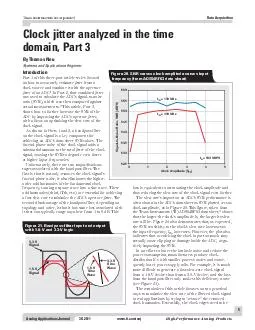
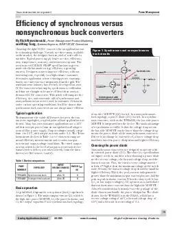
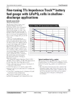


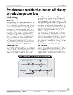
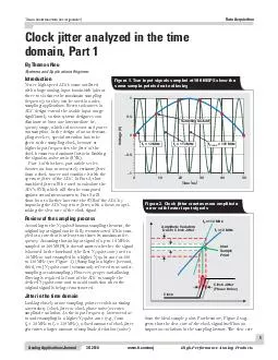
Analog Applications JournalTexas Instruments Incorporated High-Performance Analog Productswww.ti.com/aaj1Q 2009Power ManagementCell balancing buys extra run time and battery lifeCommon to every battery system with series cells is the problem of cell imbalance. Cell balancing is a method of designing safer battery solutions that extends battery run Texas Instruments Incorporated Analog Applications Journal 1Q 2009www.ti.com/aajHigh-Performance Analog ProductsPower Managementsystem (see Figure 1), comparing cell voltages with programmable thresholds to determine if cell balancing is needed. Figure 2 shows the operation principle. If any particular cell hits the threshold, charging is halted and an internal bypass is enabled. The charging is halted until the high-voltage cell hits the recovery limit, when the cell balancing will stop.Cell-balancing algorithms that use only voltage divergence as a balancing criterion have the disadvantage of overbalancing or underbalancing because of the different impedance between cells (see Figure 3). The problem is that cell impedance also contributes to voltage divergence during charging. The pack protector using simple voltage-based cell balancing cannot tell if the voltage difference is caused by the capacity or the impedance imbalance. Therefore, this type of balancing cannot guarantee that all cells will reach 100% capacity at full charge.The bq2084 is a fuel gauge with an improved version of voltage-based balancing. To minimize the effect of impedance differences between cells, the bq2084 balances only near the end of charge, where the current tapers off. In addition, the bq2084 is a more efficient implementation Regulator,Temperature, Fuse RSense5 to 10Li-lonCells Figure 1. The bq77PL900 acting as stand-alone battery protector V=CellAV–OVOVH VDiff_Start Figure 2. Simple passive cell balancing based on voltage îell Voltage and îurrent Voltage Figure 3. Simple voltage-based cell balancing may not effectively balance capacity Texas Instruments Incorporated Analog Applications Journal High-Performance Analog Productswww.ti.com/aaj1Q 2009Power Managementbecause it makes the balancing decision based on all cell voltages. Despite the improvements, this techniquelimitsthebalancingtohighaSO2regionsandcan be performed only during charging.The bq20zxx family of Impedance Track™ fuel gauges uses a different balancing strategy based on cellSO2andcapacitygInsteadofbalancingvoltagedivergence, the bq20zxx gauges calculate the charge, , that each cell needs to reach a full-charge state, then find the difference, Qtbetweenthe of each cell. The balancing algorithm turns on the cell-balancing FETs during charging to zero out QgTheImpedanceTrackfuelgaugesimplementthese tasks with ease because the total capacity, andtheSO2arereadilyavailablefromthegauging function. Furthermore, since this method of cell balancing is not compromised by cell impedance (it actually monitors cell impedance), it can be performed at any time, during charge or discharge or even at idle. More important, it achieves the best passive-balancing accuracy (see Figure 4).Active cell balancing overcomes the energy loss of the passive method by using capacitive or inductive charge storage and shuttling to deliver energy to where it is needed most, and with little loss. Thus it is preferable for efficiency-conscious designs and for applications where delivering maximum run time is top priority.The bq78PL114 PowerPump™ cell-balancing technology is TI’s latest implementation of active cell balancing using inductive charge transfer. PowerPump uses an n- and pachannelMOSFETpairandpowerinductortocompletea charge-transfer circuit between an adjacent pair of cells. MOSFETsform a buck/boost circuit. If the bq78PL114 determines that the top cell needs to transfer energy to the lower cell, the P3S signal, running at about 200 kHz with a duty cycle of 30%, triggers the energy to transfer from the top cell to theinductorthroughthetoppachannelMOSFETtQugWhenthePBSsignalresetstQuisturnedofftandtheenergystored in the inductor reaches a maximum. Because the inductor current must flow continuously, the body diode from the inductor to the lower cell. In this process, energy is stored in the inductor with only minor loss due to the the body diode.The bq78PL114 features three selectable balancing Terminal-voltage pumping is just like the voltage-based passive cell balancing described earlier.Open-circuit voltage (OCV) pumping compensates for impedancedifferencesbyestimatingthe O2basedonmeasurements of the pack current and cell impedance.SOC pumping (predictive balancing) is like the bq20zxx family’s passive cell-balancing method based capacityg rBcpyN2 1O rVoeta Figure 5. PowerPump cell balancing lîlerîreBîamdd codpyNm Ocf Figure 4. Passive cell balancing based on SOC and capacity Texas Instruments Incorporated Analog Applications Journal 1Q 2009www.ti.com/aajHigh-Performance Analog ProductsPower Managementdetermines the exact charge that needs to be transferred between cells so that cell capacities are balanced at the end of charge. This method therefore achieves the best active-balancing accuracy, as shown in Figure 6.Because of the higher balancing current, PowerPump technology corrects cell imbalance much better than conventional integrated, passive balancing with internal bypass FETs. Adjustable by changing component values, the typical effective balancing current for a notebook PC is about 25 to 50 mA, which is about 12 to 20 times better than the internal IC bypass balancing. With this strength, most typical capacity imbalances (of less than 5%) can be overcome in one or two cycles.Apart from the obvious advantages, the beauty of the PowerPump cell-balancing technology is that balancing is achievable regardless of the individual cell voltages. Balancing can happen during any battery operation—charge, discharge, or rest—and even if the cell that provides the charge has a lower voltage than the cell that receives it! Compared with passive cell balancing, little energy is lost as heat.PowerPump cell balancing is fast by nature. A 2% capacity imbalance from a 2200-mAh cell can be balanced within a charge cycle or two. However, as previously mentioned, passive cell balancing using integrated FETs is limited by low balancing current and therefore may require multiple cycles to correct a typical imbalance. The balancing may even be overpowered by the rate of cell divergence/imbalance. To improve the speed of passive cell balancing, an external bypass can be established to utilize existing hardware. A typical implementation, shown in Figure 7, can be used with the bq77PL900, the bq2084, or the bq20zxx family. The internal balancing MOSFETforparticularcellisfirstturnedontcreatinga low-level bias current through the external filter resistors, R and R, that connect the cell terminals to the IC. The gate-to-source voltage is thus established across RThe RoftheexternalMOSFETisnegligibletandtheexternal balancing current, I, is governed by cell voltage and R ExternalMOSFET IBalIBiasBalancing ICRExt1RExt2–V+GateRBal Battery+– Figure 7. Principle of external passive cell balancing ntde Figure 6. Active cell balancing with SOC-pumping algorithm Texas Instruments Incorporated Analog Applications Journal High-Performance Analog Products www.ti.com/aaj 1Q 2009Power ManagementThe drawback of this method is that balancing cannot be performed on adjacent cells at the same time (see Figure 8a). This is because, when adjacent internal FETs are turned on, there is no current flowing through R, so In practice, this is not an issue because the fast external cell balancing can quickly balance the cell associated with Another issue is the stress from the high drain-to-source voltage, V, that occurs when every other cell is balanced. In Figure 8b, the top and bottom cells are being balanced. Due to the cell-balancing bias, there is a high at the middle internal switch that may exceed what the switch can sustain. The solution to this problem is to limit the maximum value of R or exclude simultaneous balancing of every other cell.Fast cell balancing is a new way of thinking about enhancing battery safety and performance. In passive balancing, the practical goal is to achieve capacity balance at the end of charge; but, due to the low balancing current, little can be done to also correct voltage imbalance at the end of discharge. In other words, overcharging weak cells can be avoided, but it may not be possible to improve battery run time because the extra energy is wasted in the bypass resistance as heat. With fast PowerPump active balancing, the two goals—achieving capacity balance at the end of charge, and minimizing voltage differences among cells at the end of discharge—can potentially be achieved at the same time. Energy is conserved and transferred to weaker cells, which increases discharge capacity.One of the emerging technologies for enhancing battery safety and extending battery life is advanced cell balancing. Since new cell balancing technologies track the amount of balancing needed by individual cells, the usable life of battery packs is increased, and overall battery safety is enhanced. In fast PowerPump active balancing, battery run time can also be maximized by balancing at high efficiency at the end of discharge in every cycle.Related Web sitespower.ti.comwww.ti.com/sc/device/ with bq2084-V143, bq20z90, bq77PL900, or bq78PL114 V=I= –V–V BatteryCell+–BatteryCell+– Figure 8. Issues with internal-FET balancing(a) Adjacent cells cannot be balanced at the same time(b) High-VDS stress occurs when every other cell is balanced BatteryCellBattery++––Battery+–VDS–+V V IBalQ1Q2Q3IBalIBiasIBiasRBalRBalRBalBalancing ICRExtRExtRExtRExt IMPORTANT NOTICE Texas Instruments Incorporated and its subsidiaries (TI) reserve the right to make corrections, modifications, enhancements, improvements, and other changes to its products and services at any time and to discontinue any product or service without notice. Customers should obtain the latest relevant information before placing orders and should verify that such information is current and complete. All products are sold subject to TIs terms and conditions of sale supplied at the time of order acknowledgment. TI warrants performance of its hardware products to the specifications applicable at the time of sale in accordance with TI's standard warranty. Testing and other quality control techniques are used to the extent TI deems necessary to support this warranty. Except TI Worldwide Technical Support PageTI Semiconductor KnowledgeBase Home PageMexicoEurope, Middle East, and Africa The European Free Call (Toll Free) number is not active in all countries. If you have technical difficulty calling the free call number, www.tij.co.jp/pi Toll-Free Number Taiwan © 2009 Texas Instruments IncorporatedImpedance Track and PowerPump are trademarks of Texas Instruments. All other trademarks Safe Harbor Statement: This publication may contain forward-looking statements that involve a number of risks and uncertainties. These “forward-looking statements” are intended to qualify for the safe harbor from liability established by the Private Securities Litigation Reform Act of 1995. These forward-looking statements generally can be identified by phrases such as TI or its management “believes,” “expects,” “anticipates,” “foresees,” “forecasts,” “estimates” or other words or phrases of similar import. Similarly, such statements herein that describe the company's products, business strategy, outlook, objectives, plans, intentions or goals also are forward-looking statements. All such forward-looking statements are subject to certain risks and uncertainties that could cause actual results to differ materially from those in forward-looking statements. Please refer to TI's most recent Form 10-K for more information on the risks and uncertainties that could materially affect future results of operations. We disclaim any intention or obligation to update any forward-looking statements as a result of developments occurring after the date SLYT322 NOTICEInstrumentsIncorporatedanditssubsidiaries(TI)reservetherighttomakecorrections,modifications,enhancements,improvements,andotherchangestoitsproductsandservicesatanytimeandtodiscontinueanyproductorservicewithoutnotice.Customersshouldobtainthelatestrelevantinformationbeforeplacingordersandshouldverifythatsuchinformationiscurrentandcomplete.AllproductsaresoldsubjecttoTIstermsandconditionsofsalesuppliedatthetimeoforderacknowledgment.TIwarrantsperformanceofitshardwareproductstothespecificationsapplicableatthetimeofsaleinaccordancewithTIsstandardwarranty.TestingandotherqualitycontroltechniquesareusedtotheextentTIdeemsnecessarytosupportthiswarranty.Exceptwheremandatedbygovernmentrequirements,testingofallparametersofeachproductisnotnecessarilyperformed.TIassumesnoliabilityforapplicationsassistanceorcustomerproductdesign.CustomersareresponsiblefortheirproductsandapplicationsusingTIcomponents.Tominimizetherisksassociatedwithcustomerproductsandapplications,customersshouldprovideadequatedesignandoperatingsafeguards.TIdoesnotwarrantorrepresentthatanylicense,eitherexpressorimplied,isgrantedunderanyTIpatentright,copyright,maskworkright,orotherTIintellectualpropertyrightrelatingtoanycombination,machine,orprocessinwhichTIproductsorservicesareused.InformationpublishedbyTIregardingthird-partyproductsorservicesdoesnotconstitutealicensefromTItousesuchproductsorservicesorawarrantyorendorsementthereof.Useofsuchinformationmayrequirealicensefromathirdpartyunderthepatentsorotherintellectualpropertyofthethirdparty,oralicensefromTIunderthepatentsorotherintellectualpropertyofTI.ReproductionofTIinformationinTIdatabooksordatasheetsispermissibleonlyifreproductioniswithoutalterationandisaccompaniedbyallassociatedwarranties,conditions,limitations,andnotices.Reproductionofthisinformationwithalterationisanunfairanddeceptivebusinesspractice.TIisnotresponsibleorliableforsuchaltereddocumentation.Informationofthirdpartiesmaybesubjecttoadditionalrestrictions.ResaleofTIproductsorserviceswithstatementsdifferentfromorbeyondtheparametersstatedbyTIforthatproductorservicevoidsallexpressandanyimpliedwarrantiesfortheassociatedTIproductorserviceandisanunfairanddeceptivebusinesspractice.TIisnotresponsibleorliableforanysuchstatements.TIproductsarenotauthorizedforuseinsafety-criticalapplications(suchaslifesupport)whereafailureoftheTIproductwouldreasonablybeexpectedtocauseseverepersonalinjuryordeath,unlessofficersofthepartieshaveexecutedanagreementspecificallygoverningsuchuse.Buyersrepresentthattheyhaveallnecessaryexpertiseinthesafetyandregulatoryramificationsoftheirapplications,andacknowledgeandagreethattheyaresolelyresponsibleforalllegal,regulatoryandsafety-relatedrequirementsconcerningtheirproductsandanyuseofTIproductsinsuchsafety-criticalapplications,notwithstandinganyapplications-relatedinformationorsupportthatmaybeprovidedbyTI.Further,BuyersmustfullyindemnifyTIanditsrepresentativesagainstanydamagesarisingoutoftheuseofTIproductsinsuchsafety-criticalapplications.TIproductsareneitherdesignednorintendedforuseinmilitary/aerospaceapplicationsorenvironmentsunlesstheTIproductsarespecificallydesignatedbyTIasmilitary-gradeor"enhancedplastic."OnlyproductsdesignatedbyTIasmilitary-grademeetmilitaryspecifications.BuyersacknowledgeandagreethatanysuchuseofTIproductswhichTIhasnotdesignatedasmilitary-gradeissolelyattheBuyer'srisk,andthattheyaresolelyresponsibleforcompliancewithalllegalandregulatoryrequirementsinconnectionwithsuchuse.TIproductsareneitherdesignednorintendedforuseinautomotiveapplicationsorenvironmentsunlessthespecificTIproductsaredesignatedbyTIascompliantwithISO/TS16949requirements.Buyersacknowledgeandagreethat,iftheyuseanynon-designatedproductsinautomotiveapplications,TIwillnotberesponsibleforanyfailuretomeetsuchrequirements.FollowingareURLswhereyoucanobtaininformationonotherTexasInstrumentsproductsandapplicationsolutions:ProductsApplicationsAmplifiersamplifier.ti.com www.ti.com/audio Convertersdataconverter.ti.com www.ti.com/automotive ®Productswww.dlp.com www.ti.com/broadband dsp.ti.com Controlwww.ti.com/digitalcontrol andTimerswww.ti.com/clocks www.ti.com/medical interface.ti.com www.ti.com/military logic.ti.com Networkingwww.ti.com/opticalnetwork Mgmtpower.ti.com www.ti.com/security microcontroller.ti.com www.ti.com/telephony www.ti-rfid.com &Imagingwww.ti.com/video andZigBee®Solutionswww.ti.com/lprf www.ti.com/wireless Address:TexasInstruments,PostOfficeBox655303,Dallas,Texas75265Copyright©2009,TexasInstrumentsIncorporated