
The tension members can have a variety of cross sections The single angle and double angle sections Fig 2 a are used in light roof trusses as in industrial buildings The tension members in bridge trusses are made of channels or I sections acting individually or builtup Figs 2 ID: 1015727
Download Presentation The PPT/PDF document "Tension members Choice of Section" is the property of its rightful owner. Permission is granted to download and print the materials on this web site for personal, non-commercial use only, and to display it on your personal computer provided you do not modify the materials and that you retain all copyright notices contained in the materials. By downloading content from our website, you accept the terms of this agreement.


1. Tension members
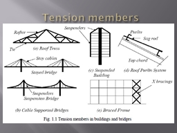
2. Choice of SectionThe tension members can have a variety of cross sections. The single angle and double angle sections [Fig 2(a)] are used in light roof trusses as in industrial buildings. The tension members in bridge trusses are made of channels or I sections, acting individually or built-up [Figs. 2(c) and 2(d)]. The circular rods [Fig.2 (d)] are used in bracings designed to resist loads in tension only. They buckle at very low compression and are not considered effective. Steel wire ropes [Fig.2 (e)] are used as suspenders in the cable suspended bridges and as main stays in the cable-stayed bridges.
3. Cross Sections
4.
5.
6.
7.
8.
9.
10.
11.
12.
13.
14.
15.
16.
17.
18.
19.
20.
21.
22. NET SECTION FRACTURE
23. FAILURE AT GUSSET
24.
25. Block shear failure
26.
27.
28.
29.
30. (a) At end of member (b) In gusset plates
31. EXAMPLES OF BLOCK SHEAR FAILURE Examples of Block Shear (between two gussets)
32. EXAMPLES OF BLOCK SHEAR FAILURE Strength as governed by Block Shear Failure(Case – 1)(Case – 2)
33. SECOND SET
34. IntroductionApplicationsTension Members in BuildingsTieRafterRoof TrussSuspendersSuspended BuildingPurlinSag RodTop chordRoof Purlin SystemBracingsBraced Frame
35. Introduction…Cross Sections usedSingle & Double AnglesChannelI-Section(Joist / Beam)RodCableBuilt-up Sections
36. Introduction…Material0E = 200 GPaMild Steel0.00125fy = 2500.012≈ 0.0150.23 – 0.25High Strength Steelfy0.2%fufuCommon SteelsεσLarge elongationSmall elongationfy / fu ≈ 0.6 – 0.85
37. Section Design in Tension
38. Behaviour in TensionPlate0fy fuεσf2 possible Limit States Yielding Ultimate (Rupture)Important: Yielding of Gross Area
39. Behaviour in Tension…Plate with Hole0fy fuεσ2 possible Limit States Yielding Ultimate (Rupture)fElasticfyElasto-PlasticfuPlasticImportant: Rupture of Net Area
40. Design Strategy for TensionGross Area Design Strength Tdg Tdg = fy Ag / gm0 (gm0 = 1.15)Ag = Gross cross-sectional areaNet Area Design Strength Tdn Tdn = fu An / gm1 (gm1 = 1.25)0.9 factor:: Statistical evaluation of test dataAn = Net area ??fuPlastic 0.9
41. Net Area…Plate with Multiple HolesAll possible failure paths to be investigatedMinimum net area to be used in design Tensile strengthdbAn = [b – nd + (p2/4g)] ttgpggppp2/4g for all inclined parts of the section
42. Net Area…Three types of Bolt Holes (Table 19, pp 73) Standard clearance holeOver size holeSlotted holeShortLongStandard(STD)Oversized(OVS)Short-slotted(SSL)Long-slotted(LSL)1820182256Different holes for 16mm (nominal) diameter bolt
43. Net Area…Punctured Bolt Holes (Cl 3.6.1, pp 17) 2 mm excess of actual diameterAll possible failure paths to be investigatedMinimum net area to be used in design dbAn = [b – nd + (p2/4g)] ttgpggppp2/4g for all inclined parts of the section
44. Design Strategy for TensionGross Area Design Strength Tdg Tdg = fy Ag / gm0 (gm0 = 1.15)Ag = Gross cross-sectional areaNet Area Design Strength Tdn Tdn = 0.9 fu An / gm1 (gm1 = 1.25)An = Net area
45. Block ShearPlatesMore than one bolt lineBolt shear strength and plate bearing strength are higher1243Shear PlanesTension PlaneCourtesy:: Georgia Inst Tech
46. Rupture in Tension (Atn)Yield in Shear (Avg)Design Strategy for Block ShearGross and Net Areas in Tension & ShearRupture in Tension (Atn)Rupture in Shear (Avn)Yield in Tension (Atg)Yield in Shear (Avg)Yield in Tension (Atg)Rupture in Shear (Avn)
47. Interaction of Normal stress (Tensile) & Shear stressvon Mises yield criterionDesign Shear Strength at YieldDesign Strategy for Block Shear…xyz
48. Design Strategy for Block Shear…Block Shear Design Strength Tdb is smaller of Avg (fy / √3) / gm0 + 0.9 Atn fu / gm1 0.9 Avn (fu / √3) / gm1 + Atg fy / gm0AssumptionWhen one (either) plane reaches ultimate strength, the other plane develops full yieldYield of Gross area in shearRupture of Net area in tensionRupture of Net area in shearYield of Gross area in tension++or
49. Non-Uniform StressMore stress near restraintLess stress near un-restrained / free endsT / AgT/2T/2
50. Shear LagChannelsBoth legs connectedGusset PlatePart of cross-section NOT effectiveLess Stressed
51. Shear Lag…AnglesSingle leg connectedEccentrically loaded through gusset platesFree, Un-stiffened,Un-connected endGusset PlatePart of cross-section NOT effectiveLess Stressed
52.
53. Shear Lag…Effects of Shear LagStrength reductionPart of cross-section ineffective (less stressed)Consider in DesignFactors affecting / causing Shear LagOutstand (unconnected part)More outstand – more shear lagThin / slender outstand – more shear lagConnection stiffnessFlexible connection – more shear lagSingle leg connection versus both leg connectionOne bolt versus multiple bolt connection
54. Angles in TensionDesign StrategyYielding of gross sectionRupture of net sectionBlock shear
55. Angles in Tension…Rupture of net section Tdn = 0.9 × Anc × fu / gm1 + b × Ago × fy / gm0Anc = Net area of the connected legAgo = Gross area of the unconnected leg b = reduction factor based on contribution of unconnected outstand
56. Angles in Tension…Rupture of net section Tdn = 0.9 × Anc × fu / gm1 + b × Ago × fy / gm0www1ttbs = w + w1 - tbs = w
57. Angles in Tension…Rupture of net sectionLimits of (b × Ago × fy / gm0)Upper limit: Ago × fu / gm1Full unconnected length ruptureLower limit: 0.7 × Ago × fy / gm070% of unconnected length yielding
58. Angles in Tension…Rupture of net section Tdn = a × An × fu / gm1Approximate EstimateCaseaOne or two bolts0.6Three bolts0.7Four or more bolts0.8Weld0.8
59. Angles in Tension…Block Shear1243Shear PlaneTension Plane
60. Welded Tension MembersNo “Net” AreaNo reduction of area due to bolt holesDesign strength based on Gross Area only
61. fuThreaded Rods in TensionDesign StrategyYielding of gross sectionAg × fy / gm0Rupture of net section0.9 × An × fu / gm1d grossd rootfyElasto-PlasticPlasticElasticf ≤ fyCourtesy:: AISC
62. Member Design in Tension
63. Stiffness RequirementsCaseMaximum l/r limitPretensioned Members (always in tension)No LimitMembers under tension only(not always in tension!)400Not designed for compression under stress reversal (may also be in some compression!!)350Designed for compression under stress reversal (will also be in compression)250
64. Stiffness Requirements…Serviceability Limit StateTo controlDeflectionVibrationTo facilitateEase of handlingTransportation and erection requirementsMinimization of damage during fabricationDo Not affect “Strength” of the member
65. Design StepsFactored Design Force Demand TCalculate Ag req = T / (fy / gm0)An req = T / (fu / gm1)Choose a trial sectionAnalyse for its strength TdEnsure Td > T (Capacity > Demand)Check l/r to be within prescribed limitsEfficiency h = T / (Ag × fy / gm0)
66. Design Steps…Efficiency h = T / (Ag × fy / gm0)100% EfficiencyGross Area YieldingWelded connectionBolted ConnectionEfficiency may reduce due toBolt holesNet area rupture governingShear lagBlock shear
67. SummaryTension MembersEfficient load carrying membersEfficiency may reduce due toBolt holesShear lagBlock shear
68. IS 800: 2007Section 6 (page 32 – 33)6.1 Tension Members6.2 Design Strength due to Yielding of Gross Section6.3 Design Strength due to Rupture of Critical Section6.4 Design Strength due to Block Shear
69. THIRD SET
70.
71. Step 1 Obtain Gross AREA OF tension member Assuming that section has failed in yielding
72.
73.
74.
75.
76.
77.
78.
79. Type of connection FailuresShearing Failure of Bolts.Bearing Failure of plate.Tearing failure at edge of plate.79
80. Failure of bolted joint
81.
82. Failure of bolted joint
83. Type of connection Failures83Shearing failure of bolts
84. Type of connection Failures84Shearing failure of bolts
85. 85Bearing Failure of PlateType of connection Failures
86. Shear & Bearing Area86Type of connection Failures
87. ANALYSIS AND DESIGN PROBLEMS ON TENSION MEMBERS
88.
89. 1
90. 2
91.
92.
93. 3
94.
95. Design a double angle section to carry a tension of 300kN. The end connection is to be made using M20 bolts of product g grade C and property class 5.6. Assume the angles as provided on both sides of gusset plate. The yield and ultimate strength of steel are 150 MPa and 410 MPa respectively.HOME ASSIGNMENT