
a Synthesized Parallel Multiplier Sungmin Bae HyungOck Kim Jungyun Choi and Jaehong Park Design Technology Infrastructure Design Center SystemLSI Business Division Warning This document is intended only for the recipients designated by Samsung Electronics Co Ltd Samsu ID: 241050
Download Presentation The PPT/PDF document "Coarse-grained Structural Placement for" is the property of its rightful owner. Permission is granted to download and print the materials on this web site for personal, non-commercial use only, and to display it on your personal computer provided you do not modify the materials and that you retain all copyright notices contained in the materials. By downloading content from our website, you accept the terms of this agreement.


Slide1
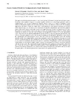
Coarse-grained Structural Placement for a Synthesized Parallel Multiplier
Sungmin Bae, Hyung-Ock Kim, Jungyun Choi, and Jaehong ParkDesign TechnologyInfrastructure Design CenterSystem-LSI Business Division
Warning
This document is intended only for the recipients designated by Samsung Electronics Co. Ltd. (“Samsung”). As it contains the trade secrets and confidential information of Samsung which are protected by Competition Law, Trade Secrets Protection Act and other related laws, this document may not be, in part or in whole, directly or indirectly publicized, distributed, photocopied or used (including in a posting on the Internet where unspecified individuals may access it) by any unauthorized third party. Samsung reserves its right to take legal measures and claim damages against any party that misappropriates Samsung’s trade secrets or confidential information.Slide2
Outline
MotivationDesign flowParallel multiplierCoarse-grained structural placement methodologyExperimental resultsFuture worksSlide3
Motivation
Data-flow (design structure) awareness is crucial to enhance physical design qualities.Timing, area, congestion, and power etc.Structured datapath placement is mostly done manually.It is generally thought that placement tools do not perform well on the datapath designs.Design efforts; days ~ weeks3FloorplanMemory macro placementStructured datapath placementCoarserFinerControl granularity
Sum = A + B
Floorplan
Memory macro placement
Structured datapath placement
Coarser
Finer
Control granularitySlide4
MotivationWe have added another methodology in the data-flow aware physical
design.Automated extracting and mapping for a synthesized parallel multiplier to guide structural placement of a global placement.4Sum = A * BFloorplanMemory macro placementCoarse-grained structured datapath placementCoarser
Finer
Control granularity
Structured datapath placement
Logic Synthesis
Automated
datapath
e
xtraction and mapping
Datapath
template
Floorplan
Memory macro placement
Structured datapath placement
Coarser
Finer
Control granularitySlide5
Design Flow
Identify cells of a synthesized parallel multiplier to be structurally placedInherent structural location extractions of the cellsAnalyze data-flow of the multiplierStructurally mapping the cells on a logical 2-D arrayPhysical bit-slice alignment of the cellsGenerate structural relative placement directivesGuide structural placement during global placement5
Technology independent
and dependent optimizations
RTL code
Datapath generator
Logic Synthesis
Physical aware bit-slice alignment
Optimized
gate-level netlist
Structural templates (Multiplier)
Parsing/Elaboration
Arithmetic
operation extraction
High-level arithmetic optimizations
Non-arithmetic logic
Dataflow analysis
High-level optimizations
Result satisfactory?
Structure Extraction and Mapping
User
Technology
library
Timing/
Area constraints
Structural location inference/
Cell mapping
No
No
Yes
Coarse-grained structural placement
Structural relative placement directives
Global PlacementSlide6
Parallel Multipliers
A parallel multiplier is one of the most abundant arithmetic circuits in today’s multi-media feature intensive SoCs. Parallel multiplier largely consists of three parts.Partial product generationPartial product reductionCarry propagating adder (Final adder)6
Multiplicand
Multiplier
Partial Products
Final Product
Partial Product
Partial Product
Reduction
Multiplicand
Multiplier
Final Adder
Final Product
Multiplication in dot-notation
X3Y3
X3Y2
X3Y1
X3Y0
X2Y3
X2Y2
X2Y1
X2Y0
X1Y3
X1Y2
X1Y1
X1Y0
X0Y3
X0Y2
X0Y1
X0Y0
S3
S2
S1
S
0
S7
S6
S5
S4
X3
X2
X1
X0
Y3
Y2
Y1
Y0Slide7
Parallel Multipliers
Partial product generationNon-booth : it generates the logical product of a multiplicand and multiplier (AND).Booth (Radix-4) : it reduces the number of partial products to the half.Partial product reductionCarry-save adder tree: it reduces every column to 2 output rows using compressor cell.Carry-propagate adder (final adder)Carry look ahead adder : it adds the 2 output rowsYj
X
i
PP
ij
Booth
Non-booth
Partial product generation
3:2
3:2
PP
i-1j+1
PP
ij
PP
i+1j-1
C
in
C
out
Sum
PP
i+2j-2
Partial product reduction
Carry-look ahead unit
FA
FA
FA
A2 B2
A1 B1
A0 B0
S2
S1
S0
C2
C1
C0
C3
P2 G2
P1 G1
P0 G0
Carry-propagate adder
Multiplicand
Multiplier
Partial Products
Final Product
Partial Product
Partial Product
Reduction
Multiplicand
Multiplier
Final Adder
Final Product
Multiplication in dot-notationSlide8
Design Flow
It performsIdentify cells of a synthesized parallel multiplier to be structurally placedThe PI cells from the partial product generationThe PO cells from the final adderInherent structural location extraction of the cellsTagging structural locations for the PI and PO cells Analyze data-flow of the multiplierStructurally mapping the cells on a logical 2-D arrayPhysical bit-slice alignment of the cellsGenerate structural relative placement directivesGuide structural placement during global placement8
Technology independent
and dependent optimizations
RTL code
Datapath generator
Logic Synthesis
Physical aware bit-slice alignment
Optimized
gate-level netlist
Structural templates (Multiplier)
Parsing/Elaboration
Arithmetic
operation extraction
High-level arithmetic optimizations
Non-arithmetic logic
Dataflow analysis
High-level optimizations
Result satisfactory?
Structure Extraction and Mapping
User
Technology
library
Timing/
Area constraints
Structural location inference/
Cell mapping
No
No
Yes
Coarse-grained structural placement
Structural relative placement directives
Global PlacementSlide9
PI Cell Structural Location Inference
The PI cells from the partial product generationThe PI cells are retrieved by the immediate fan-out cone cells of the input nets.A set of nets that to collect the PI cells differs depending on the type of the partial product generation.Non-booth : multiplicand and multiplier input netsBooth : multiplicand input nets9Yj
X
i
PP
ij
Booth
Non-booth
Partial product generation
Partial Product
Partial Product
Reduction
Multiplicand
Multiplier
Final Adder
Final Product
X3Y3
X3Y2
X3Y1
X3Y0
X2Y3
X2Y2
X2Y1
X2Y0
X1Y3
X1Y2
X1Y1
X1Y0
X0Y3
X0Y2
X0Y1
X0Y0
S3
S2
S1
S
0
S7
S6
S5
S4
X3
X2
X1
X0
Y3
Y2
Y1
Y0Slide10
After extracting the PI cells, the PI cells are tagged by 2-D locations
of a partial product row and column.Row inferenceColumn inferenceThe row of the PI cell can be inferred by its topologically closest multiplier inputs.Row inference i indicates the ith row of the partial product generator.PIrow(Ck) : the row number of the PI cell CkPIcol(Ck) : the column number of the PI cell CkBmd(Ck) : the closest multiplicand bit of CkBmr(Ck) : the closest multiplier bit of CkPPtype : the partial product typePI Cell Structural Location Inference
Y
j
X
i
PP
ij
Booth
Non-boothSlide11
PI Cell Structural Location Inference
The column of the PI cell can be inferred by its topologically closest and bit-slice aligned multiplier output bit.Topological order propagation is restricted to only follow the same weighted bit-slice along the CSA tree.Ignoring carry-out pins of the compressor cells.Column inference Find topologically closest and bit-slice aligned result. 113:2
3:2
3:2
3:2
3:2
3:2
3:2
Column[i+1]
Column[i]
X3Y3
X3Y2
X3Y1
X3Y0
X2Y3
X2Y2
X2Y1
X2Y0
X1Y3
X1Y2
X1Y1
X1Y0
X0Y3
X0Y2
X0Y1
X0Y0
S3
S2
S1
S
0
S7
S6
S5
S4
X3
X2
X1
X0
Y3
Y2
Y1
Y0Slide12
PO Cell Extraction
The PO cells are parts of the final carry propagating adder.The PO cells are retrieved by the immediate fan-in cone cells of the output nets.Tags corresponding multiplier output bits to the PO cells12Carry-look ahead unitFAFAFA
A2 B2
A1 B1
A0 B0
S2
S1
S0
C2
C1
C0
C3
P2 G2
P1 G1
P0 G0
Carry-propagate adder
Partial Product
Partial Product
Reduction
Multiplicand
Multiplier
Final Adder
Final ProductSlide13
Design Flow
It performsIdentify cells of a parallel multiplier to be structurally placedInherent structural location extraction of the cellsStructurally mapping the cells on a logical 2-D arrayAnalyze data-flow of the multiplierPhysical bit-slice alignment of the cellsGenerate structural relative placement directivesGuide structural placement during global placement13
Technology independent
and dependent optimizations
RTL code
Datapath generator
Logic Synthesis
Physical aware bit-slice alignment
Optimized
gate-level netlist
Structural templates (Multiplier)
Parsing/Elaboration
Arithmetic
operation extraction
High-level arithmetic optimizations
Non-arithmetic logic
Dataflow analysis
High-level optimizations
Result satisfactory?
Structure Extraction and Mapping
User
Technology
library
Timing/
Area constraints
Structural location inference/
Cell mapping
No
No
Yes
Coarse-grained structural placement
Structural relative placement directives
Global PlacementSlide14
Design Flow
Data-flow can be analyzed from a global placementData-flow can be estimated by relative locations of the input and output related cells.A method for the data-flow analysis …Linear regression to get the lines of the input and output related cells. Analyze the input to output lines’ relation14any overlap between the lines? angle of the overlap etc.
Top to bottom or left to right etc. ?
MSB to LSB or LSB to MSB?
?
?Slide15
Design Flow
It performsIdentify cells of a parallel multiplier to be structurally placedInherent structural location extraction of the cellsAnalyze data-flow of the multiplierStructurally mapping the cells on a logical 2-D arrayUsing the inferred row and column numbers.Physical bit-slice alignment of the cellsGenerate structural relative placement directivesGuide structural placement during global placement
Technology independent
and dependent optimizations
RTL code
Datapath generator
Logic Synthesis
Physical aware bit-slice alignment
Optimized
gate-level netlist
Structural templates (Multiplier)
Parsing/Elaboration
Arithmetic
operation extraction
High-level arithmetic optimizations
Non-arithmetic logic
Dataflow analysis
High-level optimizations
Result satisfactory?
Structure Extraction and Mapping
User
Technology
library
Timing/
Area constraints
Structural location inference/
Cell mapping
No
No
Yes
Coarse-grained structural placement
Structural relative placement directives
Global PlacementSlide16
Structural Cell Mapping
The PI cells are mapped onto a logical 2-D array according to their tagged row and column numbers.However, the number of cells inferring to the same location can be uneven due to the local nature of logic synthesis optimizations.If enough slots are allocated for all the cells, the 2-D array may have uncontrollable aspect ratio which may degrade placement quality.The maximum number of columns is constrained to control the array dimension.The number of rows is fixed.Some mis-mappings are allowed.Slot sharing between adjacent columns.There are spacing between the rows of the 2-D array.Non-guided cells to be placed close to their inherent structural locations.16Slide17
Structural Cell Mapping
Min-cost max-flow based cell mapping to maximize the number of mapped PI cells with minimum mis-mapping cost for a given 2-D array.An initial 2-D slot array may not fully contain all the PI cells.It allows empty slot sharing between adjacent bit-slice columns.It iteratively add dummy (empty) column slots at columns with the worst mis-mapping costs during the mapping.17
Column[i]
PI Cell[i,0]
Cost [0,0]
Cost [0,1]
Cost [0,n]
m
slots
Column[i-1]
Column[i+1]
PI Cell[i-1,0]
PI Cell[i+1,0]
Capacity = m
Capacity = m
Capacity = m
Dummy Slot[i]
k
slots
Cost [0,0]
Cost
SH
[0,0]
Cost
DS
[0,0]
Capacity = j
j slots
Shared Slot
Capacity = k
Cost
SH
[0,0]
Cost
DS
[0,0]
The
slots
are divided into the three
types for each column having different mapping cost weights.
Non-shared
: mapping weight
γ
own
Shared
: mapping weight
γ
shared
Dummy
: mapping weight
γ
dummy
Mis-mapping
cost :
γ
x
*|row
cell
– row
slot
|
Column[i]
PI Cell[i,0]
Cost [0,0]
Cost [0,1]
Cost [0,n]
m
slots
Column[i-1]
Column[i+1]
PI Cell[i-1,0]
PI Cell[i+1,0]
Capacity = m
Capacity = m
Capacity = m
Cost [0,0]
Cost
SH
[0,0]
Cost
DS
[0,0]
Capacity = j
j slots
Shared Slot
Cost
SH
[0,0]
Cost
DS
[0,0]
Shared SlotSlide18
Structural Cell Mapping
HPWL is considered to compensate for net-connection blindness of the mapping as a tiebreaker for the mapping.Linear programming formulations of the weighted sum of min-cost max-flow for CostMA(ci) and HPWL minimization for CostHPWL(ni) CostMA(ci) : weighted sum of mis-mapping cost of cell ciCostHPWL(ni) : weighted sum of mis-mapping cost of cell ciGradually add dummy column slots to minimize mis-mapping cost at columns with the worst mis-mapping cost, then solve the linear program iteratively.18Slide19
Design Flow
It performsIdentify cells of a parallel multiplier to be structurally placedInherent structural location extraction of the cellsAnalyze data-flow of the multiplierStructurally mapping the cells on a logical 2-D arrayPhysical bit-slice alignment of the cellsGenerate structural relative placement directivesGuide structural placement during global placement
Technology independent
and dependent optimizations
RTL code
Datapath generator
Logic Synthesis
Physical aware bit-slice alignment
Optimized
gate-level netlist
Structural templates (Multiplier)
Parsing/Elaboration
Arithmetic
operation extraction
High-level arithmetic optimizations
Non-arithmetic logic
Dataflow analysis
High-level optimizations
Result satisfactory?
Structure Extraction and Mapping
User
Technology
library
Timing/
Area constraints
Structural location inference/
Cell mapping
No
No
Yes
Coarse-grained structural placement
Structural relative placement directives
Global PlacementSlide20
Bit-slice Alignment
The logically mapped PI and PO cells are then bit-slice aligned with respect to their physical dimension.Strict bit-slice alignment : a column width is decided by the widest cell among themuncontrollable cell alignment sizeCompression alignment : this generates a compact cell clusterIt cannot ensure vertical bit-slice alignment20Ci,j+2
C
i-1,j+2
C
i-2,j+2
C
i,j+3
C
i-1,j+3
C
i-2,j+3
C
i,j
C
i,j+1
C
i-1,j
C
i-1,j+1
C
i,j-1
C
i-2,j
C
i-2,j+1
i-1,j-1
i-2,j-1
C
i,j+2
C
i-1,j+2
C
i-2,j+2
C
i,j+3
C
i-1,j+3
C
i-2,j+3
C
i,j
C
i,j+1
C
i-1,j
C
i-1,j+1
C
i,j-1
C
i-2,j
C
i-2,j+1Slide21
Bit-slice Alignment
Our method combines the advantages of the aforementioned methods.Align the columns within a maximum width constraintIt performs bit slice misalignment minimization while ensuring a maximum alignment width.21Ci,j+2
C
i-1,j+2
C
i-2,j+2
C
i,j+3
C
i-1,j+3
C
i-2,j+3
C
i,j
C
i,j+1
C
i-1,j
C
i-1,j+1
C
i,j-1
C
i-2,j
C
i-2,j+1
i-1,j-1
i-2,j-1
Maximum width constraint
Misalignment at each columnSlide22
Design Flow
It performsIdentify cells of a parallel multiplier to be structurally placedInherent structural location extraction of the cellsAnalyze data-flow of the multiplierStructurally mapping the cells on a logical 2-D arrayPhysical bit-slice alignment of the cellsGenerate structural relative placement directivesThe relative row and column locations of the cells The column spaces between the cellsGuide structural placement during global placement
Technology independent
and dependent optimizations
RTL code
Datapath generator
Logic Synthesis
Physical aware bit-slice alignment
Optimized
gate-level netlist
Structural templates (Multiplier)
Parsing/Elaboration
Arithmetic
operation extraction
High-level arithmetic optimizations
Non-arithmetic logic
Dataflow analysis
High-level optimizations
Result satisfactory?
Structure Extraction and Mapping
User
Technology
library
Timing/
Area constraints
Structural location inference/
Cell mapping
No
No
Yes
Coarse-grained structural placement
Structural relative placement directives
Global PlacementSlide23
Structural Relative Placement Directives Generation
After the bit-slice alignment, the structural locations and the cell spacings are transformed into structural relative placement directives.Relative row and column locations of the cellsCell spaces between the cellsTo accommodate the cell spaces, the number of the array column is set to be twice of the logical 2-D array.The compression based alignment is used to align the cell.An estimated dataflow direction is used to set the initial orientations of the arrays for global placement.23Ci,j+2
C
i-1,j+2
C
i-2,j+2
C
i,j+3
C
i-1,j+3
C
i-2,j+3
C
i,j
C
i,j+1
C
i-1,j
C
i-1,j+1
C
i,j-1
C
i-2,j
C
i-2,j+1
Cell spacing
Cell slots
Space slotsSlide24
Design Flow
It performsIdentify cells of a parallel multiplier to be structurally placedInherent structural location extraction of the cellsAnalyze data-flow of the multiplierStructurally mapping the cells on a logical 2-D arrayPhysical bit-slice alignment of the cellsGenerate structural relative placement directivesGuide structural placement during global placement
Technology independent
and dependent optimizations
RTL code
Datapath generator
Logic Synthesis
Physical aware bit-slice alignment
Optimized
gate-level netlist
Structural templates (Multiplier)
Parsing/Elaboration
Arithmetic
operation extraction
High-level arithmetic optimizations
Non-arithmetic logic
Dataflow analysis
High-level optimizations
Result satisfactory?
Structure Extraction and Mapping
User
Technology
library
Timing/
Area constraints
Structural location inference/
Cell mapping
No
No
Yes
Coarse-grained structural placement
Structural relative placement directives
Global PlacementSlide25
Structurally Guided Global Placement
Structural relative placement directives hold the locations of the PI and PO cells.Non-guided cells are attracted to the PI and PO cells.2513*12 non-Booth multiplier32*16 Booth multiplierSlide26
Experimental Results
We implemented the proposed methodology in Tcl and CLP as a linear program solver.Commercial logic synthesis and P&R tools with industrial designs were used.About 2%, 42%, and 2% improvements in critical path delay, total negative slack, and total wire-length respectively.D11 degraded the physical implementation quality, which had about 25% of the inputs are pruned due to constant propagation, and was not sufficient for the approach.26Design# MultsArea ratioCPD TNSWirelengthD170.490.940.020.99D280.171.000.82
0.98
D3
6
0.33
1.00
0.74
0.95
D4
4
0.32
0.97
0.00
0.98
D5
3
0.30
0.99
0.97
1.00
D6
1
0.25
0.98
0.91
0.95D79
0.210.980.280.94
D82
0.210.99
0.82
0.99
D9
8
0.18
0.99
0.58
1.00
D10
16
0.09
0.96
0.14
0.99
D11
1
0.40
1.03
1.10
1.02
Ave.
6
0.27
0.98
0.58
0.98Slide27
Experimental ResultsA snapshot of D10
27Slide28
Experimental ResultsTo further automate the
method, surrounding (placement blockage, macro, and data-flow etc.) awareness is needed.The multipliers were required to be “naturally” placed in a narrow macro channel, while structural placement method may prevent this kind of placement.28Slide29
Future Works
The future works will focus onExtending the methodology for other synthesized datapath circuits.Developing regularity measuring methods to avoid structurally mapping insufficiently regular multipliers.Adding more surround awareness to further automate the methodology.29Slide30