

Overview Enroute Charts Symbols Routing Preferred IFR Routes TEC Routes Facilities VOR Service Volume Obstacle Clearance Areas Operations in Other Countries Mandatory Reports Other Clearance Types ID: 719387
Download Presentation The PPT/PDF document "Enroute Charts and Procedures" is the property of its rightful owner. Permission is granted to download and print the materials on this web site for personal, non-commercial use only, and to display it on your personal computer provided you do not modify the materials and that you retain all copyright notices contained in the materials. By downloading content from our website, you accept the terms of this agreement.


Slide1
Enroute Charts and ProceduresSlide2
Overview
Enroute ChartsSymbolsRoutingPreferred IFR Routes
TEC RoutesFacilitiesVOR Service VolumeObstacle Clearance AreasOperations in Other CountriesMandatory ReportsOther Clearance Types
© 2015 Coast Flight Training. All Rights Reserved.Slide3
Enroute Navigation
91.181 is the basis for the course to be flownMust fly the center of a federal airway or direct course between nav aids or fixes
May maneuver in VFRThree strata:Lower – Base of Controlled to 18,000 feet MSLMiddle – Identifiable jet routes – FL180 to FL450Above – FL450+ is intended for random point-to-point navigation
© 2015 Coast Flight Training. All Rights Reserved.
IPG 3-1Slide4
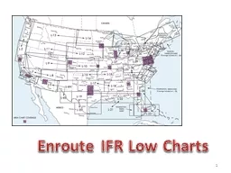
Enroute Charts
Two different charts to be used depending upon your altitude:Low Altitude Enroute Chartsaka L-Charts
17,999 MSL and belowAirways are called “Victor Airways”High Altitude Enroute ChartsFL180 to FL450Airways are called Jet Routes
© 2015 Coast Flight Training. All Rights Reserved.
JIC
5
-3Slide5
L-Charts
We will mainly talk about L-Charts because most instrument training will happen in these altitudesHigh altitude charts have similar symbols, with slight changesThe front panel shows the area the chart entails
© 2015 Coast Flight Training. All Rights Reserved.
JIC
5
-3Slide6
Navigational Aids
VOR Symbol is a small compass rose, which points to Magnetic NorthYou’ll notice the symbols are roughly the same as for SectionalsNDBs are roughly same as well
© 2015 Coast Flight Training. All Rights Reserved.
JIC
5
-5Slide7
Navigational Aids
Fixes are labeled with 5 letters and given a triangleILS Localizer symbols indicate that a fix can be identified with a LocalizerNavigation Facility Information is given in a Box, roughly the same as a Sectional
© 2015 Coast Flight Training. All Rights Reserved.
JIC
5
-5Slide8
DME and Radials
DME information is given with a number inside a D shapeDistance between fixes is a number between the respective fixesRadials are given in 3 number increments (e.g., 072, or 311)
© 2015 Coast Flight Training. All Rights Reserved.
JIC
5
-7Slide9
Airports
Can be either Brown, Blue or GreenGreen if Civilian with approachBlue if Military with approachBrown if Civilian with no approach
© 2015 Coast Flight Training. All Rights Reserved.
JIC
5
-16Slide10
Airspace
Bravo is depicted by a large blue area
© 2015 Coast Flight Training. All Rights Reserved.
JIC
5
-16Slide11
Airspace
Charlie is depicted by a large blue area with dashed lines
© 2015 Coast Flight Training. All Rights Reserved.
JIC
5
-16Slide12
Airspace
Delta is depicted by a large blue area with a D in a box after the airport identifier
© 2015 Coast Flight Training. All Rights Reserved.
JIC
5
-16Slide13
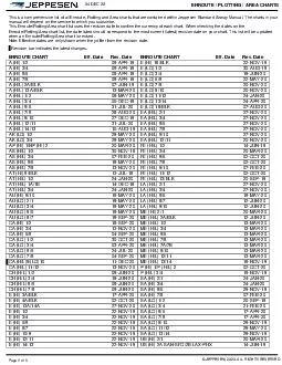
Area Charts
It may be necessary to have a large scale map of a heavily used terminal areaThese charts ease the transition from an L-Chart to the approachWill be depicted by green dashes
© 2015 Coast Flight Training. All Rights Reserved.
JIC
5
-19Slide14
Preferred IFR Routes
Help pilots, dispatchers and ATC minimize route changesEfficient and orderly management of air trafficPublished in A/FD (See Page 401)
© 2015 Coast Flight Training. All Rights Reserved.
IPG 3-2Slide15
Tower Enroute
Control
© 2015 Coast Flight Training. All Rights Reserved.
A/FD
Similar to Preferred IFR Routes
Used when going between cities within one large metropolitan area
See A/FD page 422 for detailed explanationSlide16
VOR Standard Service Volumes
© 2015 Coast Flight Training. All Rights Reserved.
IPG 3-4Slide17
Facility Monitoring
Most VOR, VORTAC, ILS, NDB and Marker Beacon facilities are installed by the FAA and monitored by internal monitoringThe facility will shut itself down when performance deteriorates below a specific toleranceThe FAA will be notified remotelyAlways check NOTAMs for pre-determined outages
© 2015 Coast Flight Training. All Rights Reserved.
IPG 3-4Slide18
LF Airways
Low Frequency Airways exist in AlaskaNDB to NDB NavigationMost of these have disappeared in CONUSLabeled by something other than a “V”
© 2015 Coast Flight Training. All Rights Reserved.
IPG 3-5Slide19
VHF Airways
Very High Frequency Airways exist throughout the CONUSVOR to VOR NavigationLabeled as either “V” (Victor Airway), or;
“J” (Jet Route)
© 2015 Coast Flight Training. All Rights Reserved.
IPG 3-5Slide20
GPS Airways
Global Positioning Routes exist throughout the CONUS, as wellGPS Navigation onlyLabeled as a“T” (Tango Route)
© 2015 Coast Flight Training. All Rights Reserved.
IPG 3-5Slide21
GPS Airways
Global Positioning Routes exist throughout the CONUS, as wellGPS Navigation onlyLabeled as a“T” (Tango Route)
© 2015 Coast Flight Training. All Rights Reserved.
L-ChartSlide22
VHF Obstacle Clearance Areas
Primary area of victor airwaysEach route is 8 NM wide (4 NM from centerline)Primary area is determined at a distance of 51NM from navigation aid at a width of 4.5 degreesSecondary areaExtends an additional 2 NM from the centerlineBegins 500’ above the route
© 2015 Coast Flight Training. All Rights Reserved.
IPG
3-6Slide23
VHF Obstacle Clearance Areas
© 2015 Coast Flight Training. All Rights Reserved.
IPG
3-7Slide24
VHF Obstacle Clearance Areas
© 2015 Coast Flight Training. All Rights Reserved.
IPG
3-10Slide25
VHF Obstacle Clearance Areas
Protected area: 1000 feet above highest obstacle in non-mountainous terrain2000 feet above highest obstacle in mountainous terrainMay be reduced to 1700 feet under specific exemptions in Part 95
© 2015 Coast Flight Training. All Rights Reserved.
IPG
3-7Slide26
Designated Mountainous Areas
© 2015 Coast Flight Training. All Rights Reserved.
IPG
3-8Slide27
Change Over Points (COPs)
Normally at the midpoint between two routesIf other radio frequencies interfere with route, then it is placed at the optimal point
© 2015 Coast Flight Training. All Rights Reserved.
IPG
3-11Slide28
Navigational Gaps
Airways may have a gap of navigational service but still be approved for navigationThese are called MEA Gaps (we’ll get to this in a second)Use extra caution in these areas, and avoid if possible
© 2015 Coast Flight Training. All Rights Reserved.
IPG
3-10Slide29
Altitude Planning
FAA requires all aircraft to fly at least the minimum published altitudeIn absence of a published altitude1,000’ above highest obstruction in non-mountainous areas2,000
’ above highest obstruction in mountainous areasBased on headingFrom magnetic course of 0-179 odd altitudeFrom magnetic course of 180-359 even altitude
© 2015 Coast Flight Training. All Rights Reserved.
Obj. Op.Slide30
Altitude Changes
“Climb Immediately” – ATC expects an immediate climb due to impending situation“Climb at Pilot’s Discretion” – Begin your climb when you wish, and level off if needed during the climb“Climb to…” – Climb at optimum rate until 1000’ of assigned altitude then transition to 1500 - 500 fpm until leveling off
© 2015 Coast Flight Training. All Rights Reserved.
IPG 3-20Slide31
Types of Altitudes
MEA – Minimum Enroute AltitudeMOCA – Minimum Obstruction Clearance AltitudeMRA – Minimum Reception AltitudeMVA – Minimum Vectoring AltitudeMCA – Minimum Crossing Altitude
MAA – Maximum Authorized AltitudeOROCA – Off Route Obstruction Clearance AltitudeLowest usable flight level
© 2015 Coast Flight Training. All Rights Reserved.Slide32
Minimum Enroute Altitude (MEA)
Minimum altitude forObstruction clearanceNavigational coverageAbove floor of controlled Airspace by300’ for transition areas
500’ in controlling areasAdequate communications at MEA is not guaranteed
© 2015 Coast Flight Training. All Rights Reserved.
IPG
3-13Slide33
Minimum Obstruction Clearance Altitude
Minimum obstruction clearance altitude between radar fixes or off routesOnly guarantees navigational coverage within 22 NM of navaidCalculated based on required obstruction clearance rounded to nearest 100th
© 2015 Coast Flight Training. All Rights Reserved.
IPG
3-13Slide34
Minimum Reception Altitude
The lowest altitude which guarantees navigational and radio coverageFor both on or off route altitudesMay be higher than MEA
© 2015 Coast Flight Training. All Rights Reserved.
IPG
3-13Slide35
Minimum Crossing Altitude
Used when it is necessary to cross a fix at a specified altitude Distance is based onUp to 5,000’ MSL – 150 ft/NM5,000’ – 10,000’ MSL –
120 ft/NMAbove 10,000’ MSL – 100 ft/NM
© 2015 Coast Flight Training. All Rights Reserved.
IPG
3-13Slide36
Maximum Authorized Altitude
Maximum altitude aircraft can fly to be on a routeBased on technical limitations or airspace limitations of route
© 2015 Coast Flight Training. All Rights Reserved.
IPG
3-14Slide37
Off Route Obstruction Clearance Alt.
Gives pilot minimum obstruction clearance but guarantees no radar, navigation, or communication coverageMust remain 3NM from restricted areas
© 2015 Coast Flight Training. All Rights Reserved.
IPG
3-13Slide38
IFR Route Planning
On Route PlanningA pilot must have navigation equip for route of flightGPS can be the primary means of navigation but cannot be the sole route of planningRoutes are planning from fix to fix (Not airport to airport)
© 2015 Coast Flight Training. All Rights Reserved.
IPG
3-12Slide39
IFR Route Planning
Off Route PlanningPlan from point to point (if you can go direct)Still plan to fix (not airport)Take all other altitudes into considerationIf OROCA is higher than
© 2015 Coast Flight Training. All Rights Reserved.
IPG
3-12Slide40
IFR Cruising Altitudes
91.159 issues altitudes for IFR flightIf operating with a VFR-on-Top Clearance, PIC must use VFR altitudes
© 2015 Coast Flight Training. All Rights Reserved.
IPG
3-15Slide41
Lowest Usable Flight Level
As pressure decreases, so does the aircraft’s true altitudeAt 18,000 feet, everyone changes to 29.92 to fly Pressure AltitudesIf flying at FL180, its possible that the aircraft may interfere with aircraft flying an MSL vs a Pressure Altitude
91.129 prescribes Lowest Usable Flight Levels for these reasons
© 2015 Coast Flight Training. All Rights Reserved.
IPG
3-16Slide42
Operations in Other Countries
May hear the terms QNE and QNHQNE is fancy for Pressure Altitude (AKA a Transition Level)QNH is fancy for True Altitude (AGL) (AKA a Transition Altitude)QFE is the Transition HeightAlso note that a transition layer exists
If all of this confuses you, don’t worry about it!
© 2015 Coast Flight Training. All Rights Reserved.
IPG
3-17Slide43
Nonradar Position Reports
Some areas have no radar for specific altitudes, so ATC may be required to be informed of your progress throughout your flightCompulsory Reporting Points have been established to aid ATC in requiring pilots to reportThese points will be a normal fix or NavAid
, but filled in Black
© 2015 Coast Flight Training. All Rights Reserved.
IPG
3-19Slide44
Nonradar Position Report Format
I Play The Accordion For Nothing, No ReasonID, Position, Time, Altitude, Flight type, Next eta, Next point, Remarkse.g., “Archer 282HP, Sidney, 15 past the hour, 9000, IFR, Akron 35 past the hour, Thurman next, rough headwind.”
© 2015 Coast Flight Training. All Rights Reserved.
IPG
3-19Slide45
Mandatory IFR Reports
MARVELOUS VFR 500Missed ApproachApproach Fix InboundRadio Failure (nav or
comm)Vacating Assigned AltitudeEntering HoldLeaving Holding FixOther Information Related to Safety of FlightUnforecast WeatherSpeed Change from filed TAS 5% or 10 Knots (whichever is greater)VFR-on-Top change in AltitudeFix or position reportRevised ETA (error greater than 3 minutes)500 fpm climb (unable)
© 2015 Coast Flight Training. All Rights Reserved.
IPG
3-18Slide46
Enroute Clearances
Altitude Terminology“Maintain” – ATC expects the pilot to maintain specified altitude unless the pilot requests otherwise“Cruise” – ATC assigns a block of airspace to the pilot where he/she may climb or descend at their discretionHowever, once a pilot descends and reports leaving an altitude, the pilot may not climb back up unless he/she requests it
© 2015 Coast Flight Training. All Rights Reserved.
IPG
3-20Slide47
Climb to VFR-on-Top
Purpose is to climb to a VFR altitudeUsed to climb through fog or haze, then cancel IFR, which then makes the pilot VFR Over-The-TopA pilot must request “Climb to VFR On-Top”If no top report is available, a pilot will climb until VFR and make a top
report
© 2015 Coast Flight Training. All Rights Reserved.
IFH 10-26Slide48
VFR-on-Top
A pilot must comply with VFR cloud clearances and IFR regulations on a VFR On-Top clearancePermits the pilot to select an altitude or flight level of your choice with ATC restrictions
© 2015 Coast Flight Training. All Rights Reserved.
IFH 10-26Slide49
References
JIC Jeppesen Instrument/Commercial: Guided Flight DiscoveryObj. Op. Objective Opinion14 CFR Federal Aviation Regulations
IFH Instrument Flying Handbook (FAA-H-8083-15A)IPG Jeppesen Instrument Procedures GuideL-Chart No formal description in text, but found on L-Charts
© 2015 Coast Flight Training. All Rights Reserved.