
The Evaluation of Liquid Material VaporizationTetsuo ShimizuEATUREtechnology The MOCVD is one of the most feasible thin film formation technique for ferroelectrics thin film forFRAM capacitor film ins ID: 861928
Download Pdf The PPT/PDF document "FEATURE ARTICLEThe Evaluation of Liquid ..." is the property of its rightful owner. Permission is granted to download and print the materials on this web site for personal, non-commercial use only, and to display it on your personal computer provided you do not modify the materials and that you retain all copyright notices contained in the materials. By downloading content from our website, you accept the terms of this agreement.


1 FEATURE ARTICLEThe Evaluation of Liquid
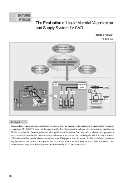
FEATURE ARTICLEThe Evaluation of Liquid Material Vaporization and Supply System for CVD The Evaluation of Liquid Material VaporizationTetsuo Shimizu* EATURE technology. The MOCVD is one of the most feasible thin film formation technique for ferroelectrics thin film forFRAM, capacitor film, insulating films and other high-functional thin film. Currently various substances are proposed asefficiently and stably vaporizes becomes very important. This paper reviews the various liquid material vaporization and ArMaterial bottleFTIRAr CVD chamber ·MixerO2 Pb Futurework Development of organic metal materialVaporization and Film formation and film characteristics SEC gas out LF310A HeatingTC Technical Reports devices become more miniaturized and denser, theand more precise. In particular, CVD allows forming aprovides better step coverage and high controllability.Table 1CVD are roughly classified into inorganic compoundsand organic
2 metallic compounds.Inorganic compounds
metallic compounds.Inorganic compounds are further classified intohydrides and halides. Hydrides and halides show highAs organic metallic compounds, alkoxy compounds,used. All of them show low vapor pressure and areunstable. For the CVD raw material supply system,therefore, it is an issue how efficiently these organicsupplied stably.Liquid Material Vaporization andinjection method. These methods have their own features, but3.1Bubbling Method. The liquid material is maintained at constantCVD chamber. When the liquid material is mixed with of the material can be expressed with the is the flow rate of the carrier gas;pressure in the bubbler.However, as heat of vaporization is removed, theRecently, however, the bubbling method has not been 1 InorganicHydrideSiH HalidesSiH, TiClOrganicAlkoxyTEOS, TEPO, TMB, metalliccompoundPETa Alkyl compoundTMP, TMAIComplex compoundSr(DPM) Table 1 Typical Raw Materials for CVD MFCMFM or
3 TCD FEATURE ARTICLEThe Evaluation of Liq
TCD FEATURE ARTICLEThe Evaluation of Liquid Material Vaporization and Supply System for CVD3.2Baking Methodhas been directly heated. Since the vapor generated from(TEOS), an alkoxy compound of silicon. However, it hasprocesses, (b) the equipment is large-scaled andexpensive, and (c) the footprint is large because the3.3Injection Methodamount. This method is classified into the columncolumn is charged with metallic particles to increaseeffectively vaporize the liquid. The equipment can becolumn and subsequent line. In the pressure reducingprocess, however, cavitation or the like can causeunstable generation of vapor. Hot Box downsized and low-priced. The gas-liquid interfacerapid rising and falling of material supply.been improved to increase the vaporization efficiency. LiquidGasMFC gasMFCSEC Vaporized gas Pressed LF310A TCHeating SEC gas out LF310A HeatingTC (a) Liquid Injection Method(b) Mix Injection MethodFig.4 Di
4 rect Injection Method Technical Reports
rect Injection Method Technical Reports Vaporization by Direct Injection Method4.1Evaluation of Vaporization Characteristics ofPETaTantalum oxide (TAgeneration semiconductor devices. Pentaetoxy tantalum(PETa) is used as material for Tapressure is approximately 20 Pa at 170°C. Vaporizationhigher. However, if the vaporization temperature is toohigh, thermal cracking might occur in the material. For was used to conductPETa.Fig.5Testing Equipment for EvaluatingVaporization Characteristics4.1.1Test Procedurechange the generated amount of PETa in a range betweenwas evaluated. The stability of vaporization wason the secondary side of the vaporizer, and the internalvaporizer. DRYER0.2MPaN2Ta(OC2H5)5, F.S. 0.5cm3/mN2, F.S. 3SLM He 4.1.2Test Results. The output from theinsufficient with droplets noted. The output was stable at/min when vaporization was sufficient. Somevaporization can be estimated from the output from theFig.6
5 Output from MFM and Internal State ofVap
Output from MFM and Internal State ofVaporization /m0.3cm/m0.4cm 4 FEATURE ARTICLEThe Evaluation of Liquid Material Vaporization and Supply System for CVD4.1.3Influence of Vaporization Temperature shows the changes that occurred in the outputsand flow rate of the vaporizer were changed. The risingamount of PETa decreases. When the temperature of thevaporizer is 180°C, PETa can be stably vaporized atFig.7 Influence of Vaporization Temperature4.2 Evaluation of Vaporization Characteristics offormation. The same flow as in the vaporization test ofPETa was used to conduct a TEPO[P(OCTable 2. Although the pressure condition is slightly different,the vaporization efficiency is greatly improved by themixing injection method. This indicates that a high flow 3m4m/m0.2cm/m0.3cm/m0.4cm/m0.5cm Flow rate ofAmount of TEPO vaporization ): 0.05(g/min) Condition:Vaporizer temperature 100°C : Good : Slightly bad Flow rate
6 ofAmount of TEPO vaporization ):(g/min):(g/min)")
ofAmount of TEPO vaporization ):(g/min) 0.150.1250.10.0750.05 Condition:Vaporizer temperature 100°C : Good : Slightly bad Table 2Characteristics of TEPO Vaporization byTable 3Characteristics of TEPO Vaporization by Technical Reports To continuously use the vaporizer for the bakingto automatically feed liquid material. As an example, ourTEOS automatic delivery system is introduced below. and Fig.8 Automatic Delivery System for Liquid Material Fig.9Flow of Automatic Delivery System for Liquid F P.SP.S1.Conforming to safety regulations [CE marking/SEMISTANDARD(S2)]2.Minimize footprint3.Safety design with automatic monitoring system4.Easy operation by using two way communication5.Non stop recharging at replacement of source tanks6.Best compatibility with LSC/VC systemmaterial will become more or more important. On theaccurately. We wish to take this opportunity of makingof the semiconductor industry.Tetsuo Shim