
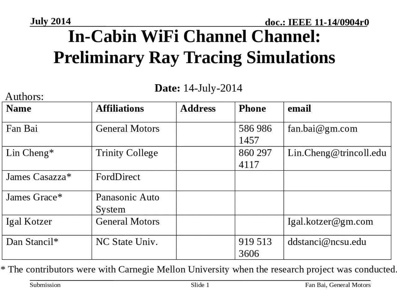
Slide 1 InCabin WiFi Channel Channel Preliminary Ray Tracing Simulations Date 14July2014 Authors The contributors were with Carnegie Mellon University when the research project was conducted ID: 1030749
Download Presentation The PPT/PDF document "July 2014 Fan Bai, General Motors" is the property of its rightful owner. Permission is granted to download and print the materials on this web site for personal, non-commercial use only, and to display it on your personal computer provided you do not modify the materials and that you retain all copyright notices contained in the materials. By downloading content from our website, you accept the terms of this agreement.


1. July 2014Fan Bai, General MotorsSlide 1In-Cabin WiFi Channel Channel: Preliminary Ray Tracing Simulations Date: 14-July-2014Authors:* The contributors were with Carnegie Mellon University when the research project was conducted.
2. Wireless on the goSource: http://www.internet-go.com/July 2014Fan Bai, General MotorsSlide 2
3. MotivationIn-cabin wireless networks are attractiveEnable passengers to use their own devices during road tripsImportant to obtain information about the wave propagation in the vehicle cabinIn-cabin use cases and corresponding scenarios should be considered for next-generation WiFi design.July 2014Fan Bai, General MotorsSlide 3
4. Challenges of In-cabin WiFi environmentsConfined spatial extentsCoupled with objects inside the cabinCommunication systems are required to operate without making drastic modifications to the environmentJuly 2014Fan Bai, General MotorsSlide 4
5. This workMeasures the RSSI values of WiFi channel (operated at 2.4 GHz) native to a mid-sized vehicle cabin enclosure Studies the wireless channel using ray-tracing mechanismPresents a simple simulation approachValidates simulations by comparison with measurementsJuly 2014Fan Bai, General MotorsSlide 5
6. Transmit: Patch AntennaFlat – easy to attach to roof/dash/seat, etcRadiates Perpendicular to Antenna – place on flat surface without loosing signalSimple DesignEasy to produceUnobtrusiveJuly 2014Fan Bai, General MotorsSlide 6
7. Receive: Dipole AntennaRadial – Easy to capture single polarizationVertical Design – ability to “probe” within the vehicleSimple DesignEasy to PrototypeJuly 2014Fan Bai, General MotorsSlide 7
8. Test Vehicle: a mid-size vehicleJuly 2014Fan Bai, General Motors8
9. Test Vehicle SetupTransmitting antenna: Patch antenna placed on dashboardEmpty vehicleJuly 2014Fan Bai, General MotorsSlide 9
10. Test ProcedureMeasured power received throughout the vehicle on a planar grid using a dipole antennaMeasurements made every half wave-lengthDipole can be oriented differently to observe the X, Y, and Z components of the fieldJuly 2014Fan Bai, General MotorsSlide 10
11. Dashboard Transmitter: Power loss (dB)July 2014Fan Bai, General MotorsSlide 11
12. Dashboard Transmitter: July 2014Fan Bai, General MotorsSlide 12
13. Dashboard Transmitter with Driver: Power loss (dB)July 2014Fan Bai, General MotorsSlide 13
14. Dashboard Transmitter with Driver: July 2014Fan Bai, General MotorsSlide 14
15. This preliminary study considersDashboard transmitter In-cabin geometry as a rectangular prismModel the existence of dominant reflections for various in-cabin surfaces (up to 5 rays)Image-based Ray-tracing methodSimplest model: angle independent antennasMore realistic: patch on dashboard with mobile dipoleJuly 2014Fan Bai, General MotorsSlide 15
16. Representative Mid-Size Vehicle ExampleA mid-size vehicleJuly 2014Fan Bai, General MotorsSlide 16
17. GeometryJuly 2014Fan Bai, General MotorsSlide 17
18. Simplest Model: Angle-independentAssume gains of both dash and mobile antennas do not depend on angleProduct of gains taken to be adjustable parameterKeep signs of images, but otherwise take reflection coefficients to be adjustable parametersKeep only specular reflections from sides, bottom, and topAssume always polarization matchedJuly 2014Fan Bai, General MotorsSlide 18
19. Simulation ExampleThe model is capable of generating the dB loss for any point in the cabinExample: consider deploying receiving devices at 2.4 GHz on a 52 by 25 grid with half-wavelength separations. This results in 1300 (52 by 25) grid locationsUsing the 1-ray(5-ray) model, we simulated the dB loss at these locations and generated a contour plot interpolated based on these simulated valuesJuly 2014Fan Bai, General MotorsSlide 19
20. Comparison of 1-ray with measurementsMeasurement: Patch & dipole polarized along YMeasurement plane 10 cm below patchGain product giving best LMS match to data: 2.4 dBRMS residual: 5.28 dBJuly 2014Fan Bai, General MotorsSlide 20
21. R=0.66RMS = 5.28 dBRMS=5.26 dBJuly 2014Fan Bai, General MotorsSlide 21Add Reflections to obtain same RMS residual with 1-ray
22. More Realistic Model: Patch + DipoleUse actual fields from Y-polarized patch on dashboardUse vector effective length of dipole mobile antennaAs before use gain-product and reflection coefficients as adjustable parametersConsider three orthogonal polarizationsJuly 2014Fan Bai, General MotorsSlide 22
23. Comparison of 1-ray with measurementsMeasurement: Patch & dipole polarized along YMeasurement plane 10 cm below patchGain product giving best LMS match to data: -0.4 dBRMS residual: 4.71 dBJuly 2014Fan Bai, General MotorsSlide 23
24. RMS=4.71 dBR=0.66RMS = 4.7 dBJuly 2014Fan Bai, General MotorsSlide 24Add Reflections to obtain same RMS residual with 1-ray
25. X PolarizationsJuly 2014Fan Bai, General MotorsSlide 25
26. Summary and ConclusionsDespite the multipath in the cabin, 1-ray (direct path) models perform reasonably well for co-polarized component (RMS error ~ 5dB)Crude model with angle-independent gain only about ½ dB worse RMS error than using actual fields from patch & dipoleSingle specular reflections can be used to generate fluctuations with similar RMS values and distributions as those measuredEmpirically, it appears depolarization from scattering dominates much of the region of interest for cross-polarized components, so specular-reflection models are less useful.July 2014Fan Bai, General MotorsSlide 26
27. References[1] M. Peter, R. Felbecker, W. Keusgen, J. Hillebrand "Measurement-based investigation of 60 GHz broadband transmission for wireless in-car communication." Vehicular Technology Conference Fall (VTC 2009-Fall), 2009 IEEE 70th. IEEE, 2009.[2] P. Smulders, "Exploiting the 60 GHz band for local wireless multimedia access: prospects and future directions, " Communications Magazine, IEEE, vol.40, no.1, pp. 140-147, 2002.[3] M. Peter, W. Keusgen, and M. Schirrmacher, "Measurement and analysis of the 60 GHz in-vehicular broadband radio channel, " in Vehicular Technology Conference, 2007. VTC 2007-Fall. 2007 IEEE 66th, Sep.-Oct. 2007.[4] P. Wertz, D. Zimmermann, FM Landstorfer, G. Wolfle, and R. Hoppe, "Hybrid ray optical models for the penetration of radio waves into enclosed spaces," in IEEE Vehicular Technology Conference, 2003, vol. 1, pp. 109-113.[5] M. Heddebaut, V. Deniau, and K. Adouane, "In-vehicle WLAN radio- frequency communication characterization," Intelligent Transportation Systems, IEEE Transactions on, vol. 5, no. 2, pp. 114-121, 2004.[6] O. Delangre, S. Van Roy, P. De Doncker, M. Lienard, and P. Degauque, "Modeling in-vehicle wideband wireless channels using reverberation chamber theory," IEEE Vehicular Technology Conference, pp. 2149-2153, 2007.[7] F. Bellens, F. Quitin, F. Horlin, and P. De Doncker, "UWB channel analysis within a moving car, " The 9th International Conference on Intelligent Transport Systems Telecommunications (ITST), 2009. IEEE, pp. 681-684.[8] Y. Katayama, K. Terasaka, K. Higashikaturagi, I. Matunami, and A. Kaji- wara, "Ultra-wideband impulse-radio propagation for in-vehicle wireless link," IEEE Vehicular Technology Conference, VTC-2006 Fall. 2006.[9] Y. Nakahata, K. Ono, I. Matsunami, and A. Kajiwara, "Performance evaluation of vehicular ultra- wideband radio channels, " IEEE Vehicular Technology Conference, 2008. VTC 2008-Fall, pp. 1-5.[10] J. Mar, Y.-R. Lin, and Y.-co Yeh, "Ultra-wide bandwidth in-vehicle channel measurements using chirp pulse sounding signal," IET Sci. Meas. Technol., vol. 3, iss. 4, pp.271-278, July 2009.[11] T. Kobayashi, "Measurements and characterization of ultra wideband propagation channels in a passenger-car compartment," IEEE ISSTA 2006, pp.228-232, Aug. 2006.[12] M. Schack, J. Jemai, R. Piesiewicz, R. Geise, I. Schmidt and T. Kurner, "Measurements and analysis of an in-car UWB channel," Proc. IEEE Vehicular Technology Conference 2008-Spring, pp.459-463, May 2008.July 2014Fan Bai, General MotorsSlide 27