
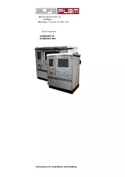
Ltd VRANJE Radnička 1 Phone 017 4 21 121 Solid fuel stove DOMINANT 70 DOMINANT 90H Instructions for installation and handling Fig 1 Solid fuel stove DOMINANT 70 DOMINANT 90H 1 D ID: 845239
Download Pdf The PPT/PDF document "METAL INDUSTRY" is the property of its rightful owner. Permission is granted to download and print the materials on this web site for personal, non-commercial use only, and to display it on your personal computer provided you do not modify the materials and that you retain all copyright notices contained in the materials. By downloading content from our website, you accept the terms of this agreement.


1 METAL INDUSTRY Ltd.
METAL INDUSTRY Ltd. VRANJE Radnička 1 , Phone : 017/ 4 21 - 121 Solid fuel stove DOMINANT 70 DOMINANT 90H Instructions for installation and handling Fig. 1 Solid fuel stove DOMINANT 70, DOMINANT 90H 1. Door of the firebox 2. Door of the ashtray 3. Air regulator 4. Drawer for fuel 5. Later al flue connection 6. Double - glass oven door 7. Protective cover of the opening for cleaning INSTRUCTIONS FOR INSTALLATION, USE AND HANDLING Th ese instructions for installation, use and handling apply to the following types of stoves: DOMINANT 70 , DOMINANT 90 H In general, one must adhere to the heating regulations in the country , as well as to all necessary local, national and European norms and regulations. Important prior to use * In order to have a properly functioning stove it is important to carefully read these instructions and to precisely follow the guidelines within it. * Use only recommended types of fuel, be e ch wood, brown coal. 1 6 7 2 5 3 4 1 2 3 4 5 6 7 * The required pressure in the flue, during normal operational load should be ca. 12 Pa. In the case of load above 15 Pa, a damper should be embedded in the flue. * You must make sure that the space where the device is placed for stoking gets suffici ent supply of fresh air. If the windows and the doors are sealed, or if other devices such as a steam vacuum cleaner, clothes dryer, extractor fan etc. are located in the space where the stove is installed, and they take away the air, th e n in such circumst ances the combustion air (fresh air) should be brought from outside. Anyway, in that regard , before the installation of the stove you should talk to a competent chimney sweep. * No flammable materials should be kept in the ashtray. The height of ash filling must not exceed the height of the lateral walls of the ash drawer. *The door of the firebox and the door of the ashtray must be constantly closed (except during kindling, during fuel filling and when ash is taken out) in order to prevent the escape of flue gases. * No components of the stove may be replaced with components other than tested original components and accessories offered by us or our service. *In the event of fire in the flue, keep the stov
2 e door closed and set the air regulat or
e door closed and set the air regulat or to ze ro. Never attempt to extinguish fire in the flue with water. Abrupt creation of water steam may cause the flue cracking. If necessary, call fire - fighters. 1. TECHNICAL DATA ---------------------------------------------------------------------------------------------------- -------------------------------------------- UNIT DOMINANT 70 DOMINAN T 90 H ---------------------------------------------------------------------------------------------------- ---------------------------------- ---------- Rated heating capacity ( kW ) 6,3 6,5 ----------------------------------------------------------------------------------------------------------------------------- ---------------- Temperature of waste gases (º C) 205 in cleaved wood 179 in cleaved w ood 180 in brown coal briquettes 149 in brown coal briquettes ------------------------------------------------------------------------------- ----------------------------------------------------------- Required pressure in the flue ( Pa ) 12 12 --------------------------------------------------------------------- ---------------------------------------------------------------------- Dimensions of the stove 700x600x850 700x600x 850 (width x depth x height) mm ------------------------- ----------------------------------------------------------------------------------------------------------------- Dimensions of the oven 330x440x260 330x440x2 60 (width x depth x height) mm ----------------------------------------------------------------------------------------------------------------------------- ------------- Diameter of the flue extension ( mm ) 120 120 ----------------------------------------------------------------------------------------------------------------------------- ------------- Height from the floor to the back side 43 2 back side 432 axis of the flue extension (mm) laterally 690 laterally 690 ---------------- -------------------------------------------------------------------------------------------------------------------------- CO(%) 0,880 in cleaved wood 0,96 in cleaved wood 0,309 in brown coal briquettes 0,249 in brown coal briquettes ----------------------------------------------------------------------------------------------------------------------------- -------------
3 --
-- Degree of utilization (%) 76,4 in cleaved wood 76,3 in cleaved wood 79,1 in brown coal briquettes 77 in brown coal briquettes ----------------------------------------------------------------------------------------------------------------------------- ------------ Weight ( Kg ) 126 . 5 146 . 5 ----------------------------------------------------------------------------------------------------------------------------- ---------------- 2. INSTALLATION OF THE STOVE During the installation of the stove you should pay attention to valid regulations in regard to valid civil engineering and fire preventi on regulations and provisi ons. The installation of the stove must be performed by a professional installer . The connection of the stove to the flue is performed from the sides, at the back side and on the top left or right. This depends on whether you ha ve chosen a ‘left’ or ‘right’ stove. Pay attention to the spot where the stove is installed, it should be horizontal. If the floor is flammable (wood, plastics, carpet…), you should use steel sheet metal or copper or some other non - flammable material. This base must exceed the basic outlines of the stove by at least 30 cm and on the side where the stove is handled it should exceed this side by 50 cm. The distance between all the sides of the stove and the parts of furniture made of wood or plastics is at least 20 cm, while the d istance from the lateral sides must be at least 30cm. Embedded parts made of flammable material s must be at a distance of at least 80cm from the opening for filling the stove towards the sides. Safe distance for objects that should be protected (walls whi ch might be ignited, walls with components that might be ignited, kitchen cabinets and bearing walls of steel concrete) is at least 20cm, while the distance from the lateral sides must be at least 30cm. Around the stove , you should provide sufficient distance in relation to flammable objects (that have wooden coating, furniture, curtains etc.). No upgrading is allowed above the stove, when the steel plate of the stove is use d . When moving the wa ste gases exhaust pipe, you should keep a minim um distance of 40cm in relation to flammable matters : Before connecting the stove to the flue you must consult a chimney sweep. The connection of the stove to the flue is performed with appropriate connection parts according to SRPS.M.R4.031 (DIN 1298. or DIN EN 1856 - 2). One must make sure that the connecting joint of the flue , as well as the flue pipe , do not intersect with waste gases and that they are properly sealed. In general, one should pay at tention to DIN 18 160. For chimney measurement, EN 13 384 applies. If you want your stove to achieve the desired capacity, you must ensure that the installation is performed properly and above all that the flue function s flawlessly. In any case, you should check the existing pressure in the flue, prior to commissioning the stove
4 . The easiest way to control the stren
. The easiest way to control the strength of flue draught is by keeping the flame of a candle under the opening of the flue. The draught is sufficient if the candle flame bends towar ds the opening of the flue. Slow bending of the flame is an indicator of poor draught. If two heating devices are installed on one floor and on one flue (multiple load s ) the distance between the connections must not be less than 50 cm. 3 . AIR REGULATION Fig. 2 3. 2. PRIMARY AIR The primary combustion air, thereby the capacity of heating of the stove is determined with the primary combustion air. This air is regulated by means of the regulator for primary air on the ashtray door (figure 1 position 3 ). The knob on the ashtray door (figure 2 pos ition 9) shows the direction of opening and closing of the slide rule. For kindling, the air regulator should be maximally open (put the knob in position 3) . Note: In order to prevent overhearing of the stove, it is not allowed that the quantity of fuel is more than 1,8 kg dry wood or 1,7 kg brown coal briquettes per one hour at an appropriately adjusted combustion – air. 3. 2 HEATING FLAP Fig . 3 Moving of the heating flap is performed by activating the knob (figure 3 , position 11) which is positioned above the oven door. It is used for shortening of the path of flue gases during stoking. Open the heating flap only in a stage of kindling of the stove. 9 11 During stoking, if the heating flat is left open, it will cause overheating of the stove, thereby damaging the parts of the stove. In addition , open heating flat results with bigger consumption of fuel. Pull out the knob = the heating flap is open Push in the knob = the heating flap is closed 3.3 OVEN D OOR (Figure 1, Position 6) The oven door can be in one of the two desired positions depending on the desired warmth in the room. Over door open: h igher heat emission for heating the room. Oven door closed: lower heat emission for heating the room. The oven door can be removed without tools: you should grab the handle and pull the slightly open door upwards. It can be placed back by inserting both hinges in the corresponding openings, at the front side of the oven and use pressure on the lower door e dge with a knee , simultaneously lightly pulling the handle up. When the stove is in operation, the oven door must be installed 3. 4 Fuel drawer ( f ig ure 1 position 4), In the lower part of the stove there is space for fuel, with guides and it is easy to lift it. Attention: Do not store easily flammable materials such as paper etc. in that space. Pay attention to the height when filling. 4. STOVE COMMISSIONING Prior to the first stoking, all enameled surfac es should be cleaned with a soft dry towel, in order to prevent creation of stains. After becoming familiar with the handling of the stove, the first commissioning can take place . During the first stoking, open the window since the applied corrosion protection in a short time develops an unpleasant however insignificant smoke, that is, an u
5 npleasant smell is created. This is norm
npleasant smell is created. This is normal and it disappears after a short time. Consider that some built - in parts of the stove (pipe for waste gases, door for fill ing etc.) , when it is kindled, may be hot and represent danger of burns. Special attention should be paid to little children, so that no danger occurs. At the first stoking, stoke the stove for two or three low fires in order to prevent cracking of the fir eclay. 4.1 STOKING * Pull out the heating flap knob, the heating flap is open. * Open the primary air regulator at the highest level of air release ( figure 3, position 9 ) * Open the firebox door * Insert wood wool, sawdust or paper * O ve r this, put 2 - 3 small wood pieces * Ignite * Close the door of the firebox * Let the wood burn lively * P ress in the heating flab knob, the heating flap is closed. 4.2 FIREBOX Upon creating the basic ember, you need to add fuel in the opening for filling. Position the air regulator on the appropriate marked position (put the knob in position 1 - 3). When adding fuel, s lightly open the door of the firebox without pulling out flue gases, in this manner you will avoid having flue gases in the room. The rated heating capacity is achieved when you put the next fuel quantity and you adjust: Fuel F uel quantity T ime of combustion Adjusting the primary air Cleaved wood 1, 6 kg 2 short logs 1,0 h Degree 1 /2 B rown coal briquettes 2,7 kg 6 whole rock 2,0 h Degree 1 Make sure than you never put more wood or briquettes than what is really required for the rated capacity of heating. The above indicated fuel quantity must not be exceeded because this may cause overheating of the stove. Only natural dry wood or brown coal briquettes may be used according to the regulations on emission protection. The wood being used must be dry (humidity residual, 20%) . This is usually the case when wood is stored for two years in a dry spot where there is good ventilation. Wet wood has lo w calorific value and causes soot deposits in the flue channels and in the flue. Wood with treated upper surface (coated, painte d , veneered and impregnated ) , plywood, waste of any kind (waste from packaging), plastics , paper, rubber, leather, textile etc. must not be stoked. The combustion of such materials pollutes the environment and it is prohibited by law. Besides this, damages of the flue may also occur. In this case, all kinds of guarantee by the manufacturer cease. Unfavorable conditions and insuffic ient draught in the flue my cause obstructions so the flue gases are not entirely taken away. In this case you should create draught as a decoy in the flue. If this measure does not create draught in the flue, than it is not allowed to use the stove for sa fety reasons. Note: Better usability of fuel, thereby better heating of space is established by slightly or completely opening the oven door. 4.3 COOKING 4.3.1 COOKING DURING SUMMER During warm days, the stove on solid fuel is used mainly for cooking. The oven door is kept closed. The best is to use a pot with a heavy bottom and a corresponding cover. 4.3.2 COOKING DURING WINTER During cold days, the solid fuel stove is used mostly for heating of rooms. In order to cook faster, use dry woods. The heat ing flap must be closed and the air regulation must be maximally open. After you finish cooking, you should put the air regulat or in a position denoted for r
6 ated heat capacity. 4.4 BAKING COOKI
ated heat capacity. 4.4 BAKING COOKIES AND BAKING PASTRY For baking cookies and baking pastry, eve nly distributed heat is required. In order to achieve this evenness and sufficiently high temperature, the oven must be closed with a closed heating flap , d epending on what is being baked, the oven must be heated in advance. It the stove has heated up to t he desired temperature, but what you plan to bake inside the oven. Do not let creation of very strong ember, you should rather frequently add fuel in small quantities. Put high baking molds in the lower groove of the oven. You should bake all cookies with such shape on a moderate temperature. For flat cookies or pastry , both grooves may be used. During this, we recommend slightly higher oven temperature. For baking pasty you need importantly higher temperature than when baking cookies. Hence, the time of preparation (with prior warming) is necessar ily a bit longer … 4.5 STOKING IN A TRANSITORY PERIOD At outdoor temperatures above 15ºC , on the basis of low transporting pressure, small fire in the flue is created . This creates more soot in the flue channels of the stove and the flue. Increase the inflow of primary air and make more frequent ember burning and more frequently add small pieces of cleaved wood in order to reduce the soot in the transitory period. 5. MAINTENANCE AND CLEANING OF THE STO VE Regular maintenance and care such as cleaning of the stove, the flue channels and flue extension is important for safe operation , thriftiness and preservation of the stove value . Maintenance of enameled surfaces of the stove is recommended only in cold state. The stove is cleaned with clean water and soft towel and in s pecific cases, with s oap as well. The cleaning intervals depend mostly on the use of fuel, the period of use of t he stove and the manner of its use. Unnecessary creation of dust may be avoided, if the following sequ ence of cleaning is maintained: * Removal of the cooking plate and thorough cleaning of the same outside. * Cleaning soot deposits from the upper side of the oven and in parts where flue gases pass. * Placing the plate. * Opening of the protective cover for cleaning (below the oven door) and removal of the cover. * Removal of soot and ash with a partitioning sheet metal. * Removal of soot and ash from the stove bottom. * Tightening the cover at the front side and closing the protective cover. NOTE: During stoking of the stove, make sure that the door glass of the firebox does not become smoky. Smoke is created due to bad combustion, for many reasons. Bad draught of the flue (bad flue), the stove is improperly used, for example, the supply of oxygen is dampened too early. We cannot influence on these factors. For this reason we do not provide a guarantee for clean glass. 5.1. OPENING FOR CLEANING Fig. 6 12 Behind the protective cover of the opening for cleaning, there is a cover (figure 6 position 1 2 ). It is fastened with a butterfly nut at the front side of the stove and in order to clean the internal part of the stove, it should be removed. Before re - screwing it, you need a sealing braid which is on the cover in order to control the sealing, and i f necessary, it should be changed. 5.2 MAINTENANCE AND CLEANING OF THE COOKIING PLATE For cleaning of the cooking plat
7 e, use small sandpaper or abrasive. And
e, use small sandpaper or abrasive. And during cleaning of the plate, wipe it with a semi - wet towel and in the end with a dry towel. Make sure that the stretching grooves on the cooking plate remain free with no crust, in order to enable stretching of the plate as an action of heat. Baked fo od scraps or parts of slag in the grooves may cause deformation of the cooking panel. Do not leave pots or pans on the cold cooking plate. Edges may be created by corrosion, which are difficult to remove. 5.3 REMOVAL OF SLAG AND ASH Slag is removed with t he supplied accessories, with blade for ash . The ashtray should be emptied on a regular basis prior to e ach kindling. You should clean the trash rack 1 - 2 times per week. It the air openings are clogged with slag, crust or some other burning remains, take o ut the trash rack and clean it. 5.4 GENERAL NOTES If you follow the instructions for installation and handling, the stove represents safe household appliance. All drawbacks of Your stove can be removed at our customer service department. For complaints re lated to mistakes which occur or drawbacks in terms of functionality, contact our customer service department. The same help s in the supply of spare parts (it uses only original parts). The entire stoking unit must be regularly inspected by an expert. 6. TIME OF GUARANTEED SERVICING This implies the period during which we guarantee the service, accessories and space parts, starting from the day of purchase of the device. The time of guaranteed servicing is in accordance with the valid legal regulations. In case of change of the model and the design of the device, the term for change of parts that have modified design is within the legal term. After this term we provide the modified pa rts in the new designs. 6.1 CONDITIONS OF THE GUARANTEE The guarantee of the product is valid within the legally defined term. The guarantee is not valid for the glass, the glass - ceramic panel and the physical damages that have occurred after purchase. THE MANUFACTURER RETAINS ALL THE RIGHTS TO MAKE CHANGES. The device will properly function within the guaranteed term only if it is used in accordance with these guidelines for connection and application. The guarantee cases to apply if it is determined that: - the connection or the repair of the product was performed by an unauthorized person, that is, if unoriginal parts have been embedded, - if the device has not been properly used in accordance with these guidelines, - if some mechanical damaging of t he device occurred during usage, - if the repairs of defects were performed by an unauthorized person, - if the device has been used for commercial purposes, - if the damage has occurred during transportation after the device was sold, - if the defects occ urred due to improper mounting, improper maintenance or mechanical damaging by the buyer, - if the defect occurred after too strong or insufficient power, as well due to force major. We can repair the defects of Your device also outside the guaranteed per iod, with original spare parts for which we also provide a guarantee under the same conditions. This guarantee does not exclude or affect the rights of the customer in regard to the conformity of the goods pursuant to the legal regulations. If the delivere d product does not conform to the agreement, the customer has the right to ask the seller to repair that lack of conformity without any reimbursement, by repair or change of the product in accordance with the valid legal regula