

Interconductor Contact Resistance Values in Coated Conductor Stacks and Roebel Cable at Variable Temperatures C J Kovacs 1 M D Sumption 1 E Z Barzi 2 D Turrioni 2 V S Kashikhin ID: 783152
Download The PPT/PDF document "Direct Measurement of Modified" is the property of its rightful owner. Permission is granted to download and print the materials on this web site for personal, non-commercial use only, and to display it on your personal computer provided you do not modify the materials and that you retain all copyright notices contained in the materials. By downloading content from our website, you accept the terms of this agreement.


Slide1
Direct Measurement of Modified Interconductor Contact Resistance Values in Coated Conductor Stacks and Roebel Cable at Variable Temperatures
C. J. Kovacs1, M. D. Sumption1, E. Z. Barzi2, D. Turrioni2, V. S. Kashikhin2, M. Majoros1, E. W. Collings1
1 Center for Superconducting & Magnetic Materials (CSMM), Department of Materials Science & Engineering, The Ohio State University, USA2 Applied Physics and Superconductivity Technology Division (APS-TD), Fermi National Accelerator Laboratory, USA
Acknowledgments
This work was supported by the U.S. Department of Energy, Office of Science Graduate Student Research Program (SCGSR)
Low-T diffusion bond processing was performed on
ReBCO
Roebel
cable.
A small decrease in ICR was seen for processing of 150 °C x 3
hr
@ 2.7 MPa and 240 °C x 6
hr
under pO
2 @ 2.7 MPa.Cable flexibility decreases with diffusion bonding and cable precleaning and other preparation may be required for stronger bonding.Chromium plating increased resistance and maintained cable flexibility.Chromium plating needs to be performed on a disassembled Roebel cable to ensure an even electrodeposited layer.
Conclusions
[1] M. Majoros, M.D. Sumption, E.W. Collings, and N.J. Long, “Stability, Inter-Strand Contact Resistance, and AC Losses in YBCO Roebel Cables,” IEEE Trans. on Appl. Supercond., vol. 24, no. 3, 2014.[2] T. Lecrevisse et. al., Metal-as-insulation variant of no-insulation HTS winding technique: pancake tests under high background magnetic field and high current at 4.2 K”, SUST, vol. 31, 14pp, Art. no. 055008, 2018.[3] A.B. Kaiser, “Electronic transport properties of conducting polymers and carbon nanotubes”, Rep. Prog. Phys., vol. 64, pp. 1-49, 2001[4] Y.S. Jo et. al., “Electrical characteristics of smart insulation 2G HTS coils based on three fabrication methods”, IEEE Trans. Appl. Supercond., vol. 29, no. 5, 2019, Art. no. 4601505.[5] E.W. Collings, M.D. Sumption, D.R. Dietderich, Y. Ilyin, and A. Nijhuis, “Influence of pre-heat-treatment condition on interstrand contact resistance in Nb3Sn Rutherford cables by calorimetric AC-loss measurement,” AIP Conference Proc., vol. 824, no. 1, pp. 851-858, 2006.[6] J. Lu, R. Goddard, K. Han, and S. Hahn, “Contact resistance between to REBCO tapes under load and load cycles”, SUST, vol. 30, 8pp, 2017, Art. no. 045005.[7] J. S. Lamas, C. A. Baldan, C. Y. Shigue, A. Shilhanek, and V. Moshchalokov, “Electrical and magnetic characterization of BSCCO and YBCO HTS tapes for fault current limiter application”, IEEE Trans. Appl. Supercond., vol. 21, no. 3, pp. 3398-3402, 2011.[8] S. E. Russek, S. C. Sanders, A. Roshko, and J. W. Ekin, “Surface degradation of superconductivity YBa2Cu3O7-δ thin films”, Appl. Phys. Lett., vol. 64, no. 26, pp. 3649-3651, 1994.[9] R. Holm, Electric Contacts: Theory and Applications, 4th ed., New York, NY, USA: Springer Verlag Berlin Heidelberg GmbH, 1967.
References
Many next generation high-field magnets and applications have been designed to utilize REBCO coated conductor to maintain large Je in the presence of large magnetic fields.Multiple REBCO cable insulation composite strategies have been fabricated to meet the demands of a high Je while keeping AC-loss, inductance, and stored energy of large windings to a minimum.As wound, the interconductor contact resistance (ICR) of some REBCO cable designs will have negligible current sharing [1]. While this will decrease AC-Loss, stability and current sharing will also decrease without additional processing.Similar to LTS cables, a balance needs to be pursued to find an acceptable level of ICR.REBCO cables and coils can also have excessive current sharing.This can be reduced with low RRR resistive metal layers/coatings [2] or Metal-to-Insulator-Transitioning (MIT) “smart” layers [3,4]. Low-temperature diffusion bonding and electrodeposited coatings have been a proven method to control ICR in LTS cables and this methodology has been pursued for REBCO cables by OSU [5].Even very thin coatings can change ICR drastically, introducing a means to optimize stability and current sharing with little penalty to Je of the winding.
Introduction
A single lap joint was created with 14 mm wide as received SuperPower REBCO coated conductor.Measurements were performed at:77 K and 200 MPa4.2-300 K and 20 MPaTests: Cr, Ni, Nicklon (Ni-PTFE), As-rec Cu and Ag w and w/o DexMat CNT insert (heat treated under Ar at 400 C and as-is)The CNT insert was investigated as a Metal-to-Insulator material (near REBCO Tc) for permitting high ramp rates and current sharing during quench.
REBCO Roebel cable
For this study, Roebel cable received from KIT was used. The properties of this cable are shown below.The 9-tape cable was pressed in a fixture over a length of 300 mm.Tapes 1 and 5 were revealed on both ends of the fixture to transfer current across the entire cable.Measurements were performed in a LN2 bath.
REBCO coated conductor stacks at 77 K and 4.2-150 K
ParameterSpecificationRoebel cable manufacturerKarlsruhe Institute of TechnologyREBCO tape manufacturerSuperPower Inc.Type of Roebel cable9/5.6Number of Tapes9Tape Width, wtape (mm)5.6Cable Width, WC (mm)11.8Tape thickness, ttape (mm)0.1Pitch Length, Lp (mm)126Cross-over angle, ϕ (degrees)30LInter-strand gap (mm)0.4WCross-over (mm)5.6Ic @ 77 K, sum of tapes (A)1168
Roebel
Cable ICR measurement results at 77 K
A small decrease in
ICR was seen for low-temperature diffusion bonding processing with (150 C / 2.7 MPa); this shouldn’t negatively degrade superconducting properties.Cable flexibility decreases with diffusion bonding and the bonding has low adhesion.Chromium and Nickel plating results in a higher ICR optionSilver plating results in a very low ICR option, possibly useful near current injectionEven when pressed with a 75x lower pressure than a lap joint, Roebel cable results in a significantly smaller ICR than the lap joint.Nicklon (Nickel-Teflon nanocomposite) is a low-friction, durable, chemically resistant coating that results in ICR values similar to as-received Cu-Cu lap jointsCNT tape functions as a high-tensile strength, thin, easy to implement, and low-friction “smart” insulationFor some samples, the Tc extended to 75 K. Tc degradation near 77 K can greatly increase the measured ICR.
Tue-Mo-Po2-10-04 [76]
General microstructure of
NicklonPTFE Dia = ~30 nm
General microstructure of aligned Carbon nanotube consolidations
The pressed (2.7 MPa)
Roebel
cable native copper layer had a much lower
ICR
than the pressed (20 MPa) coated conductor native copper stack. This may be due to differences in internal geometry, e.g.
Roebel
cable introduces shear to internal surfaces when pressed perpendicular to the cable face. Such shear stresses would break up oxide layers more effectively than a single perpendicular press in a stack.
During variable temperature measurements, the measured 16 K transition width is 10 K broader than similar measurements performed in [6] and much broader than resistive transition measurements performed along the A-B plane of the coated conductor length [7]. Because longitudinal resistance measurements have the external REBCO surface totally in parallel with the current carrying direction, any surface
Tc
degradation would go unnoticed. For lap joints, the YBCO surface plays a strong role in the measured joint resistance because the surface is partially in series with the current carrying direction. Any small amounts of external surface REBCO
Tc
degradation due to manufacturing, stresses, or storage conditions should therefore be strongly noticed in temperature dependent contact measurements [8].
Hard surface coatings resulting in a larger contact resistance is expected from Holm contact theory of pressed contacts [9]. This would explain the Nickel vs.
Nicklon
result.
ICR for coated conductor lap joint At 20 MPa in 4.2-150 K He-gas
10x
5x
5x
*100x
*100x
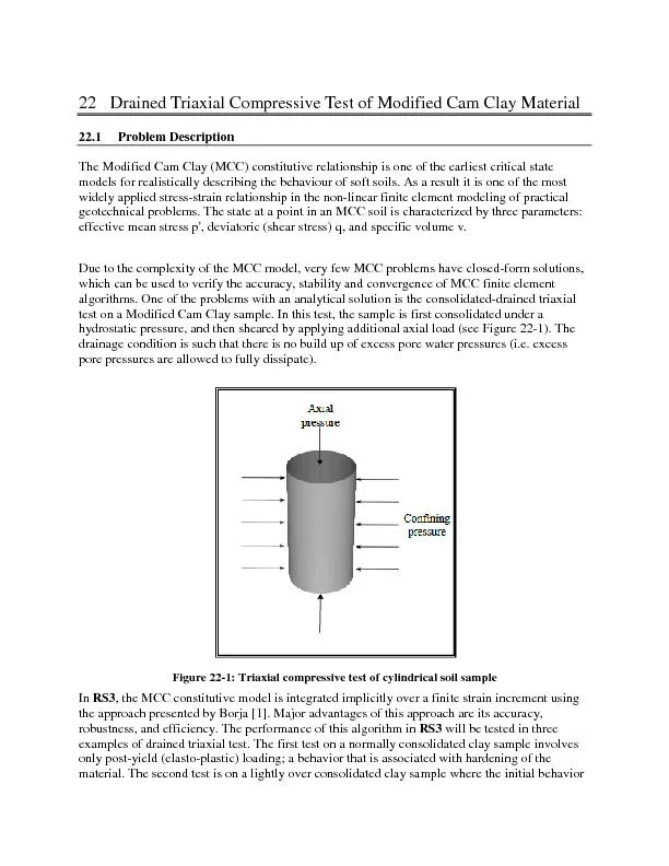
Discussion