
Cylinders SO 60201 cylinders for working pressures up to 160 bar Parker Hannifi n Cylinder Division Watford Herts Catalogue HY071215UK Roundline Cylinders MMB Series Contents Page Introduction ID: 942741
Download Pdf The PPT/PDF document "MMB Roundline" is the property of its rightful owner. Permission is granted to download and print the materials on this web site for personal, non-commercial use only, and to display it on your personal computer provided you do not modify the materials and that you retain all copyright notices contained in the materials. By downloading content from our website, you accept the terms of this agreement.


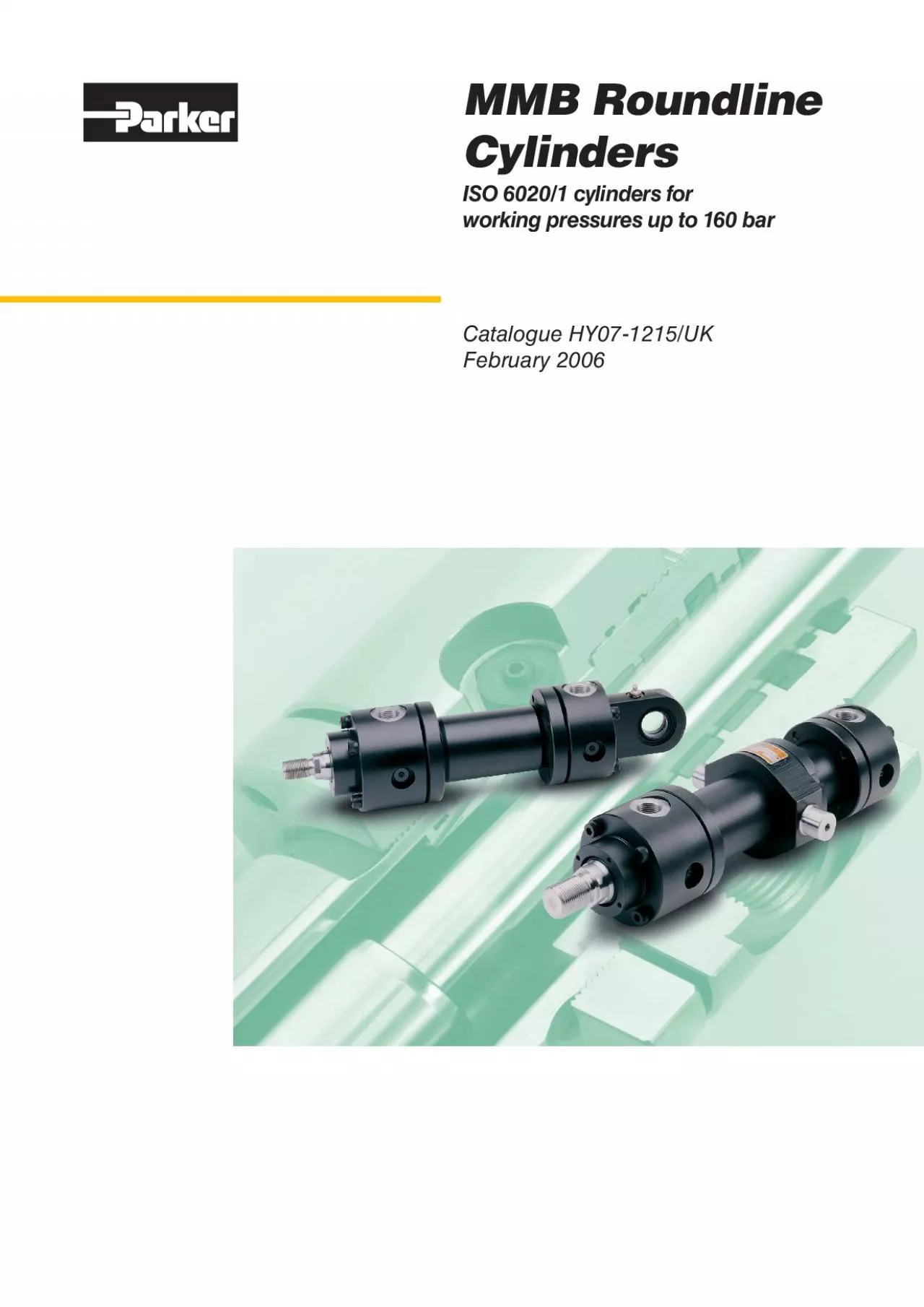
MMB Roundline Cylinders SO 6020/1 cylinders for working pressures up to 160 bar Parker Hannifi n Cylinder Division Watford, Herts. Catalogue HY07-1215/UK Roundline Cylinders MMB Series Contents Page Introduction Design Features and Benefi ts Rectangular Flange Mountings Round Flange Mountings Pivot Mountings Foot and Trunnion Mountings Piston Rod End Data Accessories Calculation of Cylinder Diameter 10 Mounting Information 10 Gland and Piston Seal Options 10 Piston Rod Size Selection 11 Long Stroke Cylinders 11 Stop Tubes 12 Stroke Factors 12 Cushioning 13 Seals and Fluids 15 Cylinder Masses 15 Ports 16 Replacement Parts and Service 17 How to Order Cylinders 19 Introduction Note: In line with our policy of continuing product improvement, specifi cations in this catalogue are subject to change without notice. Introduction The Series MMB roundline or hmillh cylinder delivers continuous high performance with low whole-life costs in arduous applications such as steel mills, where a rugged, durable cylinder with a hcleanh external design is reRuired. In addition to the standard cylinders featured in this catalogue, MMB cylinders can be designed and manufactured to suit individual customer reRuirements. Our engineers will be pleased to discuss and advise on uniRue designs to suit specifi c ap
plications. Parker Hannifi n Corporation is a world leader in the manufacture of systems and components for motion control. Parker has more than 800 product lines for hydraulic, pneumatic and electromechanical applications in some 1200 industrial and aerospace markets. With more than 50,000 employees and over 200 manufacturing plants and administrative offi ces around the world, Parker provides customers with technical excellence and fi rst class customer service. Parker Hannifi nhs Cylinder Division is the worldhs largest supplier of hydraulic cylinders for industrial applications. Parker cylinders are used in applications as diverse as machine tools, fl ight simulation and tidal barrier control. Visit us at www.parker.com/uk Standard Specifi cations Heavy Duty construction Styles and dimensions to: CETOP RP58H, ISO 6020/1 Rated pressure: 160 bar Fatigue-free at the rated pressure Hydraulic mineral oil – others on reRuest Temperature range of standard seals: -20 C to 80 Construction: head and cap bolted to heavy steel fl anges Bore sizes: 40mm to 320mm Piston rod diameters: 22mm to 220mm 11 10 10 Parker Hannifi n Cylinder Division Watford, Herts. Catalogue HY07-1215/UK Roundline Cylinders MMB Series Design Features and Benefi ts 1 Piston Rod Manufactured from precision ground, high ten
sile carbon steel for long working life, piston rods are hard chrome plated and polished to 0.2 m max. All rod and piston assemblies have a minimum of 4:1 safety factor at the smallest cross sectional area, based on tensile strength at rated pressures. 2 Head and Cap Retention The head and cap are bolted to heavy steel fl anges, which are retained by threads at each end of the cylinder body. 3 Cylinder Body The heavy wall steel tubing is honed to a high surface fi nish, to minimise internal friction and prolong seal life. 4 & 5 Head & Cap Ends The head and cap are machined from steel and located into the cylinder bodyhs internal diameter for added strength and precise alignment. To ensure leak-free performance, both are sealed by hOh rings which are, in turn, protected by anti-extrusion rings. 6 & 7 Cushioning Optional cushions are progressive in action, providing controlled deceleration which reduces noise and shock loading, and prolongs machine life. The head end cushion is a self-centring sleeve, while the polished cap end spear is an integral part of the rod. Needle valves are provided for precise cushion adjustment. Integral check valves minimise restriction to cylinder motion at the start of a stroke, allowing the rapid development of full piston speed for high cycling performance. For gre
ater operator safety, the cushion needle valves are retained to prevent inadvertent removal. 8 Rod Gland and Bearings The detachable steel rod gland features heavy duty polymer bearing rings to resist side loadings. Wide separation of these rings reduces bearing stresses, maximising the service life of the bearing. The polymer bearing rings, with the rod seals, are easily replaced on removal of the rod gland, and all components may be serviced without further disassembly of the cylinder. 9 Gland Seals The gland seals are located in a detachable gland housing for Ruick, easy maintenance, and provide effi cient retention of pressurized fl uid while preventing the ingress of contaminants. 10 Piston Seals Standard and chevron-type piston seal options are available, to suit different applications – see page 10. In addition, MMB cylinders can be designed and manufactured to suit individual customer reRuirements. Please contact the factory for details. 11 Body End Seals To ensure leak free performance, body end seals and gland/ head seals are of radial construction, avoiding the problems of hnibblingh and early failure associated with face-type seals. Optional Features Low friction seals High temperature seals Special materials Special paint fi nishes Alternative rod threads Maintenance free spherica
l bearings Air bleeds Gland drains Ports Position feedback Position switches Double rodded cylinders Rod bellows Metallic rod wipers Marine specifi cation materials and fi nishes Special Designs Parkerhs design and engineering staff are available to produce special designs to incorporate customerhs specifi c reRuirements. Alternative sealing arrangements, special mounting styles, higher or lower rated pressure designs, welded cap ends to reduce overall length (non-cushioned only), larger cylinder bores and alternative rod sizes are just a few of the special reRuirements which can be accommodated. Servicing Features All cylinders will, at some time, need maintenance or repairs. For maximum productivity with minimum downtime, the MMB series incorporates the following design features: Removable Gland – Rod bearing and rod seals can be replaced without completely dismantling the cylinder. Chamfers at both ends of the cylinder body ease assembly of the head and cap and insertion of the piston seals. Retaining fl anges are removable, allowing separate replacement of the cylinder body. High tensile bolts are used for ease of maintenance and replacement. Flanges are spaced from the head and cap to allow the bolts to be sawn through in the event of severe damage or corrosion. Parker Hannifi n Cylinder Di
vision Watford, Herts. Catalogue HY07-1215/UK Roundline Cylinders MMB Series Dimensions – MF1 and MF2 See also Rod End Dimensions, page 8 Style MF1 Head Rectangular Flange Style MF2 Cap Rectangular Flange Rectangular Flange Mountings All dimensions are in millimetres unless otherwise stated. Bore Rod No. MM Rod ‹ 40 22 28 50 28 63 45 80 45 56 100 56 70 125 70 90 160 90 110 200 110 140 250 140 180 320 180 220 f8 D max EE (BSPP) FB h13 MF TF UF VD stroke PJ ;B max ;F 50 78 80 16 40.6 98 115 16 71 97 198 206 60 95 100 11 20 48.2 116.4 140 18 72 111 213 225 70 116 120 13.5 25 55.5 134 160 20 82 117 236 249 85 130 135 17.5 32 63.1 152.5 185 22 91 134 262 282 106 158 160 G1 22 32 76.5 184.8 225 25 108 162 314 332 132 192 195 G1 22 32 90.2 217.1 255 28 121 174 341 357 EE TF UF FB MF VD ;B stroke PJ stroke UF FB EE MF ;F stroke PJ stroke TF Parker Hannifi n Cylinder Division Watford, Herts. Catalogue HY07-1215/UK Roundline Cylinders MMB Series Round Flange Mountings Dimensions – MF3 and MF4 See also Rod End Dimensions, page 8 Accurate location of hBh provided as standard on model MF3 only. Style MF3 Head Circular Flange Style MF4 Cap Circular Flange All dimensions are in millimetres unless otherwise stated. Bore Rod No. MM Rod �
8B; 40 22 28 50 28 63 45 80 45 56 100 56 70 125 70 90 160 90 110 200 110 140 250 140 180 320 180 220 f8 D max EE (BSPP) FB h13 FC js13 UC max VD min WC stroke PJ ;B max ;P 50 78 16 106 13 125 16 71 97 198 206 60 95 20 11 126 14 148 18 72 111 213 225 70 116 25 13.5 145 16 170 20 82 117 236 249 85 130 32 17.5 165 18 195 22 91 134 262 282 106 158 G1 32 22 200 20 238 25 108 162 314 332 132 192 G1 32 22 235 23 272 28 121 174 341 357 160 232 G1 22 280 25 316 143 191 386 406 200 285 G1 40 26 340 385 35 190 224 466 490 250 365 G1 56 33 420 32 500 40 205 290 570 606 320 450 G1 63 39 520 37 600 45 250 358 684 723 UC FB EE VD WC WC ;B stroke PJ stroke 22˜ FC p.c.d. UC FB EE ;P stroke PJ stroke 22˜ FC p.c.d. Parker Hannifi n Cylinder Division Watford, Herts. Catalogue HY07-1215/UK Roundline Cylinders MMB Series Pivot Mountings Dimensions – MP3 and MP5 See also Rod End Dimensions, page 8 Style MP5 Cap Fixed Eye with Spherical Bearing Style MP3 Cap Fixed Eye All dimensions are in millimetres unless otherwise stated. Bore Rod No. MM Rod ‹ 40 22 28 50 28 63 45 80 45 56 100 56 70 125 70 90 160 90 110 200 110 140 250 140 180 320 180 220 CD H9 & C9 H7 D max EE (BSPP) EP E9 h12 L &
LT MR & MS stroke PJ 9C & 9O 20 78 18 20 13 41 25 71 97 231 25 95 22 25 14 52 32 72 111 257 32 116 27 32 16 65 40 82 117 289 40 130 35 40 18 82 50 91 134 332 50 158 G1 40 50 20 95 63 108 162 395 63 192 G1 52 63 23 103 71 121 174 428 80 232 G1 66 80 25 135 90 143 191 505 100 285 G1 84 100 165 112 190 224 615 125 365 G1 102 125 32 223 160 205 290 773 160 450 G1 130 160 37 270 200 250 358 930 E9 EP EE CD MR 9C stroke PJ stroke E9 EP EE C9 MS 9O stroke PJ stroke LT 4ž 4ž Parker Hannifi n Cylinder Division Watford, Herts. Catalogue HY07-1215/UK Roundline Cylinders MMB Series Foot and Trunnion Mountings Dimensions – MS2 and MT4 See also Rod End Dimensions, page 8 Style MS2 Foot Mounting All dimensions are in millimetres unless otherwise stated. BD max D & TE max EE (BSPP) EH LH h10 SB H13 TD f8 TL js15 TM h12 TS Js13 US UV max 9S 9V min Min. Stroke MT4 stroke PJ SS 9V max ;B max ;D 78 82 13 43 25 11 20 16 90 100 120 78 19.5 130 71 37 97 183 93 198 215 35 95 100 14 52 32 14 25 20 105 120 145 95 22 142 72 40 111 199 102 213 237 45 116 120 16 62 32 18 32 25 120 150 180 116 29 160 82 53 117 211 107 236 256 50 130 135 18 70 40 22 40 32 135 170 210 130 34 180 91 53 134 236 122 262 290 60 158 G1 161 20 82 50 26
50 40 160 205 250 158 32 210 108 58 162 293 152 314 350 75 192 G1 196 23 100 56 33 63 50 195 245 300 195 32 235 121 78 174 321 157 341 381 90 232 G1 238 25 119 60 33 80 63 240 295 350 240 273 143 191 364 177 386 430 110 285 G1 288 145 72 39 100 80 295 350 415 390 39 337 190 70 224 447 267 466 522 135 365 G1 32 125 100 370 480 393 205 95 290 298 570 175 450 G1 37 160 125 470 600 486 250 116 358 370 684 Bore Rod No. MM Rod ‹ 40 22 28 50 28 63 45 80 45 56 100 56 70 125 70 90 160 90 110 200 110 140 250 140 180 320 180 220 US TS EE SS stroke PJ stroke EH LH TE TE ;D stroke Note: 9V Dimension to be specifi ed by customer. Where the minimum dimension is unacceptable, please consult the factory. Style MT4 Intermediate Fixed Trunnion UV TD EE TM TM ;B stroke PJ stroke BD 9V TL TL R3 R3 Parker Hannifi n Cylinder Division Watford, Herts. Catalogue HY07-1215/UK Roundline Cylinders MMB Series Piston Rod End Data Rod End Dimensions Rod End Styles 4 & 7 Rod End Style 9 Piston Rod End Styles MMB cylinders are supplied with standard metric male and female rod ends to ISO 4395. They can also be supplied with other rod end threads, eg: ISO metric coarse, Unifi ed, British Standard etc., or to the customerhs special reRuirements. Each cylinder bore size is offered w
ith two diameters of piston rod – the smaller is designated No.1 and the larger, No.2. The standard male rod end threads, to ISO 6020/1, are designated Style 4 and female threads are designated Style 9. Orders for non-standard rod ends, designated Style 3, should include dimensioned sketches and descriptions, showing dimensions KK or KF, A or WF, and the thread form reRuired. Style 7 To obtain a rod eye with the same pin diameter as fi tted to the cylinder cap end of mounting styles MP3 and MP5 with No.2 rod, a Style 7 rod end should be specifi ed. Wrench Flats Piston rods up to and including 140mm in diameter are supplied with the wrench fl ats D shown in the table below. Rods above 140mm in diameter feature four drilled holes to accept a pin wrench. All dimensions are in millimetres unless otherwise stated. Bore Rod No. MM Rod ‹ 40 22 28 50 28 63 45 80 45 56 100 56 70 125 70 90 160 90 110 200 110 140 250 140 180 320 180 220 Style 4 Style 7 Style 9 NA VE WF KK KK KF M16x1.5 22 M16x1.5 22 18 21 19 32 M20x1.5 28 M16x1.5 22 M20x1.5 28 22 26 M20x1.5 28 M20x1.5 28 22 26 24 M27x2 M20x1.5 28 M27x2 34 M27x2 M27x2 34 29 45 M33x2 45 M27x2 M33x2 45 39 43 M33x2 45 M33x2 45 39 43 54 M42x2 56 M33x2 45 M42x2 56 48 54 M42x2 56 M42x2 56 48 54 37 57 M48x2 63 M42x2 56 M48x2 63 62 68 M48x2 63 M48x2 63 62
68 37 60 M64x3 85 M48x2 63 M64x3 85 80 88 M64x3 85 M64x3 85 80 88 41 66 M80x3 95 M64x3 85 M80x3 95 100 108 M80x3 95 M80x3 95 100 108 45 75 M100x3 112 M80x3 95 M100x3 112 128 138 M100x3 112 M100x3 112 128 138 64 M125x4 125 M100x3 112 M125x4 125 175 M125x4 125 M125x4 125 175 71 108 M160x4 160 M125x4 125 M160x4 160 214 WF NA Wrench Flats MM WF NA KF MM VE VE 12 Parker Hannifi n Cylinder Division Watford, Herts. Catalogue HY07-1215/UK Roundline Cylinders MMB Series Stroke Factors Stop Tubes The Piston Rod Selection Chart on page 11 indicates where the use of a stop tube should be considered. The reRuired length of stop tube, where necessary, is read from the vertical columns on the right of the chart, by following the horizontal band within which the point of intersection lies. Note that stop tube reRuirements differ for fi xed and pivot mounted cylinders. If the reRuired length of stop tube is in the shaded region marked hconsult factoryh, please submit the following information. 1. Cylinder mounting style. 2. Rod end connection and method of guiding the load. 3. Bore and stroke reRuired, and length of rod extension (Dimension hKh) if greater than standard. 4. Mounting position of cylinder. If at an angle or vertical, specify the direction of the piston rod. 5. Operating pressure of the cylinder if limited t
o less than the standard pressure for the cylinder selected. When specifying a cylinder with a stop tube, please insert an S (Special) and the net stroke of the cylinder in the order code and state the length of the stop tube. Note that net stroke is eRual to the gross stroke of the cylinder less the length of the stop tube. The gross stroke determines the envelope dimensions of the cylinder. inPHorm For accurate sizing, please refer to the European cylinder inPHorm selection program (1260/Eur). Stroke Factor Selection Rod End Connection Style Type of Mounting Stroke Factor Fixed and Rigidly Guided MF1 MF3 MS2 0.5 Pivoted and Rigidly Guided MF1 MF3 MS2 0.7 Fixed and Rigidly Guided MF2 MF4 1.0 Pivoted and Rigidly Guided MF2 MF4 MT4 1.5 Supported but Not Rigidly Guided Supported but Not Supported but Not MF1 MF3 MS2 2.0 Pivoted and Rigidly Guided MP3 MP5 2.0 Supported but Not Rigidly Guided Supported but Not Supported but Not MF2 MF4 4.0 Supported but Not Rigidly Guided Supported but Not Supported but Not MP3 MP5 4.0 14 Parker Hannifi n Cylinder Division Watford, Herts. Catalogue HY07-1215/UK Roundline Cylinders MMB Series Cushioning Cushion Energy Absorption
Capacity Data The cushion energy absorption capacity data shown below are based on the maximum fatigue-free pressure developed in the tube. If working life cycle applications of less than 10 6 cycles are envisaged, then greater energy absorption fi gures can be applied. Please consult the factory for further information. Head End, No.1 and No.2 Rods Cap End, No.1 and No.2 Rods Cushion Length Piston and Rod Mass Drive Pressure (bar) Drive Pressure (bar) Energy (Joules) All dimensions are in millimetres unless otherwise stated. Bore Rod No. 40 50 63 80 100 125 160 200 250 320 Cushion Length Head Cap 35 35 35 35 40 40 40 40 45 45 45 45 50 50 Bore Rod No. Rod 40 22 28 50 63 45 80 56 100 70 125 90 160 110 200 140 250 180 320 220 Piston & Rod at ;ero Stroke (kg) Rod Only per 10mm Stroke (kg) 0.7 0.03 1.0 0.05 1.3 1.8 0.08 2.3 2.9 0.12 4.3 5.6 0.19 8.5 11 0.30 15 21 0.50 29 0.75 54 72 1.2 105 137 2.0 208 265 3.0 17 Parker Hannifi n Cylinder Division Watford, Herts. Catalogue HY07-1215/UK Roundline Cylinders MMB Series Replacement Parts and Service Service Assemblies and Seal Kits When ordering Service Assemblies and Seal Kits, please refer to the identifi cation plate on the cylinder body, and supply the following information: Serial Number - Bore - Stroke -
Model Number - Fluid Type Chevron Piston Standard Gland & Seals Chevron Gland & Seals Standard Piston 26 O-ring (cylinder body) 34 Piston rod – single rod, no cushion 35 Piston rod – single rod, cushion at head end 36 Piston rod – single rod, cushion at cap end 37 Piston rod – single rod, cushion at both ends 40 Gland wiperseal 41 Lipseal 45 O-ring (gland/head) 46 O-ring, piston/rod (2 off – chevron piston) 47 Back-up washer (cylinder body) 55 Piston locking pin 69 O-ring, cushion needle valve 69a O-ring, cartridge-type needle valve 70 Cushion needle valve 70a Cartridge-type needle valve 73 Floating cushion bush Key to Part Numbers 1 Head 7 Cap 14 Standard gland 14a Chevron gland 14b Gland bearing 15 Cylinder tube 17 Standard piston 17 Standard piston 17a Chevron piston – head end 17b Chevron piston – cap end 18 Cushion sleeve 19 Front/rear fl ange 20 Cushion bush retaining ring 23 Head/cap securing screw 125 Standard piston seal 126 Energising ring for standard seal 125 127 Wear ring for standard piston 134 Back up washer (gland/head) 137 Chevron rod seal assembly 139a Wear ring for chevron gland 139b Wear rings for chevron gland 140a Wear ring for standard gland 140b Wear rings for standard gland 142 Chevron piston bearing ring 143 Chevron piston seal assembly In some cases, harder O-rings
are supplied in place of the O-ring/back-up washer combination. 143 134 45 17a 142 40 14b 41 45 14 40 127 126 125 46 14/14a 23 134 18 Parker Hannifi n Cylinder Division Watford, Herts. Catalogue HY07-1215/UK Roundline Cylinders MMB Series Contents and Part Numbers of Seal Kits for Pistons and Glands (see key to part numbers opposite) RG Kit – Standard Gland Cartridge and Seals Contains RK Kit, plus 14. RGL Kit – Chevron Gland Cartridge and Seals Contains RKL Kit, plus 14a, 14b. RK Kit – Standard Gland Cartridge Seals Contains items 40, 41, 45, 134, 140a, 140b. RKL Kit – Chevron Gland Cartridge Seals Contains items 40, 45, 134, 137, 139a, 139b. CB Kit – Cylinder Body End Seals and Back-up Washers Contains items 26 and 47. PN Kit – CB Kit plus seals for Standard Piston Contains CB kit, plus 46, 125, 126, 127. PL Kit – CB Kit plus seals for Chevron Piston Contains CB kit, plus 55, 142, 143 and two of 46. Service Kit Order Codes – Glands Replacement Parts and Service Seal Groups Ordering All part numbers listed contain standard, Group 1 seals. To order kits with other classes of seals, replace the last digit of the part number shown with the number of the seal group reRuired. Eg: RG04MMB0221, containing a Group 1 seal, becomes RG04MMB0225 when it contains a Group 5 seal. Service Kit Order Codes
– Piston and Body All dimensions are in millimetres unless otherwise stated. Bore mm 40 50 63 80 100 125 160 200 250 320 CB Kit Body End Seals PN Kit Standard Piston Seals PL Kit Chevron Piston Seals CB040MMB01 PN040MMB01 PL040MMB01 CB050MMB01 PN050MMB01 PL050MMB01 CB063MMB01 PN063MMB01 PL063MMB01 CB080MMB01 PN080MMB01 PL080MMB01 CB100MMB01 PN100MMB01 PL100MMB01 CB125MMB01 PN125MMB01 PL125MMB01 CB160MMB01 PN160MMB01 PL160MMB01 CB200MMB01 PN200MMB01 PL200MMB01 CB250MMB01 PN250MMB01 PL250MMB01 CB320MMB01 PN320MMB01 PL320MMB01 Bore Rod ‹ 40 22 28 50 63 45 80 56 100 70 125 90 160 110 200 140 250 180 320 220 RG Kit Standard Gland Cartridge and Seals RGL Kit Chevron Gland Cartridge and Seals RK Kit Standard Gland Cartridge Seals RKL Kit Chevron Gland Cartridge Seals RG04MMB0221 RGL04MMB0221 RK04MMB0221 RKL04MMB0221 RG04MMB0281 RGL04MMB0281 RK04MMB0281 RKL04MMB0281 RG05MMB0281 RGL05MMB0281 RK05MMB0281 RKL05MMB0281 RG05MMB0361 RGL05MMB0361 RK05MMB0361 RKL05MMB0361 RG06MMB0361 RGL06MMB0361 RK06MMB0361 RKL06MMB0361 RG06MMB0451 RGL06MMB0451 RK06MMB0451 RKL06MMB0451 RG08MMB0451 RGL08MMB0451 RK08MMB0451 RKL08MMB0451 RG08MMB0561 RGL08MMB0561 RK08MMB0561 RKL08MMB0561 RG10MMB0561 RGL10MMB0561 RK10MMB0561 RKL10MMB0561 RG10MMB0701 RGL10MMB07
01 RK10MMB0701 RKL10MMB0701 RG12MMB0701 RGL12MMB0701 RK12MMB0701 RKL12MMB0701 RG12MMB0901 RGL12MMB0901 RK12MMB0901 RKL12MMB0901 RG16MMB0901 RGL16MMB0901 RK16MMB0901 RKL16MMB0901 RG16MMB1101 RGL16MMB1101 RK16MMB1101 RKL16MMB1101 RG20MMB1101 RGL20MMB1101 RK20MMB1101 RKL20MMB1101 RG20MMB1401 RGL20MMB1401 RK20MMB1401 RKL20MMB1401 RG25MMB1401 RGL25MMB1401 RK25MMB1401 RKL25MMB1401 RG25MMB1801 RGL25MMB1801 RK25MMB1801 RKL25MMB1801 RG32MMB1801 RGL32MMB1801 RK32MMB1801 RKL32MMB1801 RG32MMB2201 RGL32MMB2201 RK32MMB2201 RKL32MMB2201 19 Parker Hannifi n Cylinder Division Watford, Herts. Catalogue HY07-1215/UK Roundline Cylinders MMB Series Code Piston Rod No. Page 1 Rod no.1 8 2 Rod no.2 8 Code Piston Rod End Page 4 Style 4 7 Style 7 9 Style 9 3 Style 3 (drawing reRhd.) 8 Code Air Bleeds Page 1 Head position 1-4 19 1 Cap position 1-4 19 00 No air bleeds 19 Code Port Position Page 1 Head position 1-4 19 1 Cap position 1-4 19 Code Fluid Medium Page M Group 1 15 C Group 2 15 D Group 5 15 A1 Group 6 15 B Group 7 15 Code Special Features Page Code Special Features Page S Optional features 3 S Optional features 3 S Oversize ports 16 S Oversize ports 16 S Low friction seals 15 S Low friction seals 15 S Stop tube 12 S Stop tube 12 Or to detailed customer Or to detailed customer description or draw
ing description or drawing Code Gland & Piston Page N Standard 10 L Chevron 10 B Load holding 10 Code Port Style Page R BSP parallel 16 M Metric to DIN 3852 Pt.1 16 P Flange 16 Y Metric to ISO 6149 16 Code Mounting Style Page MF1 Head rectangular fl ange 4 MF2 Cap rectangular fl ange 4 MF3 Head circular fl ange 5 MF4 Cap circular fl ange 5 MP3 Cap fi xed eye MP5 Cap spherical bearing 6 MS2 Foot mounting MT4 Intermediate fi xed trunnion 7 How To Order Double Rod Cylinders – Example Code Gland & Piston Page N Standard 10 L Chevron 10 B Load holding 10 Code Port Style Page R BSP parallel 16 M Metric to DIN 3852 Pt.1 16 P Flange 16 Y Metric to ISO 6149 16 Code Piston Rod End Page 4 Style 4 7 Style 7 9 Style 9 3 Style 3 (drawing reRhd.) 8 Code Piston Rod No. Page 1 Rod no.1 8 2 Rod no.2 8 Key ReRuired for basic cylinder Indicate optional features or leave blank 100 MF3 MMB 180 A1 11 44 Ports, Air Bleed and Cushion Adjusters Standard port location is position 1. Cushion adjustment needle valves, where specifi ed, are at position 2. Head End Cap End 80 C K MF3 MMB R N S 1 9 M C 230 M 11 44 80 C K MF3 MMB R N S 1 9 M C 230 M 11 44 80 C K MF3 MMB R N S 1 9 M C 230 M 11 44 80 C K MF3 MMB R N S 1 9 M C 230 M 11 44 80 C K MF3 MMB R N S 1 9 M C 230 M 11 44 80 C K
MF3 MMB R N S 1 9 M C 230 M 11 44 80 C K MF3 MMB R N S 1 9 M C 230 M 11 44 80 C K MF3 MMB R N S 1 9 M C 230 M 11 44 80 C K MF3 MMB R N S 1 9 M C 230 M 11 44 80 C K MF3 MMB R N S 1 9 M C 230 M 11 44 80 C K MF3 MMB R N S 1 9 M C 230 M 11 44 80 C K MF3 MMB R N S 1 9 M C 230 M 11 44 80 C K MF3 MMB R N S 1 9 M C 230 M 11 44 80 C K MF3 MMB R N S 1 9 M C 230 M 11 44 80 C K MF3 MMB R N S 1 9 M C 230 M 11 44 80 C K MF3 MMB R N S 1 9 M C 230 M 11 44 80 C K MF3 MMB R N S 1 9 M C 230 M 11 44 80 C K MF3 MMB R N S 1 9 M C 230 M 11 44 80 C K MF3 MMB R N S 1 9 M C 230 M 11 44 80 C K MF3 MMB R N S 1 9 M C 230 M 11 44 80 C K MF3 MMB R N S 1 9 M C 230 M 11 44 80 C K MF3 MMB R N S 1 9 M C 230 M 11 44 80 C K MF3 MMB R N S 1 9 M C 230 M 11 44 80 C K MF3 MMB R N S 1 9 M C 230 M 11 44 80 C K MF3 MMB R N S 1 9 M C 230 M 11 44 Bore Mounting Gland & Piston Stroke Air Bore Mounting Gland & Piston Stroke Air Bore Mounting Gland & Piston Stroke Air Bore Mounting Gland & Piston Stroke Air Bore Mounting Gland & Piston Stroke Air Bore Mounting Gland & Piston Stroke Air Bore Mounting Gland & Piston Stroke Air Bore Mounting Gland & Piston Stroke Air Bore Mounting Gland & Piston Stroke Air Bore Mounting Gland & Piston S
troke Air Bore Mounting Gland & Piston Stroke Air Head Style Series Piston Special Rod End Rod Fluid Bleeds Head Style Series Piston Special Rod End Rod Fluid Bleeds Head Style Series Piston Special Rod End Rod Fluid Bleeds Head Style Series Piston Special Rod End Rod Fluid Bleeds Head Style Series Piston Special Rod End Rod Fluid Bleeds Head Style Series Piston Special Rod End Rod Fluid Bleeds Cushion Double Ports Types Piston Thread Cap Medium Port Cushion Double Ports Types Piston Thread Cap Medium Port Cushion Double Ports Types Piston Thread Cap Medium Port Cushion Double Ports Types Piston Thread Cap Medium Port Cushion Double Ports Types Piston Thread Cap Medium Port Page 13 Rod Rod No. Cushion Position Page 13 Rod Rod No. Cushion Position Page 13 Rod Rod No. Cushion Position Page 13 Rod Rod No. Cushion Position Page 13 Rod Rod No. Cushion Position Page 13 Rod Rod No. Cushion Position Page 13 Rod Rod No. Cushion Position Page 13 Rod Rod No. Cushion Position Page 13 Page 13 Page 13 Page 13 Page 13 Page 13