
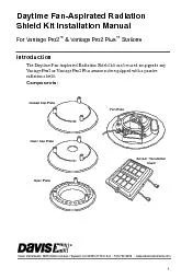
SA 5107329229 wwwdavisnetcom brPage 2br 832 x 314 Screws 3 832 x 12 Screws 3 Threaded Spacers 3 8 SplitLock Washers 6 8 Flat Washers 6 12 Cable Ties 2 brPage 3br brPage 4br Twist to Open brPage 5br Cable Clamp TemperatureHumidity Sensor brPage 6br ID: 58216
Download Pdf The PPT/PDF document "Closed Cap Plate Open Cap Plate Open Pla..." is the property of its rightful owner. Permission is granted to download and print the materials on this web site for personal, non-commercial use only, and to display it on your personal computer provided you do not modify the materials and that you retain all copyright notices contained in the materials. By downloading content from our website, you accept the terms of this agreement.


2 Tools NeededYou may need some or all of the following tools to complete the upgrade: A medium Phillips-head screwdriverOther tools as required to remove and re-mount the sensor suitePrepare to Install Your FanIf you have a console, you should put it in Setup Mode. This prevents the data via the WeatherLink software. See the WeatherLink Online Help for more To put your console in Setup Mode, press and hold the DONE key and then Note: If the console acquires erroneous data during the upgrade, see your console manual Take down the sensor suite (3) (3) (3) #8 Split-Lock Washers (6)Plastic Spacers (2)#8 Flat Washers (6) 3 To disassemble the sensor suite:1.Open the transmitter shelter cover.2.Disconnect the solar panel wire from the cover.3.Remove the foam insert from 4.Disconnect the anemometer cable (labeled WIND) and the 6.You can now remove the sensor suite from its mounted position. Move it to Note: We recommend using a workbench or table to perform the following procedures.1.Remove the rain collector cone from cone counter-clockwise. When the cones latches line up with openings in the base, you can lift the cone off. Tip: Lift off cover, 4 2.Remove the three 8-32 x 4together. Save these three screws model of Vantage Pro2. See below if your temperature/humidity sensor is installed in a different positionmay be mounted on a different plate. In any reinstall as directed below.1.Locate the plate at the top of the radiation Temperature/WasherWasher Temperature/ 5 2.Remove the three screws, flat washer, and cable clamp securing the and flat washer for use later.3.Remove the two screws holding the insulating disk attached on the 4.Reinstall the sensor facing 5.Replace the radiation plate Note: You do not need to use a cable clamp on the sensor cable when mounted on this Temperature/Humidity sensor has been mounted correctly in the radiation plating stack, the existing disks have to be re-organized and assembled with 1.Build the lower section of the new radiation shield by stacking six plates; in this order, from the bottom up:1: The original bottom plate. 2: The disassembled original top plate (with the inslating disc removed).3: The plate containing the temperature/humidity sensor.4 & 5: The two open plates on top of the two bottom plates. 6: The third open plate (supplied with the fan-aspirated kit). Temperature/ Flat Washers (2)Plastic Spacers (2) 6 Note: When stacking plates, make sure their screw standoffs line up with each other. 2.Run the temperature/humidity cable up through the center of the three 3.Set aside the re-assembled radiation shielding and find the fan plate motor assembly.4.Attach the three threaded spacers to the fan plate using the three #8-32 x #8 Flat Washer#8 Split-Lock Washer 7 5.Detach the fan 6.Place the fan 7.Bring the temperature/ Fan PlateFan PlugPower CableAssembly Fan MotorAssembly Temperature/HumidityCableLift Fan Motor upand set aside 8 8.Place one of the 4counter-clockwise from a threaded spacer, making through the standoff in standoff located in the 9.Turn the screw to engage 10.Make sure the other screw standoffs are aligned and the same way.11.Tighten all three screws to 12.Place the fan motor back assembly.13.Unscrew the cable clamp holding the power cable assembly in place.14.Thread the temperature/humidity sensor cable into the cable clamp and 15.Place the cap plates on top (with the closed one on top) of the rest of the radiation shield and line up their standoffs. ScrewStandoff #8 Flat Washer#8 Lock Washer#8-32 x 4" Screws (3) 9 16.Insert one of the 3 1/4below.17.Lower the sensor suite through the standoffs and Turn the screw a few 18.Place a lock washer and 19.Tighten all three screws Radiation Shield Mounting Holes (3) #8 Lock Washers#8 Flat Washers Sensor Suite Base Temperature/Transmitter 10 1.Install the rain collector cone and lock it in place.2.Slide the fan units power cable, the anemometer cable, and the sensor transmitter. Tip:cables are pushed to the left of the access port. Try inserting the three cables through the access port 3.Reconnect the temperature/humidity sensor cable. 4.Close the sensor transmitter cover temporarily without connecting the 5.Test communication between the sensor suite and the console. To test 6.Reinstall the sensor suite in its previous location.7.Open the sensor transmitter cover and discard it.8.Reconnect the WIND (anemometer) cable.10.Find the new sensor transmitter door that came with your fan kit. Connect transmitter board as shown below. Note: This wire is not needed on cabled Vantage Pro2. For cabled systems, you should secure it where it will not interfere with the SIM box. Top PanelWireWire Temperature/ TransmitterTransmitte r ShelterCover 11 11.Connect the wire coming from the bottom solar panel to power cable assembly in the sensor transmitter.12.Reinsert the foam into the cable access port in the sensor transmitter.13.Close the sensor transmitter.14.Use cable ties to secure cables.15.Make sure the fan blades are rotating by directing the transmitter cover to You should hear a slight whir if the fan is running. Tip:Make sure to take the console out of Setup Mode. Refer to your Vantage Pro2 Console Manual for Secure cables so they will not whip in the wind.Secure cables to metal poles by using a cable tie or Place clips or ties approximately every 3 to 5 feet If needed, additional cable ties, cable tie mounts, Note: Do not use metal staples or a staple gun to secure cables. Metal staplesespecially Keep the surfaces of the shield and solar panel clean, since they are less effective when dirty. Remove dust from the solar panel and radiation shield Remove any debris obstructing air flow through the radiation shield such as Do not spray the sensor suite with insecticides of any kind. Some We recommend cleaning out any debris that may have accumulated inside the radiation shield and replacing the motor (# 7758) on an as-needed basis. The 1.Remove your fan-aspirated sensor suite and place on a stable work surface.2.Check to see if the fan motor is still working. If it is not running, replace 3.Disassemble the radiation shield.4.Remove any debris lodged inside the unit.5.Clean the surfaces of the radiation shield with a damp cloth. Cable Tie Securing Cables Daytime Fan-Aspirated Radiation Shield, #7747 7395.236 Rev. D, 2/25/19Vantage Pro and Vantage Pro2© Davis Instruments Corp. 2019. All rights reserved. 3465 Diablo Avenue, Hayward, CA 94545-2778 U.S.A.510-732-9229 Fax: 510-732-9188 ® info@davisinstruments.com www.davisinstruments.co m FCC Part 15 Class B Registration Warningthe FCC Rules. These limits are designed to provide reasonable protection against harmful interference in a residen-tial installation. This equipment generates, uses, and can radiate radio frequency energy and, if not installed and used However, there is no guarantee that interference will not occur in a particular installation. If this equipment does cause harmful interference to radio or television reception, which can be determined by turning the equipment on and off, the Reorient or relocate the receiving antenna.Increase the separation between the equipment and receiver.Connect the equipment into an outlet on a circuit different from that to which the receiver is connected.Consult the dealer or an experienced radio/TV technician for help. Tested to comply 6.Reassemble the radiation shield.7.Re-install the sensor suite in its previous location.Shield, please contact Davis Technical Support. Well be glad to help. Note: Please do not return items to the factory for repair without prior authorization.Onlinewww.davisinstruments.comSee the Weather Support section for copies of user E-mailsupport@davisinstruments.comTelephoneMonday - Friday, 7:00 a.m. - 5:30 p.m. Pacific Time. 1 For Vantage Pro2 & Vantage Pro2 PlusVantage Pro2 or Vantage Pro2 Plus sensor suite equipped with a passive Sensor Transmitter