

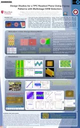
BAzmoun BNL March 7 2017 Inspecting Somcis PCB zigzag using microscope SECTION 1 SECTION 2 SECTION 3 SECTION 4 SECTION 5 Inspected 5 different regions of PCB to gather statistics for the ID: 757413
Download Presentation The PPT/PDF document "Somacis Zigzag PCB #1 QA Report" is the property of its rightful owner. Permission is granted to download and print the materials on this web site for personal, non-commercial use only, and to display it on your personal computer provided you do not modify the materials and that you retain all copyright notices contained in the materials. By downloading content from our website, you accept the terms of this agreement.


Slide1
Somacis Zigzag PCB #1 QA Report
B.Azmoun
, BNL
March 7, 2017Slide2
Inspecting Somcis PCB zigzag using microscope
SECTION 1
SECTION 2
SECTION 3
SECTION 4
SECTION 5
Inspected 5 different regions of PCB to gather statistics for the
fabricated ZZ
pattern
2Slide3
Method
Length calibration of microscope traced to certified standard
Measured pad pitch=2.001mm
Design=2.000mm
Measured zigzag period =586um
Design=587um
Since pad pitch and ZZ period are reproduced very accurately, these may be used as a reference for the measurement of
other, smaller scale features
PCB ZZ period used here as length reference scale for high precision length measurement at the 100 micron level
3
Trace width
Gap width
Gap width-prime
SCALE
MeasurementSlide4
Statistics
(um)
Trace width
Trace width
near Trough
Gap width
Gap width
near Tip
Gap width prime
tip to tip dist.
Section1
148
158.4
84.5
87.4
557.7
350.9
139.3
154.1
81.8
88.8
569.3
349.5
84.7
87.5
84.9
84.9
84 1143.7156.384.087.2563.5350.2Section Avg.Section2141.8146.585.185.1567.9355.3 142.1154.482.285.1576.6362.6 140.7 86.189.4 141.8 83.6 2141.6150.584.386.5572.3359.0Section Avg.Section3142.2150.786.579.3549335.5 138.5153.880.783.8553.4331.1 141.8148.377.889.4 83.8 3140.8150.982.284.2551.2333.3Section Avg.Section4139.3160.680.584.8559.2344.2 141.3156.679.381.8557.8344.2 141.8 83.1 142.9 79.1 80.5 4141.3158.680.583.3558.5344.2Section Avg.Section5137.2149.283.889.8567.9364.6 136.915089.690.2570.8360.2 136.4 87.9 135.6 87.5 86.9 5136.5149.687.190.0569.4362.4Section Avg.Overall Avg.140.8153.283.686.2563.0349.8
4Slide5
Trends
There appear to be no position dependent trends for the measured attributes of the PCB (
ie
, curves are flat)5Slide6
Summary of Results
4 Defining Parameters of Zigzag pattern
DESIGN
PCB (Avg
.
of
Measurements)
Pad pitch (p)
2.000
2.001
mm
zigzag pitch (d)
0.587
0.586
mm
gap (g)
0.075
0.084
mm
trace width (s)
0.155
0.141
mm
Resultant
Zizag
characteristics
DESIGN
Calculated attributes based
upon measurement of 4
param
.
Directly measured attributes
zigzag characterisitic angle
6.604
6.442
?
deg.g'0.6520.7450.563mms'1.3481.2551.437mmStrip Overlap1.8821.8531.650mmStrip Offset-0.534-0.598-0.213mmTip-to-Tip Dist.0.1180.1470.350mmStrip Overlap / Pitch94.192.782.5%Gap / Pitch3.84.24.2%Electrode Area / Tot. PCB Active Area67.462.7?%The reason that the values in the 2nd column differ from the corresponding quantities in the 3rd column is due to deviations of the PCB pattern from a true zigzag geometry(See next slide)6Slide7
Distortions in PCB pattern
7
We’ve identified several distortions in the
features of the PCB electrodes which result in a pattern that deviates from a strict zigzag geometryOver-etched tipsOver-etched trace width (& Trace width waist)
Under-etched troughs
Critical items:The over-etched tips may substantially diminish the performance of the PCB (vis-a-vis reduced charge sharing)
Gaps larger than the design spec. and trace widths narrower than the design spec. will also impact the performance by reducing the amount of copper conductor covering the active area (vis-a-vis larger field distortions near pads)
Minor items:
The trace waist is a small artifact that likely has little impact on the overall design, therefore a waist at the level shown here is tolerable.
The under-etched troughs, though significant in scale, likely have a small impact on the performance and therefore this distortion is tolerable at the levels shown here.
Eroded
Tips
Rounded
Troughs
Slight
Waist
140.8um
153.2um
118um (94% overlap)
350um (83% overlap)
563um
745um
Tip-to Tip dist.