
5000001000000150000020000002500000927119693Buffer size KBOffchip memory accessesinput image cube28input image cube52input image cube76Figure 1 BBCurves of a accelerator Moreover all prior work allo ID: 867096
Download Pdf The PPT/PDF document "ABSTRACTAs the number of onchip accelera..." is the property of its rightful owner. Permission is granted to download and print the materials on this web site for personal, non-commercial use only, and to display it on your personal computer provided you do not modify the materials and that you retain all copyright notices contained in the materials. By downloading content from our website, you accept the terms of this agreement.


1 ABSTRACTAs the number of on-chip acceler
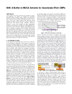
ABSTRACTAs the number of on-chip accelerators grows rapidly to improve power-efficiency, the buffer size required by accelerators drastically increases. Existing solutions allow the accelerators to share a common pool of buffers or/and allocate buffers in cache. But no prior work considers global buffer allocation among multiple accelerators, where each has a range of buffer size requirements with different buffer utilization efficiencies. Moreover, no prior work considers the space fragmentation problem in a shared buffer, especially when allocating buffers in a non-uniform cache architecture (NUCA) with distributed cache banks. In this paper we propose a Buffer-in-NUCA (BiN) scheme with the following contributions: (1) a dynamic interval-based global allocation method to assign spaces to accelerators that can best utilize the additional buffer space, and (2) a flexible paged allocation method to limit the impact of buffer fragmentation, with 500,0001,000,0001,500,0002,000,0002,500,000927119693Buffer size (KB)Off-chip memory accesses input image: cube(28) input image: cube(52) input image: cube(76)Figure 1. BB-Curves of a accelerator. Moreover, all prior work allocates a contiguous space to each buffer to simplify buffer access, since the address of a buffer block is calculated only as a relative position with respect to the buffer starting address [5][6]. This may lead to space fragmentation when requested buffers have unpredictable space demand and come in dynamically, which potentially reduces the usable buffer space. As shown in Figure 2, at Cycle 1K, there is 10KB available space. But since this space is not contiguous, Buffer3 cannot be allocated. In modern CMPs, the last-level cache is typically designed as a NUCA [10][11][12], which complicates buffer allocations in cache. In addition to the buffer size, the distance of the cache bank Shared buffer space: 15KB5KB, 1K cycles duration Buffer25KB, 2K cycles duration Buffer310KB, 2K cycles durationCycle 0: Buffer1Cycle 100: Buffer1 Buffer2 Buffer3 Buffer1 Figure 2. Buffer space fragmenIn this paper we propose a Buffer-in-NUCA (BiN) scheme to dynamically allocate buffers of competing accelerators in NUCA. The contributions of BiN are as follows: (1) a dynamic interval-based global allocation method to assign spaces to accelerators that can best utilize the additional buffer space, and (2) a flexible paged buffer allocation method to limit the impact of buffer fragmentation, with only a small page table at each accelerator. To the best of our knowledge, BiN is the first work to offer a cost-effective solution to accelerator buffer allocations in NUCA, with full consideration of both global buffer allocation and buffer space fragmentation. BiN ARCHITECTURE Overall Infrastructure We construct BiN upon the AXR-CMP [3]a hardware-managed accelerator-rich CMP. Figure 3(a) shows the overall architecture of AXR-CMP with BiN integrated, which is composed of cores (with private L1 caches), accelerators, the accelerator and BiN (ABM), NUCA (shared L2 cache) banks, and NoC routers. The off-chip memory controllers (not shown) are attached to the routers on the four corners. An accelerator node includes a DMA-controller and a small storage space to receive the control structures from the calling threads. ABM manages accelerator sharing (the same functionality as that of the GAM in [3]) and allocates buffers in NUCA (new contribution of this work). Figure 3(b) shows the communications between a core, ABM, an accelerator and NUCA. The numbered arrows show the order of steps taken during a single accelerator invocation by a core. Buffer allocation (Step 2) is described in the following subsections. C CoreL2 BankRouterAcceleratorAccelerator Manager ABM Accelerator (1)(2)(3)(5) (6) (7)(1) The core sends the accelerator and buffer allocation request with the BB-Curve to ABM.(2) ABM performs buffer allocation in NUCA and acknowledges the core.(3) The core sends the control structure to the accelerator.(4) The accelerator starts working with its allocated buffer.(5) The accelerator signals to the core when it finishes.(6) The core sends the free-resource message to ABM.(7) ABM frees the accelerator and buffer in NUCA.(2) NUCA(L2 Cache Banks)Figure 3. (a) Overall architecture of AXR-CMP with BiN. (b) Communications between core, ABM, and accelerator. Dynamic Interval-based Global (DIG) Buffer Allocation In BiN, the space allocated to a particular buffer is dynamically determined at runtime. To avoid greedily allocating buffer space for each buffer allocation request, we propose a interval-based global (DIG) buffer allocation scheme. The key point is that ABM will collect the buffer allocation requests in a short fixed-time interval and then perform the global allocation for the collected buffer allocation requests to achieve short-time global optimality. By keeping the interval appropriately short, we limit the impact on performance of idle waiting in the interval. In this work, unless otherwise specified, we set the interval to be 10K cycles. Moreover, to avoid having too many accumulated buffer allocation requests, once up to eight buffer requests are collected, the DIG allocation will be immediately triggered. Given the batch of buffer allocation requests with a set of points in the BB-Curve of request as {() | 0 } (in increasing order of buffer size, where is the number of points in the BB-Curve of request and are the bandwidth requirement and buffer size of the th point of the BB-Curve of request respectively), the algorithm first allocates the minimum buffer size for each request and tries the paged allocation (detailed in Sectio
2 n 2.3) to see whether this allocation is to see whether this allocation is")
n 2.3) to see whether this allocation is valid. If so, it then checks the next point of each curve, and selects the one with the maximum - b - s), i.e., the request that gives the maximum reduction of bandwidth with unit increase of buffer size. Again, the paged allocation is tried to validate this new allocation. This process will go on, until the next point of each BB-Curve makes the resulting allocation not valid. An example of this scheme is shown in Figure 4. To save the computation of the DIG allocation, - b - s) (buffer utilization efficiency) is pre-computed, so that the curves sent to ABM are actually{(( - ) | 0 }, where = 0, s 1010(,) 1111(,)1212(,)0404(,)0000(,)0101(,)0202(,) 01000100 02010201 11101110 12111211 0100111001001110()()()()bbbb sss 1110020111100201()()()()bbbb sss 0201121112110201()() sss Figure 4. An example of the DIG buffer allocation scheme. Once the allocation decision is made, ABM follows the paged allocation solution to allocate the buffers in NUCA. As in BiC [6], each L2 cache line has a bit to indicate if it is allocated to a buffer. The L1 caches who share the L2 cache block in an allocated cache line will be invalidated and a dirty evicted L2 cache block will be written back to the main memory. If the DIG allocation fails, ABM will leave out the last request and invoke the DIG allocation again on the reduced set of requests. To guarantee liveness, the removed requests are put in an outstanding queue. Once a buffer- free event happens, ABM will allocate them. Otherwise, they will be allocated with the requests accumulated in the next interval (as the earliest requests in that interval). Note that the DIG allocation uses overall throughput other than fairness as the optimization target. However, our evaluation results about the overall runtime of the competing accelerators indicate that fairness is not compromised by the DIG allocation. Moreover, if Quality-of-Service (QoS) is critical for certain requests, we can easily support priority-based reservation of requests with QoS requirements first before applying DIG for the rest of the requests. To achieve global optimization when new requests come in, one may suggest that we should resize some buffers that have been allocated. This either requires that the calling thread prepare a large control structure covering all the possible buffer sizes and the transition operations (around 20~30KB, compared to a 1KB structure for single buffer size), or requires a time-consuming interruption to the calling thread to prepare a new control structure to send to the accelerator on the fly (which typically takes 350K cycles in our evaluated system including context switching). Additionally, the logic describing the transition to an arbitrary larger buffer size is required in accelerators to assure correctness of computation. Furthermore, the decision-making concerning which existing buffer(s) to shrink also takes time and additional resources. Given these overheads, in this work we do not employ any preemption scheme to resize allocated buffers. Flexible Paged Buffer Allocation In BiN, we compose non-contiguous spaces to satisfy the buffer requests. We propose that once a buffer is allocated, the accelerator will use a small local page table to translate buffer addresses into absolute addresses that can be found in NUCA. The key point to achieving this is to set the page granularity for each buffer according to the buffer size; i.e., a larger buffer may have a larger page size so that the total number of pages for this buffer is still a fixed number (32 in our evaluated system). The allowed page size is always a power of 2 to simplify translation. In our evaluated system it ranges from 4KB to half of the L2 cache bank size (32KB). A page must start at an address that is a multiple of the min-page and should not span cache banks. Since all of the buffer allocation and free operations are performed by ABM, it locally keeps the information about the current contiguous buffer spaces of each cache bank. To allocate a buffer with size , ABM uses the smallest page that is no smaller than /32 to try the allocation, starting from the cache bank nearest to this accelerator, to the farthest cache bank. The amount of cache lines that can be used in each cache bank will be discussed in Section 2.4. To try the allocation of a set of buffers, ABM processes the buffers in a decreasing order of the buffer size, since a larger buffer may be more difficult to fit. If any buffer in this set fails to allocate, the paged allocation for this set fails. An example of the flexible paged buffer allocation is shown in Figure 5, where the min-page is 1 way of an 8-way set-associative cache bank. Figure 5. An example of the flexible paged buffer allocation. To reduce the page fragments, we allow the last page (source of page fragments) of a buffer to be smaller than the other pages of this buffer, since this does not affect the page table lookup. For example, in Figure 5, the last page of Accelerator0 is only half the size of its other pages. Therefore, the max page fragment for any buffer is smaller than the min-page. Note that the page fragments do not waste capacity since the cache lines in these fragments will remain as cache blocks and be used by the cache. For example, in Figure 5, the shaded blocks denote the page fragments. Then Sets 2 and 3 of Cache bank 0 actually have five cache lines. In this work we assume a static NUCA design (statically-mapped addresses to banks). Since the buffers are allocated on-demand, the boundary between the cache and accelerator buffers is floating. When BiN allocates buffers in the cache, it could easily co
3 nsume all or most of the cache space to
nsume all or most of the cache space to maximize accelerator gains. To limit the impact on cache performance, we impose an upper bound on the total buffer size that can be allocated. In our implementation where each cache bank is 8-way set-associative, BiN may vary the upper bound from 1/8 to 7/8 of the NUCA size with a 1/8 increment at each step. The upper bound can be controlled by existing cache partitioning schemes (e.g. [13]) where the BiN upper bound is simply one of the partitions competing for space. The accelerators BB-Curves collected in each partitioning interval can be used to estimate the potential variation of off-chip access counts when making partition decisions. BiN can definitely benefit from dynamic upper bound tuning through smart cache partitioning, but our experimental results show that an upper bound set to half of the NUCA size achieves the best or close to the best performance for most of our evaluated benchmarks. Since the focus of this paper is to show the gain of the DIG buffer allocation and the flexible paged buffer allocation over the prior work, we always set the upper bound to be half of the NUCA size unless otherwise declared, in order to make fair comparisons. To avoid creating high contention in a particular cache bank, the upper bound is uniformly distributed to each cache bank; i.e., if the upper bound is half of the NUCA size, then in each cache bank at most half of the cache ways can be allocated as buffers. If high contention still occurs in some cache banks, we use the page re-coloring scheme [12] to remap the OS pages originally mapped to the cache banks to other underutilized banks in order to reduce contention. Other cache bank utilization balancing techniques (such as [10]) can also be used. We would like to emphasize that BiN is orthogonal to and compatible with most state-of-the-art NUCA management schemes since BiN only considers cache bank adjacency while allocating buffer pages in NUCA. Hardware Overhead The system evaluated in this paper is based on a heterogeneous multi-core system consisting of a mix of cores and accelerators as shown in Figure 2(a). The hardware overhead introduced by BiN on this system is mainly in ABM (buffer allocation) and the accelerators (look-up of buffer page locations in NUCA). The block diagram of ABMs buffer allocation module is shown in Figure 6(a). The SRAM table to store the contiguous spaces information for each cache bank is 7-entry. This is because there can be at most 7 contiguous spaces in a 64KB cache bank with a min-page of 4KB, as shown in Figure 6(b). Each entry has 10 bits for the starting block address and 4 bits for the space length in terms of min-page. There are also 8 SRAM tables to store the BB-Curves of the buffer requests (DIG scheme processes at most 8 requests in a batch). We limit BB-Curves to have at most 8 points. Each point uses 2B for the buffer size and 3B for the buffer utilization efficiency. Thus, the total storage overhead is 768B. According to the Synopsys Design Compiler (SAED library, 32nm), the buffer allocation logic has an area of 9,725um under a cycle time of 0.5ns, and the storage area is 3,282um based on Cacti [14] (32nm). Thus, the total area of the buffer allocation module is less than 0.001% for a medium size 1cm chip. An average latency of 0.6us (1.2K clock cycles at 2GHz) is required to perform the buffer allocations. The initial 10K (waiting time in the DIG allocation) + 1.2K cycles of allocation time is only 1% of the typical accelerator runtime (in order of million cycles). Starting blockLengthBuffer size (1)(1)ijijijij Buffer usage efficiency Head pointer 8 entriesContiguous spaces in bank 0Contiguous spaces in bank 31BB-Curve of request 0 7 entries BB-Curve of request 7Head pointer Buffer Allocation Logic Cache banks Allocation / FreeAcknowledge to allocation / Free Update on allocation / free events Way 0 Way 1 Way 2 Way 3 Way 4 Way 5 Way 6 Way 74KB (min-page) 64KB Pages used Cache way retained for cache(b) BiN upper bound: 7/8Figure 6. (a) The buffer allocation module in ABM. (b) Worst-case buffer fragmentation in a cache bank. Figure 7. Block addresses generation with the page table. Figure 7 depicts the local page table of the accelerator and the mechanism to generate the block addresses in NUCA. Since we have 32 banks (5-bit bank ID) and each bank has 1024 blocks (10-bit block ID), each table entry is 15-bit and the page table is 64B. This table has an area of 373um based on Cacti [14], which is less than 1% of the area of our evaluated smallest accelerator : 496,908um). The table access latency is 0.14ns. Since the clock cycle of the evaluated accelerators is 2ns, this latency can easily fit in the pipeline of block address generation. Note that the 15-bit adder in Figure 7 also exists in a shared buffer design with contiguous space allocation. This is not an overhead of BiN. BiN does not introduce any more micro-architectural complexity to the L2 cache controller than BiC [6] does. For buffer allocation in a cache bank, BiN uses the same way-oriented scheme as BiC (it uses cache lines uniformly from one way, and then uses the next). Once the buffers are allocated, as far as the L2 cache controller is concerned, there is no difference between BiN and BiC. Moreover, the overhead of the cache partition scheme and the cache-bank-utilization balancing scheme are not considered as the overhead of BiN, since BiN are orthogonal to these techniques. EVALUATION METHODOLOGY Simulation Infrastructure We extended the full-system cycle-accurate Simics [15] and GEMS [16] simulator to support accelerators and ABM as Simics modules. We also modified Ruby ins
4 ide GEMS to support the buffer operation
ide GEMS to support the buffer operations in NUCA, such as buffer allocation, free, access, and data transfer from/to global memory space. Table 1 shows our simulated system configuration. Table 1. System configuration of Simics/GEMS simulation Core 4 Ultra-SPARC III-i cores @ 2GHz L1 data & instruction cache 32KB for each core, 4-way set-associative, 64B cache block, 3-cycle access latency, pseudo-LRU, MESI directory coherence by L2 cache L2 cache 2MB, 32 banks, each bank is 64KB, 8-way set-associative, 64B cache block, 6-cycle access latency, pseudo-LRU 4X8 mesh, XY routing, wormhole switching, 3-cycle router latency, 1-cycle link latency Main memory 4GB, 1000-cycle access latency For this work we chose applications from one domain (medical imaging) to accelerate, since accelerator-rich architectures (such as AXR-CMP) are most suitable for domain-specific computing [17]. We chose the medical imagiit consists of applications that are both compute- and memory-intensive, and the highly regular computation of the domain makes it an ideal target for hardware acceleration. Furthermore, improved performance in medical imaging has a tremendous potential to transform health care. The chosen applications are: denoisedeblursegmentationregistration. These applications are explained in detail in [9] and form a medical imaging pipeline. We use the methodology of [3] to extract the computation-intensive tasks of these applications as accelerators and obtain their cycle-accurate modules. We then plug these modules into our simulator. Each of these accelerators has at least 4 copies on the chip to allow threads calling the same type of accelerator to run simultaneously. All of the accelerators work at a frequency of 500MHz. The non-computation-intensive and control tasks of these medical imaging applications and the Solaris-10 OS are running on the general-purpose cores. In Section 4.4, to demonstrate the impact on the cache, we also discuss running SPEC CPU2006 benchmarks on the cores when buffers are dynamically allocated in the cache for the accelerators. We compare BiN to the following representative schemes from prior work. All are evaluated under the same area constraint. To make a fair comparison, we set a fixed upper bound of BiN as half of the NUCA size when comparing to the prior work. We will discuss the impact of dynamic upper bound tuning in Section 4.4. Accelerator Store (AS) [5]. In AS the shared buffer and NUCA are two separate units. We set the 32-bank NUCA size as 1MB (since we use an upper bound as half of the NUCA size in BiN). Because buffers in cache have some area overhead compared to separate buffers, we set the capacity of the shared buffer in AS as 1.32MB (32% larger than the maximum buffer size in BiN under the same area constraint) based on Cacti [14]. We also partition the shared buffer into 32 banks to increase the buffer access ports and these banks are distributed to the 32 NoC nodes. BiC dynamically allocates contiguous cache space to a buffer. Here we set an upper bound for BiC by limiting buffer allocation to at most half of each cache bank. To allow a buffer to span multiple cache banks, the end of the BiC space in one cache bank is considered to be contiguous to the beginning of the BiC space in the next cache bank. The system configurations of BiN and BiC are the same except that the DIG allocation and the flexible paged allocation are not available in BiC. This scheme is used to show that simply allocating buffers in NUCA will result in space fragmentation and underutilization. We use the off-line compiler analysis in [8] to generate the desired buffer space of a set of potential input sizes for both AS and BiC to achieve their best performance. In addition, to demonstrate the innovations of BiN step by step, we also construct the following schemes. 1) BiN-Paged. It only uses the proposed flexible paged allocation scheme. 2)BiN-Dyn. Based on BiN-Paged, it also performs dynamic allocation without consideration of near future buffer requests; i.e., it just responds to a buffer allocation request immediately by greedily satisfying the request with the current available spaces. Thus, a new buffer allocation request may not be satisfied since a preceding buffer has consumed most of the spaceeven if the new requesting accelerator can use the space more efficiently. 3) . This is the entire proposed BiN scheme as described in Section 2. RESULTS We conduct experiments for different degrees of buffer pressure by varying the number of medical imaging pipelines that we run in parallel (1, 2, and 4 pipelines). Each pipeline consists of one thread sequentially executing the four medical imaging applications on a different set of imaging data (i.e., no data dependencies between pipelines), where the image sizes also vary. Our benchmark naming convention indicates both the number of concurrent pipelines and the image size for that particular run. For example, benchmark 4P-28 means that there are 4 copies of the pipeline running in parallel and the input to each is a unique image that is 28x28x28 pixels. The mix label indicates that the various pipelines in the benchmark have randomly selected input image sizes. Benchmarks from 1P-28 to 4P-100 feature pipelines that are running with the same input image sizes. Thus there is no buffer fragmentation problem. These benchmarks are mainly used to demonstrate the gain of the DIG allocation. The 4P-mix benchmarks are used to demonstrate the gain from both the flexible paged allocation and the DIG allocation, since computation over varied image sizes exhibits variation in the buffer demand and duration of buffer use, which in tu
5 rn results in fragmentation. This may de
rn results in fragmentation. This may delay the buffer allocation in AS and BiCeven when there are enough non-contiguous buffer spaces. Impact of DIG Buffer Allocation Figure 8 and Figure 9 show the comparison results of runtime and off-chip memory access counts. All of the results in Section 4.1 to 4.3 are normalized to that of AS (Accelerator Store). In the first 12 benchmarks, since there is no buffer fragmentation, AS, BiC, and BiN-Paged behave similarly (the impact of buffer-to-accelerator distance will be discussed in Section 4.2). 0.00.20.40.60.81.01.21.4P-21P-1P-1P-1002P-P-74P-28P-52-104P-mimixNormalized Run tim e BiC BiN-Paged BiN-Dyn BiN-Fullresults of runtime. By greedily satisfying the buffer requests with currently available resources, BiN-Dyn outperforms AS, BiC, and BiN-Paged in 1P cases and 2P/4P cases with small inputs, because the shared space can accommodate these small buffers even if they are greedily satisfied. This gain can also be confirmed by the bandwidth reduction in these cases (shown in Figure 9). However, in the cases where greedily satisfying the first buffer requests will severely reduce the available space for subsequent requests that may more efficiently use the buffer space, BiN-Dyn behaves considerably worse compared to the first three schemes, as can be seen in the 2P/4P cases with large input sizes. Interestingly, the off-chip memory access counts do not increase correspondingly. The reason is that, when BiN-Dyn allocates a large buffer for the initial requests, it will delay subsequent requests from accelerators with large input sizes. Eventually these subsequent requests will be assigned to a large buffer (for reducing off-chip bandwidth), but their execution is serialized and thus the performance is impacted. Therefore, a reduction of the total off-chip memory accesses may not necessarily result in an increase in performance. 0.00.20.40.60.81.01.21P-104P-524P-764P-1004P-m4P-m4P-miNormalized Off-chip me m access counts BiC BiN-Paged BiN-Dyn BiN-Full results of off-chip memory accesses. BiN-Full consistently outperforms the other schemes because of the DIG allocation (and also the flexible paged allocation in the 4P-mix cases). The only exception is in 4P-mix3, where the 1.32X larger capacity of AS is just large enough to accommodate all buffer requests; whereas BiN-Full needs to allocate a smaller buffer size to the accelerator that has the smallest buffer utilization efficiency. But it still outperforms the other three schemes that have the same total capacity. Overall, compared to AS and BiC, BiN-Full reduces the runtime by 32% and 35%, respectively. Impact of Paged Buffer Allocation In the 4P-mix cases where there are buffer fragmentation problems, up to 24%) in 4P-mix{1,4,5,6} by aggregating non-contiguous space to satisfy the parallel buffer requests. In 4P-mix{2,3}, the 1.32X larger capacity of AS can accommodate the buffers even when there is fragmentation. Thus BiN-Paged behaves similar to or even worse than AS. But in both cases, BiN-Paged outperforms BiC, which has the same capacity. Since the first 12 benchmarks do not suffer buffer fragmentation, BiN-Paged improves their runtime by allocating buffers closer to the accelerator. However, the improvement is small. The reason is as follows. The buffer accesses from our evaluated accelerators are mainly reading in large amounts of input data, performing some calculation on the data and then writing the transformed data out to the buffers. These accesses do not have inter-dependencies. They are pipelined so well that buffer access latency is completely hidden. Therefore, as shown in Figure 10, even though BiN-Paged can improve the average buffer access latency by 19%-32%, the runtime gain is only 2%-9%. We expect that accelerators from other domains which may have dependencies among the buffer accesses can obtain more benefit from adjacent buffer allocation. 1P-1P-1P-1P-1002P-2P-2P-2P-1004P-4P-4P-4P-100Avg buffer access latenc y (Normalized toaccelerator store) BiC BiN-PagedFigure 10. Comparison results of buffer access latency. We obtain the dynamic and leakage energy data of NUCA and the main memory through Cacti [14] and McPAT [18], and the power data of the ABM module via the Synopsys Design Compiler. We back-annotate these numbers into our simulator to obtain the energy results. Figure 11 shows the results of the memory subsystem energy consumption. By allocating buffers in cache, BiC, BiN-Paged, BiN-Dyn and BiN-Full consume more energy for each cache/buffer access and also consume more standby leakage than AS, because the buffer and cache are two separate units in AS. Therefore, BiC and BiN-Paged consume more energy than AS. BiN-Dyn can save energy in cases where it can reduce the off-chip memory accesses and runtime. However, in the cases where BiN-Dyn significantly increases the runtime, BiN-Dyn will also have a large energy overhead (more standby energy). By performing DIG and flexible paged buffer allocation, BiN-Full can reduce both the number of off-chip memory accesses and the runtime. When compared to AS, it sees a 12% reduction in energy on average. In cases where the 1.32X capacity of AS can better satisfy buffer requests (4P-mix3), BiN-Full consumes more energy due to more off-chip memory accesses and longer runtime. BiN-Full reduces the energy by 29% on average compared to BiC. 1.81 2.16 1.95 -522P-28-762P-1004P-52mix4P-mix2ix3mix44P-ix5mixNormalized Memor y subsystem energy BiC BiN-Paged BiN-Dyn BiN-Fullmparison of the memory subsystem. Impact on Cache We further evaluate BiNs impact on the cache by running a set of general-purpose applications (SPEC CPU2006 benchmar
6 ks) on the cores concurrently. The goal on the cores concurrently. The goal")
ks) on the cores concurrently. The goal is to quantify the impact of the effective cache capacity reduction due to buffer allocation. dealII obmkhmmermil namdomnet pp ovra p hinxxalancbmk0.800.901.001.101.20 w.o. BiNw. BiN (upper bound: half of NUCA)Normalized runtimeFigure 12. Impact of BiN with a fixed upper bound (half of the NUCA size) on the runtime of SPEC benchmarks. In the previous experiments we use a fixed BiN upper bound which is half of the NUCA size. Thus, we first evaluate the impact on SPEC benchmark runtime when half of the NUCA space is allocated by BiN, as shown in Figure 12. The results are normalized to full cache capacity performance (additional separate buffers are required for the accelerators, which consume more area and energy). In most cases the runtime increase is within 10%, except which has a large working set. For , although a full-capacity NUCA with separate buffers has a remarkably small runtime, it comes with the cost of doubling the on-chip memory subsystem energy and area, and has less flexibility. dealIIgccgobmkhmmermilcnamdomnetppperlpovraysphinxxalancbmk1st bar: 2p-28, 2nd bar: 2p-52, 3rd bar: 2p-76, 4th bar: 2p-100 Cache BiN upper boundPercent of capacity 0.920.940.960.981.021.042p-1002p-2p-2p-1002p-2p-2p-1002p-2p-2p-2p-2p-1002p-1002p-Normalized runtime SPEC Medical imaging pipeline Product Figure 13. (a) Partitions via dynamic upper bound tuning. (b) Runtime compared to a fixed upper bound (half of NUCA). The impact of BiN on the cache can be improved via dynamic upper bound tuning. We consider the upper bound of BiN as one cache partition and the remaining cache as another partition. Then we use the cache partitioning scheme proposed in [13] to dynamically tune the upper bound. We run each SPEC benchmark simultaneously with two medical imaging pipelines for each of the 4 input sizes, respectively. The dynamic tuned BiN upper bounds for each case are shown in Figure 13(a). In most cases an upper bound of half of the NUCA size is selected. In the cases where the SPEC benchmarks can give more space to BiN without considerably impacting the performance, an upper bound of 5/8 of the NUCA size is selected for BiN. For these cases, the runtime of both SPEC benchmarks and the medical imaging pipelines (normalized to the runtime with an upper bound as half of the NUCA size) and the product of the two are shown in Figure 13(b). All of the runtime variations are within the range of 5%, which suggests that impact of the upper bound tuning is limited. CONCLUDING REMARKS In this paper a Buffer-in-NUCA (BiN) scheme is proposed to share accelerator buffers in NUCA for accelerator-rich CMPs. It achieves highly efficient on-chip storage utilization through the use of 1) a dynamic interval-based global buffer allocation method to assign spaces to accelerators that can best utilize the additional buffer space, and 2) a flexible paged buffer allocation method to limit the impact of buffer fragmentation. Experimental results on medical imaging applications show that BiN can significantly improve both performance and energy when compared to two representative schemes from the prior work. To reduce the complexity of buffer allocation, in this paper, BiN only considers cache bank adjacency when allocating buffers and relies on a uniformly distributed upper bound and existing NUCA bank utilization balancing schemes to mitigate the potential cache bank contentions caused by buffer allocation. An interesting extension of BiN will be to consider both bank adjacency and dynamic bank utilization. Note that it is the flexible paged buffer allocation method proposed in this paper that allows the flexible allocation of buffer pages in any cache bank (either more adjacent to the accelerator, or more underutilized, or both). REFERENCES NCES C. Johnson et al. A wire-speed powerTM processor: 2.3ghz 45nm soi with 16 cores and 64 threads. ISSCC 2010. L. Seiler et al. Larrabee: A many-core x86 architecture for visual computing. IEEE Micro, 29(1):1021, 2009. J. Cong et al. AXR-CMP: architecture support in accelerator-rich Workshop on SoC Architecture, Accelerators and Workloads 2011. ITRS 2007 system drivers. http://www.itrs.net/ M. J. Lyonsy et al. The Accelerator Store: a shared memory framework for accelerator-based systems. ACM Architecture and , 8(4):48, 2012. C. F. Fajardo et al. Buffer-Integrated-Cache: a cost-effective SRAM architecture for handheld and embedded platforms. DAC 2011. J. Cong et al. An energy-efficient adaptive hybrid cache. ISLPED 2011. J. Cong et al. Combined loop transformation and hierarchy allocation for data reuse optimization.2011. A. Bui et al. Platform characterization for domain-specific computing. ASPDAC 2012. B. M. Beckmann et al. ASR: adaptive selective replication for CMP MICRO 2006. N. Hardavellas et al. Reactive NUCA: near-optimal block placement ISCA 2009. S. Cho and L. Jin. Managing distributed, shared L2 caches through OS-level page allocation. 2006. 2006. M. Qureshi and Y. Patt. Utility-based cache partitioning: a low-overhead, high-performance, runtime mechanism to partition MICRO 2006. HP Cacti, http://quid.hpl.hp.com:9081/cacti/ P. S. Magnusson et al. Simics: a full system simulation platform. IEEE Computer, 35(2):50-58, 2002. M. M. K. Martin et al. Multifacets general execution-driven multiprocessor simulator toolset. SIGARCH Computer Architecture , 33(4):92-99, 2005. J. Cong et al. Customizable domain-specific computing. IEEE Design and Test of Computers, 28(2):5-15, 2011. S. Li et al. McPAT: an integrated power, area, and timing modeling framework for multicore and manycore architectures. MICRO 2009. (