
2009 2012Cisco All rights reserved This document is Cisco PublicPage 1of 9Data SheetCisco ROSA EM Element Management SystemThe CiscoROSAElement Manager EM is specifically designed to cost effectively ID: 875218
Download Pdf The PPT/PDF document "andor its affiliates" is the property of its rightful owner. Permission is granted to download and print the materials on this web site for personal, non-commercial use only, and to display it on your personal computer provided you do not modify the materials and that you retain all copyright notices contained in the materials. By downloading content from our website, you accept the terms of this agreement.


1 © 2009, 2012 Cisco and/or its affil
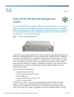
© 2009, 2012 Cisco and/or its affiliates . All rights reserved. This document is Cisco Public. Page 1 of 9 Data Sheet Cisco ROSA EM Element Management System The Cisco ® ROSA ® Element Manager (EM) is specifically designed to cost effectively monitor and control the transmission network of headends, hub sites, HFC outside plants, and transmitter sites. This unit manages the equipment that is co - located at the site where the ROSA EM resides, whether this equipment has an SNMP, serial (RS - 232/422/485) , or contact closure interface . Figure 1. ROSA EM â Element Manage ment System The ROSA EM is a polling engine that actively polls all of the devices that it manages looking for problems. In the event a problem is detected, ROSA EM will send alarm notificat ions to the appropriate personnel via SNMP trap, Email, Pager, or SMS. ROSA EM communicates with the managed devices via proprietary protocols or contact closures, then translates this information to SNMP, which can be passed to a higher level network mana gement system. When ROSA EM is configured to perform backup protection, it will automatically initiate pre - defined backup schemes that reroutes signals, activates, and configures standby devices, all within seconds of a device failure. ROSA EM is fully int egrated on the ROSA Network Management (NMS) and ROSA Video Service Management (VSM) systems. The main functions of the ROSA EM are to : â Automatically backup failed devices â Monitor the health of the transmission network â Act as an SNMP proxy â Send alarm notif ications when a problem occurs â Perform local automation tasks The ROSA EM is a 2 RU high, 19 - inch rack - mount embedded platform that operates without a monitor or keyboard. The operator uses a standard web interface with the ROSA E
2 M via a simple easy - to - use GUI.
M via a simple easy - to - use GUI. Communication to the ROSA EM can be established over any LAN/WAN network that supports Ethernet. In addition, dial - in and dial - out (e.g., ISDN) is supported for cases where only a switched connection is available . © 2009, 2012 Cisco and/or its affiliates . All rights reserved. This document is Cisco Public. Page 2 of 9 Features â Cost - effective solution for management of devices in all locations (large headend to small hubs/OTN) â Manages Cisco IPVS Video Processing Devices and optional third - party equipment via proprietary protocol, SNMP, or contact closures â Translates proprietary protocols to SNMP and pas ses configuration/alarm information to upper level network managers â Highly reliable hardware and software solution (no fans or hard drive) â Easy to use and intuitive Web browser interface â Provides easy integration with multiple client options â Web browser , TNCS, ROSA NMS, Third - party NMS â Open standards based interfaces (SNMP, HTTP, FTP, HMS, DateTime, etc.) â Automatic remote backup and restore to save the entire configuration of the ROSA EM â Seamless integration into currently installed ROSA NMS en VSM systems â Dual temperature probes available as an option â 2 RU, 19 - inch rack - mount chassis System Description ROSA EM supports open standards interfaces, which enable cost - effective integration of equipment into the ROSA EM, as well as cost - effective integrat ion of the ROSA EM into upper - level network managers. Figure 2. ROSA EM â Northbound and Southband Management Interfaces The northbound management interfaces are composed of: â Web browser client interface on the ROSA EM that allows management of network devices as well as viewing real -
3 time status and alarms. â The SNM
time status and alarms. â The SNMP agent in ROSA EM provides a northbound SNMP interface to higher level Network Management Systems (supports TRAPS, GETS and SETS). â Ut ilizes FTP to remotely upgrade ROSA EM software as well as the backup and restoration of ROSA EM configuration data. © 2009, 2012 Cisco and/or its affiliates . All rights reserved. This document is Cisco Public. Page 3 of 9 The southbound management interfaces are designed to communicate with the managed devices and consist of: â Multiple serial ports (RS - 232, RS - 485, RS - 422) â Digital and analog I/O contact closures interface â SNMP Manager â Temperature probes â Network interface card There are four fundamental client options available for the ROSA EM; a Web browser, ROSA VSM client , ROSA NMS client and third party N etwork Management Systems each designed to meet specific needs of the user. ROSA EM can be configured to do as much or as little as required to meet the needs of the technicians and engineers charged with managing the broadband network . Deployment Figure 3. ROSA EM Deployment ROSA EM can be deployed in different applications throu ghout a Video Delivery network : â Origination / Acquisition Main Headend and Regional Headend ⦠Video Processing Device redundancy architecture for Encoders, IRDs, and DCMs. ⦠Audi o/Video Router (SDI) controller. ⦠Protol Gateway for different type s of Video Processing gear s, such as IF Redundancy Switches and Legacy interfaces. â Hub and Transmitter Sites: ⦠Protection of Cisco eQAM devices ⦠Monitoring of Electrical / Optical transport gear ⦠Environmental monitoring over Temperature Sensor and GPIO interfaces © 2009, 2012 Cisco and/or its affiliates . All rights reser
4 ved. This document is Cisco Public. Pa
ved. This document is Cisco Public. Page 4 of 9 Redundancy Controller for Cisco IPVS Video Processing Devices ROSA EM is a key element in the redundancy architecture of Ciscoâs video processing gear in the Acquisition an d Origination Suite. The combination of the Cisco Digital Content Manager (video processor) and the Cisco ROSA control system , provides device level redundancy for many application s at content acquisition ( for example, IRD redundancy) and processing ( for e xample, Encoder redundancy). In certain applications, such as the Cisco Reference Architecture of the D9036 - DCM - Statmux System, ROSA EM guarantees up to c hannel r edundancy . Integrated with the ROSA VSM System and ROSA NMS System ROSA EM integrates where device redundancy is required in the Acquisition and Origination type video processing platform, such as in the Cisco Reference Architecture of the D9036 - DCM - Statmux System. It serves as the Device Redundancy Controller, it gu arantees service uptime , and it is a key element in the Control and Management (M&C) tasks . It operate s and manage s daily activities in linear video channel processing environments, known as Ciscoâ s Acquisition and Origination Suite. Product Specifications Table 1. Product Specifications Specification Value Remote Control and Configuration Ports (*) Ethernet Management Port (Note 1) Number of Ports 2 Connector Type RJ - 45 Physical layer 10/100BaseT LED indication LINE and ACT Dielectric isolation 1.5 kV AC RS - 232 Serial Ports Number of Ports 4 Connector type Male, 9 - pin Sub - D Pin Layout Standard DTE Physical Layer RS - 232 Baud Rate Up to 38.4 kbaud Protocol RCDS, SMC or other ESD Max. 15 kV Performance Criterion B RS - 232 / RS - 485
5 / RS - 422 Serial Ports (Configurable)")
/ RS - 422 Serial Ports (Configurable) Number of Ports 4 Connector type Male, 9 pin Sub - D Pin Layout Configurable (for RCDS or SMC pin layout refer to user guide) Physical Layer RS - 232, RS - 422, RS - 485 Baud Rate Up to 38.4 kbaud Protocol RCDS, SMC or other ESD Max. 15 kV Performance Criterion B Digital Input Ports © 2009, 2012 Cisco and/or its affiliates . All rights reserved. This document is Cisco Public. Page 5 of 9 Number of Ports 108 Connector type Female, 25 pin Sub - D Contacts per port 2 Decision threshold TTL / CMOS Input Voltage Range Max. ± 15V ESD Max. 15 kV Performance Criterion B Galvanic Isolated Digital Input Ports Number of Ports 12 Connector type Female, 25 - pin Sub - D Contacts per port 2 Decision threshold Low: .8V, High:&#x 040; 2V Differential overvoltage protection Max. ± 15V Common mode input voltage Max. 60 V DC or 42 V AC ESD Max. 15 kV Performance Criterion B Dielectric isolation 500 V port to port Relay Outputs Number of Ports 24 Connector type Female, 25 - pin Sub - D Contacts per port 3 (common, normally open, normally closed) Maximum voltage 42 VAC / 60 VDC Maximum load current 1A @ 30 VDC Dielectric isolation 500 V Load Resistive load External Temperature Sensor (Note 2) Number of Ports 2 Analog Inputs Number of Ports 8 Connector type Female, 25 - pin Sub - D Contacts per port 2 Input range 0 to +15 V by default, configurable to 0 to +60 V Type Differential input Resolution 8 - bit (55 mV step with 15 V input range, 250 mV step with 60 V input range) Input impedance � 100 k ï Analog Outputs Number of Ports 2 Connector type Female, 25 - pin Sub - D Contacts per port 2 Output voltage range 0 to
6 +10V Resolution 8 - bit (40 mV step)")
+10V Resolution 8 - bit (40 mV step) Output impedance 1 k ï Craft Interface Number of Ports 1 Connector type Male, 9 - pin Sub - D Pin Layout Standard DTE © 2009, 2012 Cisco and/or its affiliates . All rights reserved. This document is Cisco Public. Page 6 of 9 Physical Layer RS - 232 Baud Rate Up to 38.4 kbaud (default 19.2 kbaud) ESD Keyboard and Mouse Number of Ports 2 Connector type PS/2 Pin Layout Standard PS/2 Physical Layer RS - 232 ESD Max. 15 kV Monitor Number of Ports 1 Connector type DB15H Pin layout VGA Resolution Up to 1024 x 768 (SVGA) (*) Note concerning Safety Extra - Low Voltage (SELV) Circuit Warning Notes : â To avoid electric shock and in order to comply with the productâs regulatory safety compliance certifications: â Do not connect any I/O, signal or communication port to circuits falling beyond the requirements for SELV circuits â Always verify voltage, current and energy levels of connected circuits against SELV requirements (for a full definition of SELV requirements, refer to UL, EN or IEC 60950 standards for limit values). â Ensure that only âDi gital Input Portsâ, Galvanic Isolated Digital Input Portsâ or âRelay Outputsâ are connected to outdoor circuits. Important: â SELV voltage limits for indoor connections are 60 VDC (or peak) or 42.4 VAC RMS. â SELV voltage limits for outdoor connections are lower than those for indoor connections. â Outdoor voltages should be no greater than 15 Vrms, 21.2 Vpk, and 30 VDC under normal operating conditions. â Cabling of outdoor circuits must be shorter than 140 feet or 42 meters. â In all cases it is needed to prote ct outdoor cabling by means of a Primary Surge Protector at the position where the wiring
7 enters the building. â Outdoor ca
enters the building. â Outdoor cabling should be routed away and spaced with adequate clearances from power and lighting conductors. â For installations in the United Sta tes, refer to the appropriate sections in the National Electrical Code (NEC). â For installations in other countries, ensure that the installation complies with the National requirements taking in account the above - mentioned recommendations. â In case a client (simple Web browser, TNCS client, ROSA NMS client or third - party NMS) is used in combination with ROSA EM, it must be possible to perform a successful ping command between ROSA EM and the client in both directions. â Temperature sensors are available as an option. © 2009, 2012 Cisco and/or its affiliates . All rights reserved. This document is Cisco Public. Page 7 of 9 Table 2. Management Interfaces Management Interfaces Number of managed devices depends on license with an absolute maximum of 1000 devices Maximum number of simultaneously connected web browser sessions is 12 Table 3. Environmental Specifications Environmental Specification Value Within specifications +10 ï° C to +45 ï° C / +50 ï° F to +113 ï° F Operating temperature 0 ï° C to + 50 ï° C / +32 ï° F to +122 ï° F Storage temperature - 20 ï° C to + 70 ï° C / - 4 ï° F to +158 ï° F Power Supply AC (Dual Power Supply) Nominal voltage range 2 x 100 â 240 VAC Full voltage range 90 â 264 VAC, 47 â 63 Hz Ripple & Noise Compliant with ETSI ETS 300 - 132 - 1 Maximum power consumption 25 W Power Supply DC Nominal voltage - 48 VDC Ripple & Noise Compliant with ETSI ETS 300 - 132 - 2 Maximum power consumption 25 W Table 4. Mechanical Specifications Mechanical Specifications Value Height 88 mm / 3.5 i
8 n. (2 RU) Width 482 mm / 19 in. De
Width
482 mm / 19 in.
De")
n. (2 RU) Width 482 mm / 19 in. Depth 470 mm / 18.5 in. Weight Approx. 5 kg / 11.02 lbs. Ordering Information Cisco ROSA EM is available for purchase through regular Cisco sales and distribution channels worldwide. To place an order, visit the Cisco Commerce Workspace . Table 5. Ordering Information â Cisco ROSA EM â - Hardware Description Part Number ROSA Element Manager (EM) , 2RU Chassis ROSA - EM ROSA EM Chassis Option â ROSA EM: Chassis - Dual AC Version ROSA - EM - BASE - AC â ROSA EM: Chassis - Single DC Version ROSA - EM - BASE - DC Power Cord Pack â AC PWR CABLE, ARGENTINA, IEC, 10AMP, 2.5m CAB - PWR - DMN - ARG â AC PWR CABLE, AUSTRALIA, IEC, 10AMP, 2.5m CAB - PWR - DMN - AUS â AC PWR CABLE, BRAZIL, 10AMP, 2.5m CAB - PWR - DMN - BRA â AC PWR CABLE, CHINA, IEC, 10AMP, 1.83m CAB - PWR - DMN - CHN © 2009, 2012 Cisco and/or its affiliates . All rights reserved. This document is Cisco Public. Page 8 of 9 â AC PWR CABLE, EUROPE, IEC, 10AMP, 2.5m CAB - PWR - DMN - EU â AC PWR CABLE, ITALY, IEC, 10AMP, 2.5m CAB - PWR - DMN - IT â AC PWR CABLE, JAPAN, IEC, 7AMP, 2.3m CAB - PWR - DMN - JPN â AC PWR CABLE, UK, IEC, 10AMP, 2.5m CAB - PWR - DMN - UK â AC PWR CABLE, US, IEC, 10AMP, 1.83m CAB - PWR - DMN - US Table 6. Ordering Information â ROSA EM â Licenses Description Part Number ROSA EM Software Suite, Licenses and Upgrades ROSA - LIC - EM - UPG EM Feature Pack Licenses â ROSA EM License: Standard Functionality (no Backup support) LROSA - E - STD â ROSA EM License Upgrade: Support of Redundancy Control LROSA - E - STD2RED EM Device Class Count Upgrades â ROSA EM License: Device Class Support - Single Count LR
9 OSA - E - DCL - CT â ROSA EM Licen
OSA - E - DCL - CT â ROSA EM License: Device Class Support - 50 Count Block LROSA - E - DCL - CT50 â ROSA EM License: Device Class Support - 250 Count Block LROSA - E - DCL - CT250 â ROSA EM License: Device Class Support - 500 Count Block LROSA - E - DCL - CT500 â ROSA EM License: Device Class Support - 1K Count Block LROSA - E - DCL - CT1K EM Redundancy Group Device Counts â ROSA EM License: Redundancy Group Dev Count - Single Count LROSA - E - RED - CT â ROSA EM License: Redundancy Group Dev Count - 50 Count Block LROSA - E - RED - CT50 â ROSA EM License: Redundancy Group Dev Count - 250 Cnt Block LROSA - E - RED - CT250 â ROSA EM License: Redundancy Group Dev Count - 500 Cnt Block LROSA - E - RED - CT500 â ROSA EM License: Redundancy Group Dev Count - 1K Cnt Block LROSA - E - RED - CT1K EM Software Upgrade License â ROSA EM: SW Upgrade to 4X LROSA - E - UP - V4X - K9 © 2009, 2012 Cisco and/or its affiliates . All rights reserved. This document is Cisco Public. Page 9 of 9 Service and Support Using the Cisco Lifecycle Services approach, Cisco and its partners provide a broad portfolio of end - to - end services and support that can help increase your networkâs business value and return on investment. This approach defines the minimum set of activities needed, by technology and by network complexity, to help you successfully deploy and operate Cisco technologies and optimize their per formance throughout the lifecycle of your network. For More Information For more information about Cisco ROSA Management and Control Solutions, visit http://www.cisco.com/go/rosa or contact your local Cisco accou nt representative . Printed in USA 95 - 7003710 - 01 Rev H