/
Automated Grid Generation for WAVEWATCH III Automated Grid Generation for WAVEWATCH III

Automated Grid Generation for WAVEWATCH III - PowerPoint Presentation

paige
paige . @paige
Follow
68 views
Uploaded On 2023-09-25

Automated Grid Generation for WAVEWATCH III - PPT Presentation

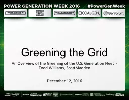
Arun Chawla The WAVEWATCH III Team friends Marine Modeling and Analysis Branch NOAA NWS NCEP EMC NCEPlistWAVEWATCHNOAAgov NCEPlistwavesNOAAgov Outline Covered in this lecture ID: 1021341

grids grid resolution mask grid grids mask resolution land wet data cells iii boundary cell global boundaries sea overlapping

Share:

Link:

Embed:

Download Presentation from below link

Download Presentation The PPT/PDF document "Automated Grid Generation for WAVEWATCH ..." is the property of its rightful owner. Permission is granted to download and print the materials on this web site for personal, non-commercial use only, and to display it on your personal computer provided you do not modify the materials and that you retain all copyright notices contained in the materials. By downloading content from our website, you accept the terms of this agreement.


Presentation Transcript

1. Automated Grid Generation for WAVEWATCH IIIArun ChawlaThe WAVEWATCH III Team + friendsMarine Modeling and Analysis BranchNOAA / NWS / NCEP / EMCNCEP.list.WAVEWATCH@NOAA.govNCEP.list.waves@NOAA.gov

2. OutlineCovered in this lecture:The grids necessary for running WAVEWATCH III codesThe reference data used for creating the gridsThe different modules of a grid generation software to develop the gridsAdditional changes needed to the grids to allow two – way communications between grids for multi-grid WAVEWATCH III

3. MotivationWAVEWATCH III requires 3 grids (1 necessary and two optional) A bathymetry grid (necessary)A land –sea mask grid (optional in WW III v 2.22, needed in multi-grid version of WW III)Obstruction grid to account for energy decay due to sub-grid blocking (optional)Development of these grids can be a fairly arduous task. This is specially true for multi-grid version of WW III where grid consistency across overlapping grids is necessary for accurate two – way coupling.To facilitate this we developed a set of algorithms that can automatically create accurate grids with minimal input from the user.The necessary tools have been developed using MATLAB.

4. MODULESStep 1: Build a bathymetric grid from a high resolution base bathymetryStep 2: Create an appropriate land / sea mask to accurately depict coast linesStep 3: Mask out un-necessary water bodiesStep 4: Generate obstruction grids for unresolved islandsStep 5: Identify nodes for exchanging boundary information (multiple-grid only)

5. Reference DataTwo types of high resolution reference data availableA global high resolution bathymetry data setETOPO2 from the National Geophysical Data Center2’ arc length global relief bathymetry data setETOPO1 from the National Geophysical Data Center1’ arc length global relief bathymetry data setA global shoreline database in the form of polygons (GSHHS - Global Self-consistent Hierarchical High-resolution Shoreline)Algorithms will be designed to meld the high resolution bathymetry with the shoreline database to develop the optimum grids.

6. SubroutinesA grid generation routineGenerates a grid from base bathymetric data set. We use global ETOPO2/ETOPO1 bathymetry netcdf files. (NOTE: To use this routine your matlab should be able to handle netcdf files. Capability is available as open source)A boundary extraction routineExtracts a subset of boundaries from a global set of polygon boundaries (GSHHS)A land-mask routineBlends the bathymetric data with the coastal boundaries to develop an accurate land-sea maskA water body routineGroups the wet cells into different water bodies (each having a unique id)A sub-grid obstruction routineDevelops sub-grid obstruction matrices in x and y direction for wet cells

7. Flow ChartHigh resolution grid(e.g. ETOPO2)GSSHS boundary polygons(5 resolution levels)Grid generatorlatlondepthBoundary extractorboundGenerate obstruction gridOptional land mask polygonsCreate WAVEWATCH III filesDepth, obstruction and mask dataCreate maskmaskBoundary checkSeparate water bodiesSx,Sy

8. Putting it togetherGRIDGEN/(Parent directory)Reference_data/(base bathymetry and coastal polygons)bin/(individual matlab subroutines)examples/(Templates of master scripts used to generate grids)

9. Grid Generation Routine Routine uses 2D averaging to interpolate the higher resolution (reference) grid at the lower resolutionAveraging carried out over all the reference “wet cells” that lie within a grid cellIf the proportion of reference wet cells is less than user specified cut-off (ranging between 0 and 1) then the grid cell is marked dry.Averaging filters out higher spatial frequencies and prevents aliasing Grid pointsReference grid pointsGrid cellReference grid cell

10. Bathymetry (Hawaiian islands) using different cutoffs for proportion of wet cells0.10.70.90.4

11. Boundary extraction routineUses the GSHHS (Global Self-consistent Hierarchical High-resolution Shoreline) polygon database.High resolution data is available as mat files at 5 resolutionsFullhigh (0.2 km)intermediate (1 km)low (5 km)coarse (25 km)Only accounts for land – sea boundaries (ignores lakes)Properly splits boundaries that are intersecting grid domain boundaryImportant to properly close boundaries for land masks and sub grid obstructions

12. Improperly closed boundaries

13. Splitting a boundary properly

14.

15. Full Resolution Global BoundaryGlobal boundariesGrid domainSub-set boundaries

16. Land-sea mask routineA first order land mask (based on a depth cutoff) is determinedThe land mask routine thenChecks all wet cells near the boundariesSwitches wet cells to dry if a proportion of cell within the boundary > user specified cutoff (currently set at 0.5)Land mask routine needed toAccount for land masses not present in base bathymetry grid Resolve discrepancies between shoreline data base and base bathymetry shorelinesAccount for additional polygons

17. To compute proportion of cell inside boundaryEqually spaced points spread throughout the cell Determine number of points enclosed within boundaryNumber of points inside boundary/Total number of points

18. Land-Sea Mask (Bahamas 15 min grid)Red – Wet CellBlue – Dry CellWhite – Wet cell switched to dry cell

19. Depth (0.1)Depth + Mask

20. Optional Boundary SplittingMask cleaning requires checking parts of cell being inside/outside a boundaryFor very large boundaries this can be a very cumbersome processAn optional algorithm splits up the larger boundaries into more manageable smaller boundaries. Significantly speeds up the mask cleaning algorithm

21. Boundary Splitting

22. Wet cell clean up routineCycle through all the wet cells and flag all connected cells with the same idIndependent water bodies have different idsFunction returns an id map that allows users to switch cells of a particular water body from wet to drySwitching of cells can either be done inside the routine with a flag option, or outside by the user

23. Wet Cell clean up (contd.)Initialize all wet cells as unmarkedStarting from first unmarked cell with marker value at 1, mark all connected wet cells with the same markerIf more unmarked cells then increment marker by 1 and repeat step 2.Keep repeating steps 3 and 2 till no longer unmarked wet cellsEnd result is a mask map with the wet cells grouped into independent water bodies

24. Obstruction grid algorithmStart from the final land – sea mask and boundary polygons (not the split polygons)Following the algorithm outlined in obstruction grid presentation build the obstruction grids for all the wet cellsAssign obstructions next to dry cells to zero (to prevent spurious attenuation of wave energy)

25. At this pointThe grid generation software has createdA bathymetric gridA final land – sea maskA pair of obstruction grids associated with the land – sea mask and (unresolved) boundaries within the gridWhen using WW-III in single grid mode this is all the information needed to create model definition filesWhen using WW-III in multiple grid mode with two – way nesting between the grids further considerations have to be made that will be outlined nextIf building multiple grids, repeat steps till now for each of the individual grids before proceeding to the next step

26. Multi-grid algorithmsAdditional changes to support two – way nestingTwo way nesting in WW-III occurs as followsBoundary information from low resolution grids to high resolution gridsGrid cell averaging from high resolution back to low resolutionGrid resolution across overlapping grids of similar resolutionIn multi-grid WW-III, masks can have a value of 0 (land), 1 (ocean), 2 (boundary ; for data transfer from low resolution grids) and 3 (undefined ; outside the domain). Two additional algorithms to modify the masks for multi-grid WW-IIIA mask modifying algorithm that identifies boundary positionsA mask reconciliation algorithm

27. Modifying mask

28. Modifying masksOnce grid information for all the individual grids have been developed, the modify mask routine can be used with pairs of base and higher resolution grids to modify masks for exchange of information from low resolution to high resolutionExchange of information from high to low resolution does not occur at a boundary so mask does not need to be modifiedLowest resolution grid also does not need the mask to be modifiedIf using the entire higher resolution grid (instead of carving out a domain inside the grid) then the polygon is defined by the corners of the gridFor overlapping grids with similar resolution (where data is reconciled) a common overlap area has to be defined

29. Overlapping grids principleGrid 1Grid 2Overlaping length = stencil_width * global_time_step/CFL_time_step + stencil_width*global_time_step/CFL_time_step+1

30. Overlapping gridsGrid 1 extends from 65N to 82 NGrid 2 extends from 77.5S to 77.5 NPutting it together …

31. Overlapping gridsIf there is not enough overlapping domain in overlapping grids of similar resolution the WW-III model will failSince the minimum required domain width is a function of the global and CFL time steps in the respective grids, changing any can have an important impact on required overlapping domain widthLand – sea masks in the two grids with overlapping domains has to be similarAn optional land – sea mask reconciliation algorithm has been developedCompares two sets of masks in an overlapping domainIf the mask at any location are different then they are both set to land values (0)

32. The endEnd of lecture