
Devices Dependent Sources Superposition and Troubleshooting Mr Burleson geaux15hotmailcom Multiple Sources Sometimes a circuit has more than one source Voltage Sources should be added in ID: 1031046
Download Presentation The PPT/PDF document "Circuit Lab Practice # 11—Specialty" is the property of its rightful owner. Permission is granted to download and print the materials on this web site for personal, non-commercial use only, and to display it on your personal computer provided you do not modify the materials and that you retain all copyright notices contained in the materials. By downloading content from our website, you accept the terms of this agreement.


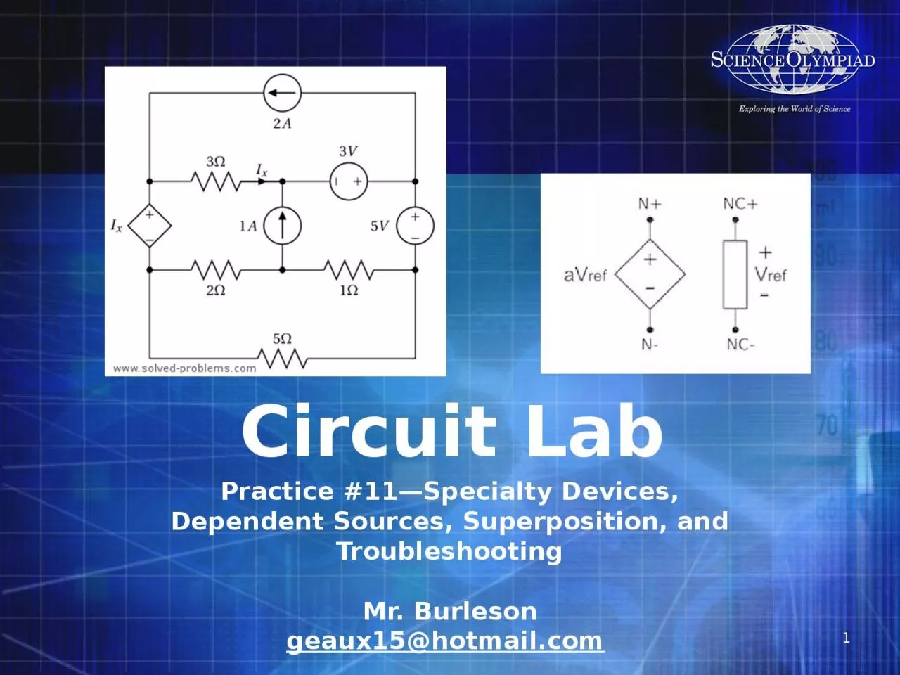
1. Circuit LabPractice #11—Specialty Devices, Dependent Sources, Superposition, and TroubleshootingMr. Burlesongeaux15@hotmail.com
2. Multiple SourcesSometimes a circuit has more than one sourceVoltage Sources should be added in seriesCurrent Sources should be added in parallelYou shouldn’t put voltage sources in parallel or current sources in series, as it can create a situation that violates circuit rules.2
3. Kirchhoff's Voltage Law (KVL)(Division C Only)The directed sum of the electrical potential differences (voltage) around any closed network is zeroor: the sum of the voltage in any closed loop is equivalent to the sum of the potential drops in that loop3
4. Kirchhoff's Current Law (KCL)(Division C Only)At any node (junction) in an electrical circuit, the sum of currents flowing into that node is equal to the sum of currents flowing out of that nodeor: The algebraic sum of currents in a network of conductors meeting at a point is zero.or: All current into a node equals all current out!4
5. SwitchesA switch is an electrical component that can break an electrical circuit or divert it from one conductor to another.Usually has two states “Open” or “Closed”Open is the circuit is Open or OFFClosed is the circuit is connected/short or ONCan be a Toggle or MomentaryWhen doing switch problems, redraw the circuit for every configuration you want to test.5
6. Types of switchesSingle Pole Single Throw (SPST)—a simple on/off switch. Light switch.Single Pole, Double Throw (SPDT)—a simple change over switch. Turns on one thing or another, not both.Double pole, Single Throw (DPST)—equal to two SPST switches controlled by a single mechanism. Like flipping two light switches at once.Double Pole, Double Throw (DPDT)—equivalent to two SPDT switches controlled by a single mechanism.6
7. FusesA safety device which “burns out” at a given currentPrevents a short or high current from damaging other systems, melting wires, etc. from a short or other problemFuses must be replaced after burn out, but not before the problem is resolved.Usually faster than circuit breakers.7
8. Circuit BreakerA safety device which “trips” at a given currentPrevents a short or high current from damaging other systems, melting wires, etc. from a short or other problemCircuit Breakers may be reset after tripping, but should not be reset unless the problem has been resolved.Usually a little slower than fuses.8
9. Dependent SourcesShown by diamond shapeSources that are dependent upon another element or measurement in a circuit.Could reference other devices like an amplifierUse KVL and KCL to develop an equation and then solve4Vi4Vi+-Dependent Voltage SourceDependent Current Source9
10. Dependent Source Examples10
11. Solving Dependent SourceWith dependent current sourceKVL around left loop10V = i1 10kΩ + i2 2kΩ KCL at node Ai1 = i2 + 2 i1 Subtract 2 i1 from both sides- i1 = i2 Combine equations10 V = i1 10kΩ + (- i1)2kΩ 10 V = i1 (10kΩ - 2kΩ) = i1(8kΩ) i1 = 10 V/8kΩ = 1.25mAi2 = -i1 = -1.25mA2 i1 = 2.5mAAi2i12i111
12. Solving Dependent SourceWith dependent voltage sourceR1 = R2 = R3 = R4 = R5 = 100ΩV1 = 20 V, V2 = 30VSolve for IKVL around loopV1 + V2 + 3VX = IR1 + IR2 + IR3 + IR4 + IR5 VX = IR2 Combine equationsV1 + V2 + 3 IR2 = IR1 + IR2 + IR3 + IR4 + IR5V1 + V2 = IR1 + IR2 - 3 IR2 + IR3 + IR4 + IR5 = I (R1 - 2R2 + R3 + R4 + R5) = I (200Ω)I = (V1 + V2)/200Ω = 50V/ 200Ω = 0.25 A+-+-Vx3Vx12
13. SuperpositionThe superposition theorem for electrical circuits states that for a linear system the response (Voltage or Current) in any branch of a circuit having more than one independent source equals the algebraic sum of the responses caused by each independent source acting alone, while all other independent sources are replaced by their internal impedances.To ascertain the contribution of each individual source, all of the other sources first must be "turned off" (set to zero) by:Replacing all other independent voltage sources with a short circuit (thereby eliminating difference of potential. i.e. V=0, internal impedance of ideal voltage source is ZERO (short circuit)).Replacing all other independent current sources with an open circuit (thereby eliminating current. i.e. I=0, internal impedance of ideal current source is infinite (open circuit).Does NOT work with DEPENDENT SOURCES or POWERWill cover this in more detail later.13
14. TroubleshootingFigure out if it worked previouslyIf it never worked it might be a design errorIf it worked before, something had to changeIf it never worked, check the design for any flaws including Open and Short CircuitsIf it worked before, check for changes:Is power connected? Is it “plugged in”--#1 PROBLEM OF ALL TIMEAre the batteries “dead”? use the voltmeterAre the switches set up right/is it turned onFuse burnt out/circuit breaker trippedLight bulb/resistor/motor burned outWire loose, light bulb looseFigure out the design and draw it outTest the design14
15. Troubleshooting (cont.)If it used to work and it passed the tests on the previous slide, you need to look at the designFirst DRAW and label it!What should the voltage and/or resistance be between nodes? Write it down on your drawingMeasure voltage in parallel to the elements, with the power source on, just like it is running. Compare to your calculations.Measure resistance in parallel to the elements, with the power source removed or switched offBe careful that if you measure resistance you account for both paths between leads. Both between the element you have or any other path back.15
16. Troubleshooting TipsAlways check obvious stuff first (plugged in, battery not dead, switch on, wires connected, nothing loose).Series—they all go outParallel—only the burned out one goes outRemember you only get voltage if you have both Current (I) and Resistance (R) A Short Circuit will have both Voltage and Resistance = zeroAn Open Circuit will have Resistance = Overload “1”, only if there is not another path (i.e. back through the rest of the circuit)The Voltage across a bunch of resistors in series, with no current, will remain the same.The best way to measure resistance is to remove the element being tested and to test it alone. 16
17. Troubleshooting a Series CircuitIn the circuit, all the lights (12 Ω each) were working but stopped suddenly.What are the obvious things to check?What should we measure and how?What should be the resistance and voltage for each element?If everything else checks out and the voltage at L5 = 10V, what’s wrong?6 V+-L1L3L2L5L4L617
18. Troubleshooting a Parallel CircuitIn the circuit, all the lights (12 Ω each) were working but stopped suddenly.What are the obvious things to check?You fix the obvious problem, but still L5 is outWhat should we measure and how?What should the resistance and voltage be for each element?6 V+-L1L3L2L5L4L618
19. Arguing an Illegal QuestionAlways make sure you read the question again to ensure it really is illegal. Event supervisor might have old rules, but double check your rules first.Ask for how to implement the question within the rules. Remove the illegal items like capacitors/inductors/LEDs/etc.Operate it as DC instead of AC.Reference the specific rule, normally in section 3.dSemiconductors include diodes, LEDs, transistors, OpAmps, and integrated circuits. LEDs, Diodes and OpAmps are now allowed in certain circumstances.AC circuit theory includes frequency analysis, two or three phase power, capacitor/inductor reactance. But they can sometimes be made legal by switching to a DC system.AC devices include transformers, rectifiers, others. Most will not work with DC.Several items are only available for Division C and not for B19
20. HomeworkUpdate your binder to get it competition readyComplete the circuit problems from the Homework GeneratorLevel 11 WheatstoneLevel 12 Dependent SourceLevel 13 SuperpositionLevel 14 Norton-TheveninCorrect the problems you missed on the practice competition on separate paper.20