
Stiffness matrix of a beam element Strain energy cont Assembly Symmetric positive semidefinite Proportional to EI Inverse dependence on L What is the basis of the powers of L For the different elements of the matrix ID: 233664
Download Presentation The PPT/PDF document "BEAM STIFFNESS MATRIX" is the property of its rightful owner. Permission is granted to download and print the materials on this web site for personal, non-commercial use only, and to display it on your personal computer provided you do not modify the materials and that you retain all copyright notices contained in the materials. By downloading content from our website, you accept the terms of this agreement.


Slide1
BEAM STIFFNESS MATRIX
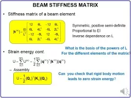
Stiffness matrix of a beam element
Strain energy
cont.Assembly
Symmetric, positive semi-definite
Proportional to EI
Inverse dependence on L
What is the basis of the powers of L
For the different elements of the matrix
?
Can you check that rigid body motion
leads to zero strain energy
?Slide2
EXAMPLE – ASSEMBLYTwo elementsGlobal DOFs
F
3
F
2
y
x
1
2
3
2EI
EI
2L
LSlide3
POTENTIAL ENERGY OF APPLIED LOADS
Concentrated forces and couplesDistributed load (Work-equivalent nodal forces)Slide4
EXAMPLE – WORK-EQUIVALENT NODAL FORCES
Uniformly distributed load
pL/2
pL/2
pL
2
/12
pL
2
/12
p
EquivalentSlide5
FE EQUATION FOR ONE BEAM ELEMENT Finite element equation
for beamOne beam element has four variablesWhen there is no distributed load, p = 0Applying
boundary conditions is identical to truss element
At each DOF, either displacement (v or q) or force (F or C) must be known, not bothUse
standard procedure for assembly, BC, and solutionSlide6
PRINCIPLE OF MINIMUM POTENTIAL ENERGY
Potential energy (quadratic form)PMPEPotential energy has its minimum whenApplying BCThe same procedure with truss elements (striking-the-rows and striking-he-columns)
Solve for unknown nodal DOFs {Q}
[
K
s
] is symmetric & PSD
[
K
] is symmetric & PDSlide7
BENDING MOMENT & SHEAR FORCEBending momentLinearly varying along the beam spanShear forceConstantWhen true moment is not linear and true shear is not constant, many elements should be used to approximate it
Bending stressShear stress for rectangular sectionSlide8
EXAMPLE – CLAMPED-CLAMPED BEAMDetermine deflection & slope at x = 0.5, 1.0, 1.5 m Element stiffness matrices
F
2
= 240 N
y
x
1
2
1 m
3
1 m
Will the solution be exact?Slide9
EXAMPLE – CLAMPED-CLAMPED BEAM cont.Applying BCAt x = 0.5 s = 0.5 and use element 1At x = 1.0 either s = 1 (element 1) or s = 0 (element 2)Slide10
EXAMPLE – CANTILEVERED BEAMOne beam elementNo assembly requiredElement stiffnessWork-equivalent nodal forces
C
= –50 N-m
p
0
= 120 N/m
EI
= 1000 N-m
2
L
= 1mSlide11
EXAMPLE – CANTILEVERED BEAM cont.Support reaction (From assembled matrix equation)Bending momentShear forceSlide12
EXAMPLE – CANTILEVERED BEAM cont.Comparisons
Deflection
Slope
Bending moment
Shear force