
CURRENT SCIENCE VOL 10 6 NO 6 25 MARCH 201 4 841 For correspondence e mail ksahuiithacin Numerical simulations of miscible channel flow with chemical reactions J N Kusuma 1 Om ID: 379610
Download Pdf The PPT/PDF document "RESEARCH ARTICLES" is the property of its rightful owner. Permission is granted to download and print the materials on this web site for personal, non-commercial use only, and to display it on your personal computer provided you do not modify the materials and that you retain all copyright notices contained in the materials. By downloading content from our website, you accept the terms of this agreement.


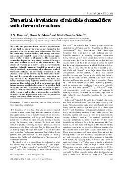
RESEARCH ARTICLES CURRENT SCIENCE, VOL. 10 6 , NO. 6 , 25 MARCH 201 4 841 *For correspondence. (e - mail: ksahu@iith.ac.in) Numerical simulations of miscible channel flow with chemical reactions J. N. Kusuma 1 , Omar K. Matar 2 and Kirti Chandra Sahu 1, * 1 Department of Chemical Engineering, I n dian Institute of Technology Hyderabad, Yeddumailaram 502 205, India 2 Department of Che mical Engineering, Imperial College London, South Kensin g ton Campus, London, SW7 2AZ, UK We study the pressure - driven mi s cible displacement of one fluid by another in a horizontal channel in the presence of an exothermic chem i cal reaction. We solve the c ontinuity, Navier Stokes, and energy conserv a- tion equations coupled to convective discussion equ a- tions of the reactant and product. The viscosity is assumed to depend on the volume fraction of the rea c- tant and product as well as the temperature. The effec ts of relevant parameters such as the Reynolds number, Schmidt number, Damköhler nu m ber and viscosity ratio of the reactant and product are studied . Our results indicate that increasing the inte n sity of the chemical reaction by increasing the Damköhler nu m- ber and decreasing the dimensionless activation e n- ergy increases the displacement rate. We have also found that increasing Re y nolds number leads to more pronounced inst a bilities and roll - up phenomena, which in turn promote rapid displacement of the res i den t fluid inside the channel. Variation of the relative signif i- cance of the heat of rea c tion and the Schmidt numbers of the reactants and products, however, has a neglig i ble influence on the displacement rates for the parameter ranges considered in the pr e se nt work. Keywords: Chemical reaction, laminar flow, miscible flow, numerical simulation. T HE dynamics of two - fluid flows is an a c tive research area due to their central importance to a number of indu s- trial applications, which include enhanced oil recover y, fixed - bed regeneration, hydrology and filtration, tran s- po r tation of crude oil in pipelines 1 , and mixing of liquids using, for instance, static mixers 2 . In food and drink industrial plants, cleaning - in - place processes involve the removal of a highly v iscous fluid by high - speed flow of water pumped through the plant 3 . Thus in the latter case, achieving fundamental understanding of these flows pe r mits the determination of the degree of mixing between the fluids and minimization of the amount of wastewat er utilized. The stability of two - phase flows in a channel or pipe has been widely studied both theoretically 4 6 and exper i- mentally 1,7 9 in the context of immiscible 9 16 and misc i- ble 17 21 fluids. By co n ducting a linear stability analysis, Ern et al. 19 hav e shown that for ra p idly varying viscous stratification, diffusion can be destabilizing. However, Govind a rajan 18 has demonstrated that three - layer Poiseuille flow is unstable at high Schmidt and low Reynolds numbers. In neutrally buoyant, corea n nular flow s, Selvam et al. 6 have shown that, above a critical viscosity ratio, the flow is unstable even when the less viscous fluid is at the wall (a l though it should be noted that the range of parameters over which this is true is li m- ited). This is in contrast to the studies of Joseph et al. 1 , and Malik and Hooper 22 , who found stable flow in this configuration. Several authors 23 27 have also studied miscible core - annular flows experimentally and invest i- gated the thickness of the remnant fluid layer left on the pi pe walls and the speed of the propagating finger tip. The development of different instability patterns, such as axisy m metric corkscrew patterns in miscible flows, has also been studie d 2,28 31 . dOlce et al. 32 o b ser - ved axisy m metric pearl and mushro om patterns in ne u trally buoyant, core - annular horizontal pipe flow at high Schmidt and Reynolds nu m bers in the range 2 Re 60. Sahu et al. 20 studied the st a bility of neutrally buoyant, two - fluid miscible channel flows for large viscosity co n- trasts. They also ca r ried out a generalized spatio - temporal linear stability analysis for the case of a three - layer flow 33 35 and determined the boundaries between conve c- tively and absolutely unstable flows in the space of the Reynolds number and viscosity ratio, for param e terically varying Schmidt number. The vertical gradients of vi s cosity perturbations were found to be the main destabilizing influence. In order to understand the flow dynamics in the nonlinear r e gime, the Navier Stokes equations coupled to a c onvective - diffusion equation for the conce n tration of the more viscous fluid were solved. These transient numer i cal simulations demonstrated the development of co m plex dynamics characterized by roll - up and convective mixing, which increase in intensity w ith increasing viscosity ratio, Reynolds and Schmidt numbers. Selvam et al. 36 also made a similar anal y sis in miscible core - annular flows at high Schmidt number. This system was also studied experimentally by dOlce et al. 37 . They observed absolute instab ilities for a range of core radii for high vi s cosity ratios when the less viscous fluid is in the core. The work of Sahu et al. 20 has been RESEARCH ARTICLES CURRENT SCIENCE, VOL. 10 6 , NO. 6 , 25 MARCH 201 4 842 extended to account for buoyancy effects in inclined cha n nels 38 , and non - isothermal effects in pressure - driven mi s ci ble displacement flow 5 in the nonlinear regime. The results of Sahu et al. 5,38 demonstrated that the rates of mixing and displacement of the more viscous fluid are promoted by the development of Rayleigh Taylor inst a- bilities, and enhanced with i n creasing d ensity ratio, Froude number and viscous heating. The mixing rates were also shown to increase with i n creasing inclination angles when the displaced fluid is also the denser one. In the absence of density co n trast, when a highly viscous fluid displaces a le ss viscous one, the flow becomes u n stable and the famous Saffman Taylor instability 39 occurs at the inte r face separating the fluids. In spite of the large volume of r e search on two - fluid flows, very few studies have considered the effects of chemical reactions on the flow d y namics in pressure - driven displacement flows, although their effects on vi s- cous fingering in porous media have be en examined extensively by several a u thors 40 42 . Nagatsu et al. 43,44 have studied experimentally the reactive viscous finge r- ing in a Hele - Shaw cell and found that the fingering becomes more pronounced when the product is more vi s- cous than the reactant; t he reverse trend was observed for reactions generating a less viscous product. For rel a tively slow reactions, these authors have also shown that finge r- ing becomes more vigorous in the reactive than in the non - reactive case. More recently, Burghelea and Fr i- gaard 45 demonstrated the a p pearance of instability in low - Reynolds number, parallel, miscible channel flows in the presence of rapid chemical reactions. The instability characteristics depend on a number of system p a rameters, which include the channel aspe ct ratio, flow speed and viscosity contrast. In the present work, we examine the flow dynamics of miscible, pressure - driven displacements in horizontal, rectang u lar channels in the presence of exothermic chemical reactions, of the type A + B ï® C , via direct n u- merical simulations. We solve the mass a nd energy co n- servation equations coupled to convective - diffusion equations of the reactant and product, and the full N a vier Stokes equations (rather than Darcys equations, appr o priate for Hele - Shaw flow). The viscosity is assumed to vary with temperatur e and the volume fra c- tion of the reactant and product; the density is assumed to remain constant. The governing equations are paramete r- ized by the Re y nolds, Schmidt and Damköhler numbers, and the viscosity ratio of the reactant and product. Our numerical r esults demonstrate that increasing the inte n- sity of the chemical reaction by i n creasing the Damköhler number and/or decreasing dimensionless activation energy increases the displacement of the resident fluid present inside the channel. We have also found that increasing the Reynolds number leads to more pr o noun - ced instabilities and roll - up phenomena, which increase the displacement rates of the res i dent fluid. Formulation We consider two - dimensional miscible flow in a horizo n- tal channel, wherein, initial ly, the channel is occ u pied by a stationary, viscous fluid of viscosity ï 1 . Another liquid with viscosity ï 2 is injected into the channel with an average velocity V ïº Q f / H , where Q f d e notes the total flow rate; we a s sume the densities of all fluids to be the same. The initially resident and invading fluids are labelled A and B, as shown in Figure 1, and their in i- tial temperatures are denoted by T 1 and T 2 respe c tively. An exothermic second - order chemical reaction of the type A + B ï® C , accompanies the flow which takes place in the mixed region separating the two fluids; this then alters the vi s cosity in this region. The quantities, ï¦ m and ï¦ p are defined as the volume f ra c tions of reactant A and product C ; the latter is initially equal to zero. The vo l ume fraction of r e actant B is then simply equal to 1 ï¦ m ï¦ p . A rectangular coord i nate system ( x , y ) is used to model the flow dynamics, where x and y denote the coo r dina tes in the axial and vertical directions respectively. The channel inlet and outlet are located at x = 0 and x = L respectively. The channel walls, which are rigid and impermeable are l o cated at y = ï± H /2. The equations governing the pro b lem can be written as: ï ï u = 0, (1) [()], T p t ï²ï ï¶ ï©ï¹ ï«ïïïïïï«ïïïï«ï ïªïº ï¶ ï«ï» u uuuu (2) 2 (1), m mmmmmp k t ï¦ ï¦ï¦ï¦ï¦ï¦ ï¶ ï«ïïïïïïï ï¶ u ï (3) 2 2(1), p pppmmp k t ï¦ ï¦ï¦ï¦ï¦ï¦ ï¶ ï«ïïïïï«ïï ï¶ u ï (4) 2 (1), mmp T TTkq t ï¡ï¦ï¦ï¦ ï¶ ï«ïïïïï«ïï ï¶ u (5) where u , p and T denote the velocity, pressure a nd te m perature fields of the fluids respectively; ï m and D p are the diffusion coefficients of the reactant and product Figure 1. Schematic diagram showing the initial flow configuration. Fluid A o c cupies the entire channel, and is about to be displac ed by the in flow ing fluid B. Sy m bols are defined in the text. RESEARCH ARTICLES CURRENT SCIENCE, VOL. 10 6 , NO. 6 , 25 MARCH 201 4 843 respectively; ï¡ denotes the thermal diffusivity and q is the heat of the reaction. In eqs (3) (5) , the rate of rea c- tion is d e fined as k ( T ) = k 0 exp( E / RT ), (6) where k 0 is the pre - exponential factor, E the activation energy and R is the universal gas constant. The viscosity of the fluid is assumed to depend on temperature and the volume fractions of the reactant and pro d uct as follows: 11 (()/) 21 ()e, mmpp RRTTT T ï¦ï¦ ïï ï©ï¹ ï«ïï ï«ï» ï (7) where R m ( ïº ln( ï 1 ( T 1 )/ ï 2 ( T 1 ))) and R p ( ïº ln( ï p ( T 1 )/ ï 2 ( T 2 ))) are the log - mobility ratios of the reactant and product r e spectively. The following scaling is e m ployed in order to render the governing equations dimensionless: (,)(,),,(,)(,), H xyHxyttuvVuv V ïïï ï¥ ï¥ï¥ï¥ï¥ 2 , pVp ï² ï ï¥ 2111 (),, TTTTT ïïï ïïï« ï¥ ï¥ (8) where the tildes designate dime n sionless quantities. After dropping tildes from all non - dimensional terms, the go v- erning dimensionless equ a tions are given by: ï ï u = 0, (9) 1 [()], T p tRe ï ï¶ ï«ïïïïïï«ïïïï«ï ï¶ u uuuu (10) 2 1 m mm m tReSc ï¦ ï¦ï¦ ï¶ ï«ïïïï ï¶ u /(1) e(1), T mmp Da ï¢ ï¦ï¦ï¦ ïï« ïïï (11) 2 1 p pp p tReSc ï¦ ï¦ï¦ ï¶ ï«ïïïï ï¶ u /(1) 2e(1), T mmp Da ï¢ ï¦ï¦ï¦ ïï« ï«ïï (12) 2 1 T TT tRePr ï¶ ï«ïïïï ï¶ u /(1) e(1), T mmp Da ï¢ ï¦ï¦ï¦ ïï« ï«ïï ï (13) where Re ïº ï² VH / ï 2 ( T 1 ) denotes the Reynolds number, Sc i ïº ï 2 ( T 1 )/ ï² ï i ( i = m , p ) represent the Schmidt nu m bers of the reactant and product; ï ïº q / T 1 ï² c p is the dime n- sionless heat of reaction, and Da ïº k 0 H / V and Pr ïº c p ï 2 ( T 1 )/ ï¡ are the Damköhler number and Prandtl nu m- ber respectively, wherein c p is the specific heat c a pacit y at constant pressure. The dimensionless a c tivation energy is given by ï¢ = E / RT 1 , while the dimensionless temper a- ture of the invading fluid is e x pressed by r T = ( T 2 T 1 )/ T 1 . Finally, the dimensionless viscosity ï has the following depen d ence on T , ï¦ m and ï¦ p : ï = exp( R m ï¦ m + R p ï¦ p T ). (14) Numerical methods We use a finite - volume approach similar to the one d e veloped by Ding et al. 46 in order to solve the system of equations (9) (14). These equations are discretized using a staggered grid; the scalar va riables (pressure, temper a- ture and volume fraction) are defined at the centre of each cell and the velocity components are defined at the cell faces. The discretized advection diffusion equations for the r e actant and product, and the energy equation are gi ven by: 11 21 1.520.5 1 nnn n mmm m m tReSc ï¦ï¦ï¦ ï¦ ï«ï ï« ïï« ïï ï 11 2()() nnnn mm ï¦ï¦ ïï ïïïï«ïï uu /(1) e(1), T mmp Da ï¢ ï¦ï¦ï¦ ïï« ïïï (15) 11 21 1.520.5 1 nnn ppp n p p tReSc ï¦ï¦ï¦ ï¦ ï«ï ï« ïï« ïï ï 11 2()() nnnn pp ï¦ï¦ ïï ïïïï«ïï uu /(1) e(1), T mmp Da ï¢ ï¦ï¦ï¦ ïï« ï«ïï (16) 11 21 1.520.5 1 nnn n TTT T tRePr ï«ï ï« ïï« ïï ï 11 2()() nnnn TT ïï ïïïï«ïï uu /(1) e(1), T mmp Da ï¢ ï¦ï¦ï¦ ïï« ï«ïï ï (17) where ï t = t n + 1 t n and the superscript n signifies the discretized n th step. In order to discretize the a d vective terms in eqs (15) (17), a weighted essentially non - oscillatory (WENO) scheme is used, while a centred - d ifference scheme is used to discretize the diffusive terms on the right - hand sides of these equations. RESEARCH ARTICLES CURRENT SCIENCE, VOL. 10 6 , NO. 6 , 25 MARCH 201 4 844 In order to achieve second - order accuracy in the temporal discr e tization, the Adams Bashforth and Crank Nicolson methods are used for the advective and second - order dissipation terms respectively in eq. (10). This r e- sults in the follo w ing discretized equation: 1 * [1.5()0.5()] n nn t ï ï¬ ï ï¯ ïïï ï ï ï¯ ï® uu uu ïï 1 1 [(*,)(,)], 2 nnn Re ïï ï« ï¼ ï«ï« ï½ ï¾ uu ïï (18) where u * is the intermediate velocity, and ï and ï d e note the discrete conv ection and diffusion operators respectively. The intermediate velocity u * is then co r- rected to ( n + 1) th time level as follows 1 1/2 * . n n p t ï« ï« ï ïï ï uu (19) The pressure distribution is o b tained from the continuity equ a tion at time step n + 1 using 1/2 * (). n p t ï« ïï ïïïï ï u (20) At the top and bottom walls, solutions of the above di s cretized equations are subject to no - slip, no - penetration conditions for the velocity, and no - flux co n dition for the temperature and the volume fractions of the rea c tant and product. A fully - developed velocity profile with a co n- stant flow rate taken to be unity is imposed at the inlet ( x = 0), and Neumann boundary conditions are used at the outlet ( x = L). The following steps are employed in our numerical solver in order to solve eqs (9) (13): ï· The temperature field and volume fractions of the r e actant and product are updated by solving eqs (11) (13) with the velocity field at time steps n and n 1. ï· The velocity field is then u p dated to time - step n + 1 by sol v i ng eqs (9) and (10). The numerical procedure d e scribed above was originally developed by Ding et al. 46 in the context of i n terfacial flows. Sahu et al. 20,38 then modified this procedure to simulate pressure - driven, ne u trally buoyant miscible channel flow with high viscosity contrast. The readers may refer to our earlier papers 20,38 for the validation and st a bility of the numerical scheme used in the present study. The results are presented next. Results and discussion We begin the presentation of our r e sul ts by conducting a mesh refinement test to show the convergence of the numerical method. The temporal evolution of a dime n- sionless measure of the mass of the di s placed fluid A, M 0.95 / M 0 , is plotted in Figure 2 a for Re = 500, Pr = 7, Sc m = 100, Sc p = 50, Da = 0.1, r T = 1, ï¢ = 1, ï = 50, R m = 2 . 3026 and R p = 1.609. Here, M 0.95 and M 0 d e note the mass of fluid with ï¦ m ï³ 0.95, and that of fluid A in i- tially occupying the channel respectively. The p a rameter values ch o sen are characteristic of a situation where a cold fluid is displaced by a hot fluid of lower viscosity and the viscosity of the product due to the chemical rea c- tion is lower than that of the r e actant. Inspection of Figure 2 a reveals that M 0.95 / M 0 unde r- goes an almost linear decrease at the earlier stages of flow due to its di s placement by fluid B. The slope of the curve during this linear stage (before the front separa t- ing the fluids has reached the channel exits) is consider a- bly steeper than that of the line represented by 1 tH / L , which corresponds to the plug flow displacement of fluid A by fluid B. At approximately t = 30 for this set of p a rameters, when the front of the displacing fluid B reach es the end of simulation domain, transition to another linear regime occurs; the slope of the M 0.95 / M 0 versus time plot in this regime is much smaller than the previous one. At this later stage, the flow dynamics is controlled by diffusion. The temporal variation of the spatial location of the lea d ing front, or finger, separating the two fluids, x tip is plotted in Figure 2 b ; this exhibits a linear dependence on time, the slope of which provides an est i mate of the front speed 5,20,38 . The res ults in Figure 2 b are obtained u s ing different grid points for the same computational d o main. It is ev i dent that convergence of the results has been achieved upon mesh refinement as the curves are virt u- ally indistinguishable for different mesh sizes. The front velocity of the finger, obtained using di f ferent sets of grid points, is also compared in Table 1. In view of this observed small effect of the grid, the rest of the comput a- tions presented in this article were performed u s ing 41 ï´ 701 grid points, i n a channel of aspect ratio of 1 : 40. The spatio - temporal evolution of ï¦ m , ï¦ p , T and ï fields for the same parameter values as those used to ge n erate Figure 2 is shown in Figure 3 a d , respe c tively. Figure 3 a shows that the di s placement of fluid A by a finger of the less viscous and warmer fluid B leaves behind virt u- ally no trace of the former adhe r ing to the channel walls. It is also seen that mild Kelvin Helmholtz - type roll - up phenomena become apparent at the diffuse interface sep a rating the two fl uids at later times; these phenomena become pronounced at higher viscosity r a tios Re and Sc . The effects are the same as those found in the non - reacting flow in the channel 20,32 . The volume fra c tion of the product of the chemical reaction that takes place b e- tween fluids 1 and 2, depicted in Figure 3 b , is highest in the diffuse interf a cial region at early times; at later times, the convective mixing brought about by the roll - up ph e no - mena entrain the product from the wall r e gion into the RESEARCH ARTICLES CURRENT SCIENCE, VOL. 10 6 , NO. 6 , 25 MARCH 201 4 845 Figure 2. a , Mass fraction M 0.95 = M 0 of ï¦ m and b , temporal evolution of the position of the leading front separating the two fluid s, x tip for diffe r ent grid densities. The rest of the parameter values are Re = 500, Pr = 7, Sc m = 100, Sc p = 50, Da = 0.1, r T = 1, ï¢ = 1, ï = 50, R m = 2.3026 and R p = 1.609. Dotted lines in panel ( a ) and ( b ) represent the limiting case given by M 0.95 / M 0 = 1 tH / L and x tip = t respe c tively. Figure 3. Spatio - temporal evolution of the contours of ( a ) ï¦ m , ( b ) ï¦ p , ( c ) T and ( d ) ï at successive times (from top to bottom: t = 10, 20 and 25). The rest of the parameter values are the same as those used to generate Figure 2. The colour maps are shown at the bottom. Table 1. Velocity of the fingertip, V f , for different grid densities. The rest of the p a rameter values are the same as those used to generate Fi g ure 2. Grid V f 41 ï´ 701 1.584 61 ï´ 701 1.587 41 ï´ 1001 1.56 core. The mixing action of the rol l - up inst a bilities is also clearly seen in the case of the te m perature within the channel shown in Figure 3 c . In contrast, very little mi x- ing can be seen in the case of the viscosity ï , which exhibits similar patterns to those associated with the d y nami cs of fluids 1 and 2, as shown in Figure 3 d ; this is due to the d e pendence of ï on ï¦ m through the term exp( R m ï¦ m ) in eq. (14) which for the parameter values used to generate Figure 3, is the dominant contrib u tion to that equation. To compare this dynamics to a re f erence case, the sp a tio - temporal evolution of ï¦ m , ï¦ p , T and ï fields for r T = 0, with the rest of the parameter values remaining the same as in Figure 2, is shown in Figure 4 a d , respectively. In this case, there is no imposed te m- perature gradie nt, i.e. the system is isothermal at t = 0. Ho w ever, at later times, a temperature gradient arises due to heat generation by the exothermic chemical rea c tion. It can be clearly seen in Figure 4 c that the temperature is maximum at the interfacial region wh ere the r e action takes place. Next, we examine the parametric dependence of the temporal variation of M 0.95 / M 0 on Da , which provides a RESEARCH ARTICLES CURRENT SCIENCE, VOL. 10 6 , NO. 6 , 25 MARCH 201 4 846 Figure 4. Spatio - temporal evolution of the contours of ( a ) ï¦ m , ( b ) ï¦ p , ( c ) T and ( d ) ï at successive times (from top to bottom: t = 10, 20 and 25) for r T = 0 (at t = 0 flow is isothermal). The rest of the parameter values are the same as those used to generate Figure 2. The colour maps are shown at the bo t tom. Figure 5. ( a , c ), Mass fraction M 0.95 / M 0 of ï¦ m , and ( b , d ), temporal evolution of the position of the leading front separa t- ing the two fluid s, x tip for di f ferent values of Da . ( a , b ) and ( c , d ), correspond to the parameters ( R m = 2.3026 and R p = 1.609) and ( R m = 1.609 and R p = 2.3026) respectively. Th e rest of the parameter va l ues are Re = 500, Pr = 7, Sc m = 100, Sc p = 50, r T = 1, ï¢ = 1 and ï = 50. Dotted lines in ( a , c ) and ( b , d ) represent the limi t ing case given by M 0.95 / M 0 = 1 tH / L and x tip = t respectively. d i mensionless measure of the relati ve importance of chemical reactions in this flow. This is shown in Figure 5 with the rest of the parameters r e maining unaltered from those used to generate Figures 2 and 3. Figure 5 a shows that increasing the relative inte n sity of chemical reaction by inc reasing Da leads to more rapid displacement in comparison to displacement without chemical rea c tions ( Da = 0). It can be seen that all the curves in Figure 5 a RESEARCH ARTICLES CURRENT SCIENCE, VOL. 10 6 , NO. 6 , 25 MARCH 201 4 847 lie below the 1 tH / L curve that co r responds to a plug - flow - type displacement in which the int erface separa t- ing the fluids remains vertical throug h out; the curves closest to the 1 tH / L line are those ass o ciated with Da = 0. In Figure 5 b , it is clearly seen that increasing Da leads to an i n crease in the speed of the penetrating front. Figu re 6. Spatio - temporal evolution of the contours of ï¦ m for ( a ) Da = 0 and ( b ) Da = 0.5 at successive times (from top to bottom in each panel: t = 5, 10, 15 and 20) for R m = 2. 3026 and R p = 1.609. The rest of the parameter values are the same as those used to generate Fi g ure 5. Colour map is shown at the bottom. Figure 7. Spatio - temporal evolution of the contours of ï for ( a ) Da = 0 and ( b ) Da = 0.5 at successive times (from top to bottom in each panel: t = 5, 10, 15 and 20) for R m = 2.3026 and R p = 1.6 09. The rest of the parameter values are the same as those used to generate Fi g ure 5. Colour map is shown at the bottom. The spatio - temporal evolution of the ï¦ m fields assoc i- ated with Da = 0 and 0.5 is shown in Figure 6 a and b r e spectively. It can be s een in Figure 6 a that for Da = 0, the remnants of ï¦ m assume the form of thin layers Figure 8. Spatio - temporal evolution of the contours of ï¦ m for ( a ) Da = 0 and ( b ) Da = 0.5 at successive times (from top to bottom in each panel: t = 5, 10, 15 and 2 0) for R m = 1.609 and R p = 2.3026. The rest of the parameter values are the same as those used to generate Fi g ure 5. Colour map is shown at the bottom. Figure 9. Spatio - temporal evolution of the contours of ï for ( a ) Da = 0 and ( b ) Da = 0.5 at succ essive times (from top to bottom in each panel: t = 5, 10, 15 and 20) for R m = 1.609 and R p = 2.3026. The rest of the parameter values are the same as those used to generate Fi g ure 5. Colour map is shown at the bottom. RESEARCH ARTICLES CURRENT SCIENCE, VOL. 10 6 , NO. 6 , 25 MARCH 201 4 848 Figure 10. a , Mass fraction M 0 .95 / M 0 of ï m , and b , temporal evolution of the position of the leading front separating the two fluid s, x tip for different values of the dimensionless activation energy ï¢ . The rest of the p a rameter values are Re = 500, Pr = 7, Sc m = 100, Sc p = 50, r T = 1, Da = 0.1, ï = 50, R m = 2.3026 and R p = 1.609. Dotted lines in panel ( a ) and ( b ) represent the limiting case given by M 0.95 / M 0 = 1 tH / L and x tip = t , respe c tively. Figure 11. Spatio - temporal evolution of the contours of ï¦ m for diffe r- ent values of the dimensionless activation e n ergy, ï¢ : ( a ) ï¢ = 0.5 and ( b ) ï¢ = 10 at su c cessive times (from top to bottom in each panel: t = 5, 10, 15 and 20). The rest of the p a rameter values are t he same as those used to generate Figure 10. Colour map is shown at the bottom. adjacent to the upper and lower channel walls. Also ev i- dent are roll - up instabilities that lead to vigorous, conve c- tive mixing of the two fluids. In the reactive flow case ( D a = 0.5), shown in Figure 6 b , the flow dyna m ics is rather less complex: the interfacial region r e mains more parabolic than in the no n reactive case, with a well - defined nose and less evidence of instabi l ity. It can also be seen that reactive displaceme nts appear to be faster and more efficient than non - reactive ones, with very little fluid A left at the walls. This is because the visco s ity of the wall layers is significantly lower in the case of rea c- tive displacements (see Figure 7), which facilitates t heir removal. Thus the displacement rate increases with i n- creasing Da (shown in Figure 5 a ). Interestingly, we have found that even for R p � 0, i.e. when ï 2 ï p ï 1 , the chemical reaction helps in the cleaning process by i n creasing the displacement rate as shown in Figure 5 c , generated for R m = 1.609 and R p = 2.3026, with the rest of the param eter values remai n- ing una l tered from Figure 5 a . Close inspection of the ï¦ m field in Figure 8 b , ho w ever, shows that the parabolic nose shape, characteristic of the interf a cial region in the R p 0 case (shown in Figure 6 b ), has given way to a sharper st ructure whose tip becomes increasingly elo n- gated with time. In case of miscible flow without chem i cal reaction, this type of finger of the inva d ing fluid with sharp nose was observed experimentally by Petitjeans and Maxwo r thy 25 , and numerically by Rakotoma lala et al. 47 . The viscosity fields for Da = 0 and Da = 0.5 with the rest of the parameter values same as Figure 5 c and d are shown in Figure 9 a and b respe c tively. In this case, it can be seen that the viscosity of the fluid in front of the invading fi nger becomes significantly lower co m pared to that of the fluid initially present in this region, which a c celerates the displacement process. The effect of varying the dimensionless activation energy ï¢ , on the displac e ment process is shown in Figure 10. The temp o ral evolution of the dimensionless mass of the di s placed fluid A, M 0.95 / M 0 , and the position of the leading front separating the two fluids, x tip , are plo t ted for different values of ï¢ in Figure 10 a and b , respe c tively; the rest of the parameters remain unaltered from Figure 2. As e x pected, increasing the values of ï¢ , which raises the activation energy barrier for the chemical reaction , decreases the displacement rate (see Figure 10 a ). Fi g ure 10 b reveals that the velocity of the leading front also d e- creases with increasing ï¢ . The spatio - temporal evol u tion of the ï¦ m fields associated with ï¢ = 0.5 and 10 is shown in Figure 11 a and b r espe c tively. As expected, it can be seen that the flow dynamics ass o ciated with higher RESEARCH ARTICLES CURRENT SCIENCE, VOL. 10 6 , NO. 6 , 25 MARCH 201 4 849 Figure 12. a , Mass fraction M 0.95 / M 0 of ï¦ m and b , temporal evolution of the position of the leading front separating the two fluid s, x tip for different values of th e dimensionless temperature of the invading fluid , r T . The rest of the p a rameter values are Re = 500, Pr = 7, Sc m = 100, Sc p = 50, Da = 0.05, ï¢ = 5, ï = 50, R m = 2.3026 and R p = 1.609. Do t ted lines in a and b represent the limiting case given by M 0.95 / M 0 = 1 tH / L and x tip = t , respectively. Figure 13. Spatio - temporal evolution of ï¦ m for different values of the dimensionless temper a- ture of the invading fluid , r T : a , r T = 0 and b , r T = 5 at successive times (from top to bottom in each panel: t = 5, 10, 15 and 20). The rest of the parameter values are the same as those used to generate Figure 12. Colour map is shown at the bo t tom. ï¢ value is qualit a tively similar to that associated with the smaller Da value consi d ered. Next, in Figure 12 we study the effect of r T with Da = 0.05, ï = 200 and ï¢ = 5, the dimensionless te m pe - rature of the invading fluid (fluid B) on the displac e ment characteristics. The rest of the param e ter values remain unaltered from Figure 2. It can be seen in Figure 12 a that increa s ing r T progressively from 0 to 5 leads to more rapid displacement of fluid A in comparison to the is o- thermal case. In Figure 12 b , it can be seen that the pos i- tion of the leading front separating the two fluids, x tip , is weakly dependent on variation in r T values. It can also be seen that all the curves in F igure 12 a lie b e low 1 tH / L (and these in Figure 12 b are above x tip = t ), which corresponds to plug flow displacements. This is due to the presence of instabilities which enhance mixing and i n crease the displacement rate. The above results are rationa lized by examining the spatio - temporal evolution of ï¦ m contours for r T = 0 and r T = 5 in Figure 13 a and b respectively. The rest of the parameter values remain unchanged from those used to generate Figure 12. r T = 5 co r responds to the case when a warmer f luid displaces a cooler one. For r T = 0 (isothe r- mal flow at t = 0), it can be seen that fluid A is pen e trated by a rel a tively stable finger of fluid B at the early times ( t 10). Similar observ a tions were made by Sahu et al. 5 , RESEARCH ARTICLES CURRENT SCIENCE, VOL. 10 6 , NO. 6 , 25 MARCH 201 4 850 Figure 14. a , Mass fraction M 0.95 / M 0 of ï¦ m , and b , temporal evolution of the position of the leading front separating the two fluid s, x tip for different values of Re . c , Spatio - temporal evolution of ï¦ m at t = 20 for different Reynolds nu m bers (from top to bottom in each panel: Re = 50, 100, 500 and 1000). The rest of the parameter values are Pr = 7, Sc m = 100, Sc p = 50, r T = 1, Da = 0.1, ï¢ = 5, ï = 50, R m = 2.3026 and R p = 1.609. Dotted lines in ( a ) and ( b ) represent the limiting case given by M 0.95 / M 0 = 1 tH / L an d x tip = t r e spectively. Figure 15. ( a , c ) Mass fraction M 0.95 / M 0 of ï¦ m , and ( b , d ) temporal evolution of the position of the leading front separa t- ing the two fluid s, x tip . ( a , b ) and ( c , d ) are plotted for different values of Sc m for Sc p = 50, an d Sc p for Sc m = 100 respe c- tively. The rest of the parameter va l ues are Re = 500, Pr = 7, r T = 1, Da = 0.1, ï¢ = 1, ï = 50, R m = 2.3026 and R p = 1.609. Dotted lines in ( a ) and ( b ) represent the limiting case given by M 0.95 / M 0 = 1 tH / L and x tip = t respe ctively. RESEARCH ARTICLES CURRENT SCIENCE, VOL. 10 6 , NO. 6 , 25 MARCH 201 4 851 Figure 16. a , Mass fraction M 0.95 / M 0 of ï¦ m , and b , temporal evolution of the position of the leading front separating the two fluid s, x tip for diffe r ent values of ï . The rest of the parameter values are Re = 500, Pr = 7, Sc m = 100, Sc p = 50, r T = 1, Da = 0.1, ï¢ = 1, R m = 2.3026 and R p = 1.609. Dotted lines in ( a ) and ( b ) represent the limiting case given by M 0.95 / M 0 = 1 tH / L and x tip = t r e spectively. who studied the displacement flow without chemical reaction. In co n trast to the r T = 0 case, for r T = 5, the flow appears to be considerably more unstable due to the ass o- ciated increase in viscosity contrasts. As a result, the r e gion separating fluids 1 and 2 is highly diffuse and hence a higher displacement rate is observed for r T = 5 co mpared to r T = 0. Finally, we have studied the effect of varying Re on the flow dynamics. As shown in Figure 14, increa s ing Re leads to more pronounced roll - up phenomena, highly convective mixing and rapid displacement rates. Vari a- tion of Sc m , Sc p and ï w as also found to have a neglig i ble effect on the displacement rates, as shown in Figures 15 and 16. Conclusion Pressure - driven displacement of one fluid by another in a horizontal channel in the presence of an exothermic chemical reaction is studied numeri cally. In our simul a- tions, the continuity, Navier Stokes and e n ergy equations coupled to two convective - diffusion equations of the r e actant and product, are solved using a finite - volume approach. The vi s cosity is assumed to be an exponential function of the temperature as well as the volume fraction of the reactant and product. In order to isolate the effects of viscosity contrast, the density is assumed to be co n- stant. The effects of relevant parameters such as the Re y nolds number, Schmidt number, Damkö hler number and viscosity ratio of the reactant and product are invest i- gated. The results of the present study ind i cate that increasing the intensity of the chemical reaction by increasing Da m- köhler number and decreasing dimensionless act i vation energy in creases the displacement rate. For situ a tions characterized by a product vi s cosity that is lower than that of the reactants, the viscosity of the fluid layers adj a- cent to the wall is lower in the presence of chemical rea c- tions than in the unreactive case, which facil i tates their removal. For cases wherein the product viscosity is i n- termediate b e tween that of the reactants, it is the fact that the chemical reaction reduces the vi s cosity of the resident fluid ahead of the displacing fluid that promotes its di s- plac e ment. More pronounced instabilities and roll - up phenomena are observed with increasing Reynolds nu m- ber, which increases the displacement rate of the res i dent fluid inside the channel. For the parameter range consi d- ered, we found that the heat of reac tion and the Schmidt numbers of the reactant and product have a negligible i n- fluence on the displacement characteri s tics. The present simulations are two - dimensional and it will be i n teresting to study the effects of chemical reaction in a three - dimensiona l channel. However, i n tuitively we can expect a more profound effect of chemical rea c tion in that case. It will also be interes t ing to conduct experiments in such flow systems. 1. Joseph, D. D., Bai, R., Chen, K. P. and Renardy, Y. Y., Core - annular flows. Annu. Rev. Fluid Mech. , 1997, 29 , 65 90 . 2. Cao, Q., Ventresca, L., Sreenivas, K. R. and Prasad, A. K., Inst a- bility due to viscosity stratification downstream of a centreline inje c tor. Can. J. Chem. Eng ., 2003, 81 , 913 922 . 3. Regner, M., Henningsson, M., Wiklu nd, J., Östergren, K. and Trägårdh, C., Predicting the displacement of yoghurt by water in a pipe using CFD. Chem. Eng. Technol. , 2007, 30 , 844 853 . 4. Fernandez, J., Kurowski, P., Petitjeans, P. and Meiburg, E., De n- sity driven unstable flows of miscible flui ds in a Hele - Shaw cell, J. Fluid Mech. , 2002, 451 , 239 260 . 5. Sahu, K. C., Ding, H. and Matar, O. K., Numerical simulation of nonisothermal pressure - driven miscible channel flow with viscous heating. Chem. Eng. Sci ., 2010, 65 , 3260 3267 . 6. Selvam, B., Merk, S ., Govi n darajan, R. and Meiburg, E., Stability of miscible core - annular flows with viscosity stratification. J. Fluid Mech ., 2007, 592 , 23 49 . 7. Hu, H. H. and Joseph, D. D., Lubricated pipelining: stability of core - ann u lar flows. Part 2. J. Fluid Mech ., 198 9, 205 , 395 396 . 8. Joseph, D. D. and Renardy, Y. Y., Fundamentals of two - fluid d y namics. Part II: Lubricated Transport, Drops and Miscible Li q uids , Springer - Verlag, New York, 1992. RESEARCH ARTICLES CURRENT SCIENCE, VOL. 10 6 , NO. 6 , 25 MARCH 201 4 852 9. Hickox, C. E., Instability due to viscosity and density stratif i cation in a xisymmetric pipe flow. Phys. Fl u ids , 1971, 14 , 251 262 . 10. Yih, C. S., Instability due to viscous stratification. J. Fluid Mech ., 1967, 27 , 337 352 . 11. Joseph, D. D., Renardy, M. and Renardy, Y. Y., Instability of the flow of two immiscible liquids with differen t viscosities in a pipe. J. Fluid Mech ., 1984, 141 , 309 317 . 12. Kouris, C. and Tsamopo u los, J., Dynamics of axisymmetric core - annular flow in a straight tube. I. The more viscous fluid in the core, ba m boo waves. Phys. Fluids , 2001, 13 , 841 858 . 13. Kouris, C. and Tsamopo u los, J., Dynamics of axisymmetric core - annular flow in a straight tube. II. The less viscous fluid in the core, saw tooth waves. Phys. Fluids , 2002, 14 , 1011 1029 . 14. Sahu, K. C. and Matar, O. K., Three - dimensional convective and absolute instabiliti es in pressure - driven two - layer channel flow. Int. J. Multiphase Flow , 2011, 37 , 987 993 . 15. Sahu, K. C. and Matar, O. K., Three - dimensional linear inst a bility in pressure - driven two - layer channel flow of a Newtonian and a Herschel Bulkley fluid. Phys. Fluids , 2010, 22 , 112 - 103. 16. Sahu, K. C., Valluri, P., Spelt, P. D. M. and Matar, O. K., Linear instability of pressure - driven channel flow of a Newtonian and Herschel Bulkley fluid. Phys. Fluids , 2007, 19 , 122101. 17. Ranganathan, B. T. and Govindarajan, R., Stabilis ation and dest a- bilization of channel flow by location of viscosity - stratified fluid layer. Phys. Fluids , 2001, 13 (1), 1 3 . 18. Govindarajan, R., Effect of miscibility on the linear instability of two - fluid channel flow. Int. J. Mult i phase Flow , 2004, 30 , 1177 1192 . 19. Ern, P., Charru, F. and Luchini, P., Stability analysis of a shear flow with strongly stratified visco s ity. J. Fluid Mech. , 2003, 496 , 295 312 . 20. Sahu, K. C., Ding, H., Valluri, P. and Matar, O. K., Linear stabi l- ity analysis and numerical simulation of miscible channel flows. Phys. Fluids , 2009, 21 , 042104. 21. Sahu, K. C. and Govindar a jan, R., Linear stability of double - diffusive two - fluid channel flow. J. Fluid Mech ., 2011, 687 , 529 539 . 22. Malik, S. V. and Hooper, A. P., Linear stability and e n ergy growth of viscosity stratified flows. Phys. Fluids , 2005, 17 , 024101. 23. Taylor, G. I., Deposition of viscous fluid on the wall of a tube. J. Fluid Mech ., 1961, 10 , 161 165 . 24. Cox, B. G., On driving a viscous fluid out of a tube. J. Fluid Mech ., 1962, 14 , 81 96 . 25. Petit jeans, P. and Maxworthy, P., Miscible displacements in capillary tubes. Part 1. Experiments. J. Fluid Mech. , 1996, 326 , 37 56 . 26. Chen, C. - Y. and Meiburg, E., Miscible displacement in capillary tubes. Part 2. Numerical simulations. J. Fluid Mech ., 1996, 326 , 57 90 . 27. Kuang, J., Maxworthy, T. and Petitjeans, P., Miscible displac e- ments between silicone oils in capi l lary tubes. Eur. J. Mech. , 2003, 22 , 271 277 . 28. Lajeunesse, E., Martin, J., Rakotomalala, N. and Salin, D., 3D instability of miscible displacements in a Hele - Shaw cell. Phys. Rev. Lett ., 1997, 79 , 5254 5257 . 29. Lajeunesse, E., Martin, J., Rakotomalala, N., Salin, D. and Yor t- sos, Y. C., Miscible displacement in a Hele - Shaw cell at high rates. J. Fluid Mech ., 1999, 398 , 299 319 . 30. Scoffoni, J., Lajeunesse, E. and Homsy, G. M., Interface instabil i- ties during displacement of two misc i ble fluids in a vertical pipe. Phys. Fluids , 2001, 13 , 553 556 . 31. Gabard, C. and Hulin, J. - P., Miscible displacement of non - Newtonian fluids in a vertical tube. Eur. Phys. J . E , 2003, 11 , 231 241 . 32. dOlce, M., Martin, J., R a kotomalala, N., Salin, D. and Talon, L., Pearl and mushroom instability patterns in two miscible fluids core ann u lar flows. Phys. Fluids , 2008, 20 , 024104. 33. Huerre, P. and Monkewitz, P. A., Local and global instability in spatially developing flows. Annu. Rev. Fluid Mech ., 1990, 22 , 473 537 . 34. Chomaz, J. - M., Global inst a bilities in spatially developing flows: nonnormality and nonlinearity. Annu. Rev. Fluid Mech. , 2005, 37 , 357 392 . 35. Schmid, P. J. and Henningson, D. S., Sta bility and Transition in Shear Flows , Springer, New York, 2001. 36. Selvam, B., Talon, L., Lesshafft, L. and Meiburg, E., Conve c- tive/absolute instability in miscible core - annular flow. Part 2. Numerical sim u lations and nonlinear global modes. J. Fluid Mech ., 2 009, 618 , 323 348 . 37. dOlce, M., Martin, J., R a kotonalala, N., Salin, D. and Talon, L., Convective/absolute instability in miscible core - annular flow. Part 1: Exper i ments. J. Fluid Mech. , 2009, 618 , 305 322 . 38. Sahu, K. C., Ding, H., Va l luri, P. and Matar, O. K ., Pressure - driven miscible two - fluid channel flow with density gradients. Phys. Fluids , 2009, 21 , 043603. 39. Saffman, P. G. and Ta y lor, G. I., The penetration of a fluid into a porous medium or Hele - Shaw cell containing a more viscous li q uid. Proc. R. Soc. London , Ser. A , 1958, 245 , 312 329. 40. De Wit, A. and Homsy, G. M., Nonlinear interactions of chemical r e actions and viscous fingering in porous media. Phys. Fluids , 1999, 11 (5), 949 951 . 41. Kalliadasis, S., Yang, J. and De Wit, A., Fingering instabil i ties of e xothermic reaction - diffusion fronts in porous media. Phys. Fl u ids , 2004, 16 (5), 1395 1409 . 42. Bratsun, D. A. and De Wit, A., Buoyancy - driven pattern form a tion in reactive immiscible two - layer systems. Chem. Eng. Sci ., 2011, 66 , 5723 5734 . 43. Nagatsu, Y., Matsud a, K., Kato, Y. and Tada, Y., Experimental study on miscible viscous fingering involving viscosity changes induced by variations in chemical species concentrations due to chemical reactions. J. Fluid Mech. , 2007, 571 , 475 493 . 44. Nagatsu, Y., Kondo, Y., Kato, Y. and Tada, Y., Effects of mode r- ate Damkohler number on miscible viscous fingering involving viscosity decrease due to a chemical reaction. J. Fluid Mech ., 2009, 625 , 97 124 . 45. Burghelea, T. I. and Frigaard, I. A., Unstable parallel flows tri g- gered by a fa st chemical reaction. J. Non - Newton. Fluid Me ch . , 2011, 166 , 500 514 . 46. Ding, H., Spelt, P. D. M. and Shu, C., Diffuse interface model for incompressible two - phase flows with large density ratios. J. Co m- put. Phys. , 2007, 226 , 2078 20 9 5 . 47. Rakotomalala, N., Sal in, D. and Watzky, P., Miscible displac e- ment between two parallel plates: BGK lattice gas simulations. J. Fluid Mech ., 1997, 338 , 277 297 . Received 19 August 2013; revised accepted 30 January 2014