
feed force Main Cutting force Radial force Tool feed direction Topics to be covered Tool terminologies and geometry Orthogonal Vs Oblique cutting Turning Forces Velocity diagram Merchants ID: 797722
Download The PPT/PDF document "MECHANICS OF METAL CUTTING" is the property of its rightful owner. Permission is granted to download and print the materials on this web site for personal, non-commercial use only, and to display it on your personal computer provided you do not modify the materials and that you retain all copyright notices contained in the materials. By downloading content from our website, you accept the terms of this agreement.


Slide1
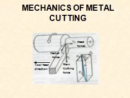
MECHANICS OF METAL CUTTING
(feed force)
Main Cutting force
Radial force
Tool feed direction
Slide2Topics to be covered
Tool terminologies and geometry
Orthogonal Vs Oblique cutting
Turning ForcesVelocity diagram
Merchants CirclePower
& Energies
Slide3Need for calculating forces, velocities and angles during machining??
We need to determine the cutting forces in turning for Estimation of cutting power consumption, which also enables selection of the power source(s) during design of the machine tools.
Structural design of the machine – fixture – tool system.
Evaluation of role of the various machining parameters (tool material and geometry) on cutting forces to make machining process more efficient and economical.
Condition monitoring of the cutting tools and machine tools.
Slide4Heat Generation Zones
(Dependent on sharpness
of tool)
(Dependent on
m
)
(Dependent on
f)
10%
30%
60%
Slide5Tool Terminology
Side relief
angle
Side cutting
edge angle
(SCEA)
Clearance or end
relief angle
Back
Rake
(BR),+
Side Rake
(SR), +
End Cutting
edge angle
(ECEA)
Nose
Radius
Turning
Cutting
edge
Facing
Cutting
edge
Slide6Cutting Geometry
Slide7Material Removal Rate
Slide8Metal cutting
Orthogonal
cutting
Oblique
cutting
Cutting Edge is normal to tool feed.
Here only two force components are considered i.e. cutting force and thrust force. Hence known as two dimensional cutting.
Shear force acts on smaller area.
Cutting Edge is inclined at an acute angle to tool feed.
Here only three force components are considered i.e. cutting force, radial force and thrust force. Hence known as three dimensional cutting.
Shear force acts on larger area.
Metal Cutting is the process of removing unwanted material from the workpiece in the form of chips
Slide9Assumptions
(Orthogonal Cutting Model)
The cutting edge is a straight line extending perpendicular to the direction of motion, and it generates a plane surface as the work moves past it.
The tool is perfectly sharp (no contact along the clearance face).
The shearing surface is a plane extending upward from the cutting edge.
The chip does not flow to either side
The depth of cut/chip thickness is constant uniform relative velocity between work and tool
Continuous chip, no built-up-edge (BUE)
Slide10Terminology
Slide11Terminology
α
: Rack angle
b
: Frictional angle
ϕ
: Shear angle
F
t
: Thrust Force
F
c
: Cutting Force
F
s
: Shear Force
F
n
: Normal Shear Force
F: Frictional Force
N: Normal Frictional Force
V: Feed velocity
Vc
: Chip velocity
Vs: Shear velocity
Slide12Forces
For Orthogonal Model
End view
Note: For the 2D Orthogonal Mechanistic
Model we will ignore the Longitudinal
component
12
Slide13Orthogonal Cutting Model
(Simple 2D mechanistic model)
Mechanism: Chips produced by the shearing process along the shear plane
a
t
0
f
+
Rake
Angle
Chip
Workpiece
Clearance Angle
Shear Angle
t
c
depth of cut
Chip thickness
Tool
Velocity V
tool
13
Slide14Orthogonal Cutting
14
Slide15tool
Cutting Ratio
(or chip thicknes ratio)
f
t
c
t
o
(f-a)
A
B
Chip
Workpiece
Slide16Experimental Determination of
Cutting Ratio
Shear angle
f
may be obtained
either from photo-micrographs
or assume volume continuity (no chip density change):
i.e. Measure length of chips (easier than thickness)
w
t
L
0
0
0
w
c
L
c
c
t
Slide17Shear Plane Length
and Angle
f
or make an assumption, such as
f
adjusts to minimize
cutting force:
(Merchant)
f
t
c
t
o
(f-a)
A
B
Chip
tool
Workpiece
Slide18Velocities
(2D Orthogonal
Model)
Velocity Diagram
(Chip relative
to workpiece)
V = Chip Velocity
(Chip relative to tool)
Tool
Workpiece
Chip
V
s
V = Cutting Velocity
(Tool relative to
workpiece)
Shear Velocity
c
a
f - a
90 - f
f
V
s
V
c
V
Slide19Cutting Forces
(
2D Orthogonal Cutting)
Free Body Diagram
Generally we know:
Tool geometry & type
Workpiece material
and we wish to know:
F = Cutting Force
F = Thrust Force
F = Friction Force
N = Normal Force
F = Shear Force
F = Force Normal to Shear
c
t
s
n
Tool
Workpiece
Chip
Dynamometer
R
R
R
R
F
c
F
t
f
s
F
F
n
N
F
19
Slide20F
s
, Resistance to shear of the metal in forming the chip. It acts along the shear plane.
F
n
, ‘Backing up’ force on the chip provided by the workpiece
. Acts normal to the shear plane.
N, It at the tool chip interface normal to the cutting face of the tool and is provided by the tool.
F, It is the frictional resistance of the tool acting on the chip. It acts downward against the motion of the chip as it glides upwards along the tool face.
Cutting Forces
(
2D Orthogonal Cutting)
20
Slide21F
n
F
t
Construction of merchant’s circle
F
s
F
c
F
R
α
α
φ
λ
φ
λ
-
α
N
V
Knowing
F
c
, F
t
,
α
and
ϕ
, all other component forces can be calculated.
Please note
l
is same as
b
in next slide = friction angle
21
Slide22Force Circle Diagram
(Merchants Circle)
R
F
t
F
c
Tool
F
N
a
b - a
b
a
a
F
s
f
b - a
f
F
n
22
Slide2323
Slide24Cutting Forces
Forces considered in orthogonal cutting include
Cutting, friction (tool face), and shear forces
C
utting
force,F
c acts in the direction of the cutting speed
V
, and supplies the energy required for cutting
Ratio of
F
c
to cross-sectional area being cut (i.e. product of width and depth of cut,
t
0
) is called:
specific cutting force
Thrust
force
,
F
t
acts in a direction normal to the cutting force
These two forces produces the resultant force,
ROn tool face, resultant force can be resolved into:
Friction force, F along the tool-chip interface
Normal force
,
N
to
to friction force
24
Slide25Cutting Forces
It can also be shown that (
is friction angle
)
R
esultant force, R
is balanced by an equal and opposite force along
the shear planeIt
i
s resolved into
shear force
,
F
s
and
normal force
,
F
n
Thus,The magnitude of
coefficient of friction,
is
25
Slide26Cutting Forces
The
toolholder
, work-holding devices, and machine tool must be stiff to support thrust force with minimal deflections
If Ft
is too high ⇒ tool will be pushed away from workpiecethis will reduce depth of cut and dimensional accuracy
The effect of rake angle and friction angle on the direction of
thrust force
isM
agnitude of the cutting force
,
F
c
is always positive
as the
force that supplies the work
is
required in cutting
However,
F
t
can be +ve
or –ve; i.e. F
t can be upward with a) high rake angle, b) low tool-chip friction, or c) both
26
Slide27Forces from
Merchant's
Circle
Slide28Stresses
On the Shear plane:
On the tool rake face:
Slide29Power
Power (or energy consumed per unit time) is the product of force and velocity. Power at the cutting spindle:
Power is dissipated mainly in the shear zone and on the rake face:
Actual Motor Power requirements will depend on machine efficiency E (%):
Slide30Material Removal Rate (MRR)
Slide31Specific Cutting Energy
(or Unit Power)
Energy required to remove a unit volume of material (often quoted as a function of workpiece material, tool and process:
Slide32Specific Cutting Energy
Decomposition
1. Shear Energy/unit volume (Us)
(required for deformation in shear zone)
2. Friction Energy/unit volume (Uf)
(expended as chip slides along rake face)
3. Chip curl energy/unit volume (Uc)
(expended in curling the chip)
4. Kinetic Energy/unit volume (Um)
(required to accelerate chip)
Slide33Cutting Forces and Power measurement
Measuring Cutting Forces and Power
Cutting forces can be measured using a
force transducer
, a dynamometer
or a load cell mounted on the cutting-tool holder
It is also possible to calculate the cutting force from the power consumption
during cutting (provided mechanical efficiency of the tool can be determined)
The specific energy (u
) in cutting can be used to calculate cutting forces
33
Slide34Cutting Forces and Power
Power
34
Prediction of forces is based largely on experimental data (right)
Wide ranges of values is due to differences in material strengths
Sharpness of the tool tip also influences forces and power
Duller tools require higher forces and power