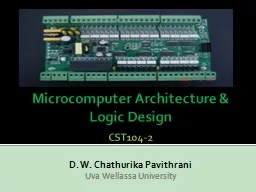
Lecture 27 Announcements Exams returned at end of lecture Homework 9 is up due Thursday 1211 Recitation quiz on Monday 128 Will cover material from Lectures 26 27 Agenda Last time Structure and Operation of Clocked Synchronous Sequential Networks 71 ID: 240440
Download Presentation The PPT/PDF document "Digital Logic Design" is the property of its rightful owner. Permission is granted to download and print the materials on this web site for personal, non-commercial use only, and to display it on your personal computer provided you do not modify the materials and that you retain all copyright notices contained in the materials. By downloading content from our website, you accept the terms of this agreement.
Slide1
Digital Logic Design
Lecture 27Slide2
Announcements
Exams returned at end of lecture
Homework 9 is up, due Thursday, 12/11
Recitation quiz on Monday, 12/8
Will cover material from Lectures 26, 27Slide3
Agenda
Last time:
Structure and Operation of Clocked Synchronous Sequential Networks (7.1)
Analysis of Clocked Synchronous Sequential Networks (7.2)
This time:
Modeling Clocked Synchronous Sequential Network Behavior (7.3)
State Table Reduction (7.4)Slide4
Modeling clocked synchronous sequential network behavior
Approach for the synthesis of clocked synchronous sequential networks:
State table/state diagram is constructed from word specifications.
State reduction technique to obtain a state table with minimum number of states.
Transition table is formed by coding the states of the state table.
Excitation table is constructed based on the flip-flop types to be used.
From the excitation table, the excitation and output expressions for the network are determined.
Finally, the logic diagram is drawn.Slide5
Examples of Modeling StepSlide6
State Diagram for
Mealy serial binary adderSlide7
State Diagram for
Moore serial binary adderSlide8
A Sequence Recognizer
An output of 1 is to be produced
iff
the three input symbols following two consecutive input 0’s include at least one 1.
At all other times the output is to be 0.
The output of 1 is to be coincident with the third input symbol of the three-input-symbol sequence.
Upon completing the analysis of the three input symbols
followin
the pair of 0 inputs, the network is to reset itself and await for another pair of 0’s and then at least one 1 in the following
seqence
of three input symbols.
Since the output is to be coincident with the third input symbol, a Mealy
netword
is implied.
Example:
x
=
0
1
0
0
0
1
0
0
1
0
0
1
0
0
1
0
0
0
0
0
0
0
0
1
1
z
=
0
0
0
0
0
0
1
0
0
0
0
0
0
1
0
0
0
0
0
0
0
0
0
0
1Slide9
A Sequence RecognizerSlide10
Another Sequence Recognizer
Network produces a 1 output
iff
the current input and the previous three inputs correspond to either 0110 or 1001
0110/1001 Sequence Recognizer
The 1 output is to occur at the time of the fourth input of the recognized sequence. Outputs of 0 are to be produced at all other times.
A Mealy network model is developed since the output is a function of the current input x.
Network is not required to reset upon the occurrence of the fourth input.
Sequences may overlap.
Example:
x
=
0
0
1
1
0
1
1
1
0
0
1
0
1
0
1
1
0
0
1
1
0
0
1
0
1
z
=
0
0
0
0
1
0
0
0
0
0
1
0
0
0
0
0
1
0
1
0
1
0
1
0
0Slide11
Another Sequence RecognizerSlide12
Final Example
Single input
and a single output
.
The output of the network is initially 0.
Changes on the next input immediately following each even occurrence of
.
The effect of the input is to be delayed by one clock period. The value of
during the next clock period does not affect the output of the network at that time.
A Moore sequential network is to be realized
Example:
x
=
0
0
1
1
0
0
0
1
0
1
0
1
1
1
0
a
b
c
z
=
0
0
0
0
1
1
1
1
1
1
0
0
0
1
1Slide13
Final Example
A: The output changes to 0 since the last occurrence of
was even
B: The output remains at 0 since the last occurrence of
was odd
C: The output changes to 1 since the last occurrence of
was even
D: The output remains at 1 since the last occurrence of
was odd
Slide14
State Table ReductionSlide15
State Table Reduction
The state table is a description of the terminal behavior of a clocked synchronous sequential network.
During the process of creating the state table, more states may be defined then are really necessary.
In analysis of synchronous sequential networks, bin codes for the states were replaced by arbitrary symbols when going from transition table to state table.
For synthesis, the opposite process is performed: Arbitrary state symbols are replaced with binary codes.
Smaller number of binary digits necessary -> smaller number of flip-flops.
Reducing number of states may also simplify the combinational logic.Slide16
State Table Reduction Procedure
3-step process:
Equivalent pairs of states are determined
Sets of equivalent states are established
Reduced state table is constructed with one state for each of the sets of equivalent statesSlide17
Determining Equivalent Pairs of States
Recall that given a state table, an input sequence and some starting state, the resulting output sequence can be determined.
Assume we run two experiments:
One starts in state p
The second starts in state qSlide18
Determining Equivalent Pairs of States
States
and
are said to be equivalent or indistinguishable
iff
for all input sequences applied to the two starting states, identical output sequences from both networks result
.
If states
and
are not equivalent, then they are said to be distinguishable
Slide19
Determining Equivalent Pairs of States
Theorem:
Two states
and
of a clocked synchronous sequential network are equivalent
iff
for each combination of values of the input variables
Their outputs are identical
Their next states are equivalent
Slide20
Determining Equivalent Pairs of States
Proof: First direction:
If the states are equivalent, then
for each combination of values of the input variables
Their outputs are identical
Their next states are equivalent
Assume there is some input combination such that outputs differ. Then clearly
Assume there is some input combination
such that next states
are distinguishable. Then by definition of distinguishable, there is some input sequence
for states
that produces different output sequences. Thus,
is a distinguishing input sequence for
and so
Slide21
Determining Equivalent Pairs of States
Proof: Second direction
If for each combination of values of the input variables
Their outputs are identical
Their next states are equivalent
Then the two states are equivalent.
Assume
are not equivalent. Then there is some input sequence
such that the outputs
and
differ. Assume that
are the pair of next states on this input.
If
then condition 1 is not satisfied.
If
, then
must be an input sequence such that the outputs
differ. Then
and condition 2 is not satisfied.
Slide22
Example of State Table in Which
State Reduction can be performed
No. Why not?
No. Why not?
Need to check
Circle back to
So yes,
.
Slide23
Algorithm for Determining Equivalent Pairs of States
Uses an
implication table
are the states of the state table. There is one cell in the implication table for each pair of distinct cells.
Slide24
Algorithm for Determining Equivalent Pairs of States
Place a
in the
-cell if the outputs are contradictory for some input. If there are no contradictory outputs then enter the pair of next states for each input. If neither a
nor pairs of states are entered in the cell, then a check mark is inserted (denoting equivalence of the two states).
All state pair entries are inspected by the following process:
If
is an entry in the
-cell and if the
-cell contains an
then an
is placed in the
the
-
cell and all other entries are ignored.
Otherwise, process is repeated on one of these other state pairs.
Repeat Step 2 until it is possible to make an entire pass of the implication table without any additional
being entered. If the
-cell has no
at this time, then
Slide25
Example of AlgorithmSlide26
Algorithm for Obtaining the Equivalence Classes of States
Starting with the rightmost column of the processed implication table and working toward the left, move to the first column that has a cell that does not contain a
. Write down the pairs of equivalent states for this column.
Move to the next column to the left, column
, which contains one or more non
cells. If state
is equivalent to all members of any set of states in the list, then add state
to the set. Otherwise, add to the list the pairwise equivalent states containing state
.
Repeat Step 2 until all columns are examined. Add to the list, as sets consisting of single states, any states that do not appear in one of the other sets in the list.
Slide27
Example for Implication Table
Slide28
Constructing the Minimal State Table
Original state table is
and minimal state table is
The set of states making up the equivalence classes are denoted
. The input columns for state tables
and
are the same and denoted
Assign a state
to each of the sets
for
The present state section of table
consists of
To determine the next-state entry in the
-row,
-column of table
:
Select any state in the set
. Use state table
to determine its next state for input
Next state is in some set
so table entry is
Output entries are determined similarly.
If the initial state of state table
is a member of
then
is the initial state of state table
Slide29
Constructing the Minimal State TableSlide30Slide31