
A board with a microcontroller and USB interface to a PC Large open source community Arduino Environment A development board 8bit microcontroller programming hardware USB programming interface ID: 1030686
Download Presentation The PPT/PDF document "The Arduino Platform A “development ..." is the property of its rightful owner. Permission is granted to download and print the materials on this web site for personal, non-commercial use only, and to display it on your personal computer provided you do not modify the materials and that you retain all copyright notices contained in the materials. By downloading content from our website, you accept the terms of this agreement.


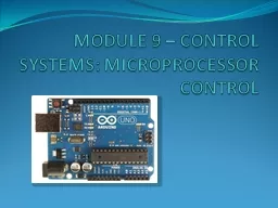


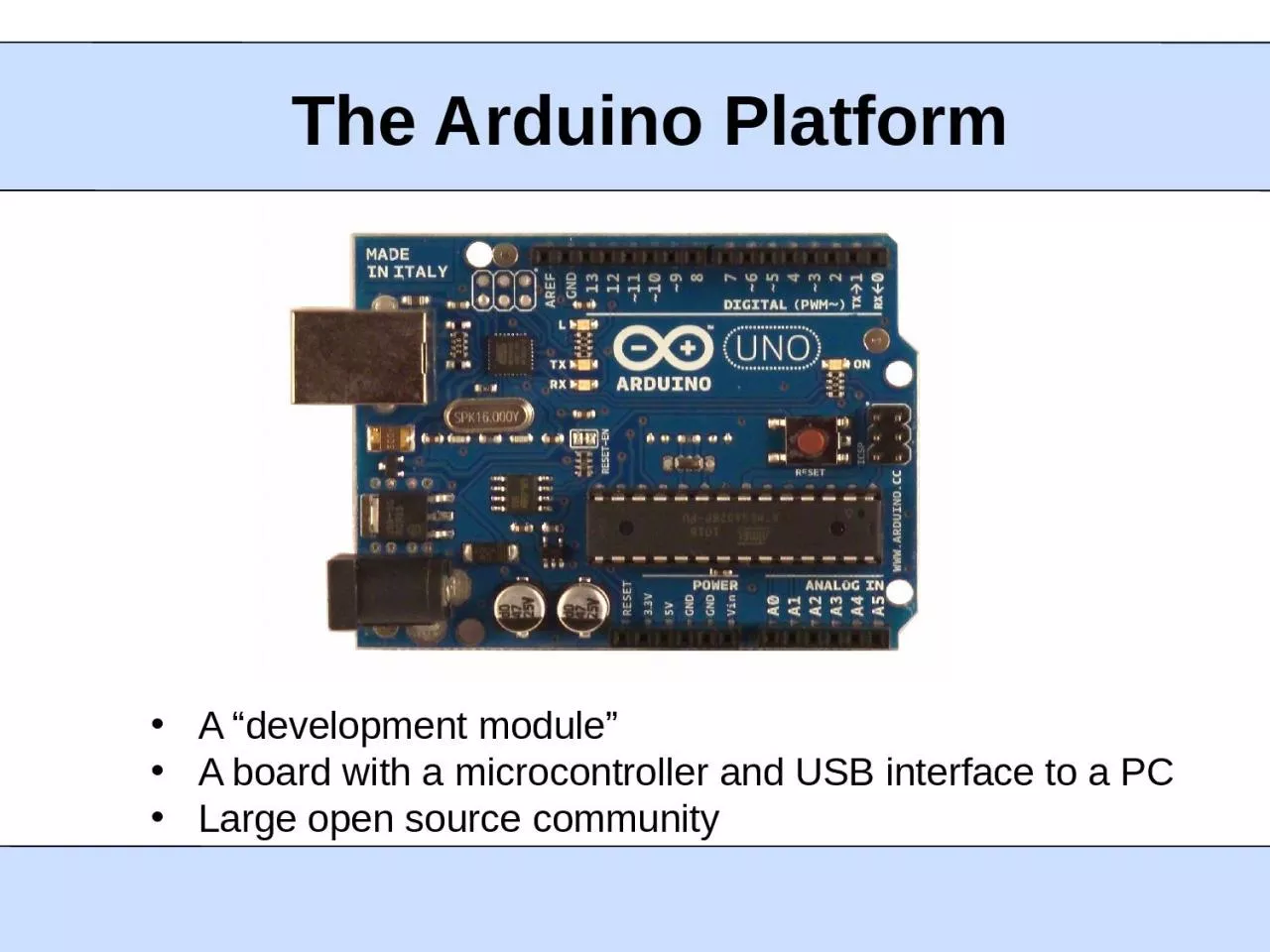
1. The Arduino PlatformA “development module”A board with a microcontroller and USB interface to a PCLarge open source community
2. Arduino EnvironmentA development board- 8-bit microcontroller- programming hardware- USB programming interface- I/O pinsA software environment- cross-compiler- debugger- simulator- programmerSpecial-purpose “shields”- daughter boards- unique functionalities- easy to attach- good libraries provided
3. Arduino HardwareMicrocontrollerATmega328Operating Voltage5VInput Voltage (recommended)7-12VInput Voltage (limits)6-20VDigital I/O Pins14 (of which 6 provide PWM output)Analog Input Pins6DC Current per I/O Pin40 mADC Current for 3.3V Pin50 mAFlash Memory32 KB (ATmega328) of which 0.5 KB used by bootloaderSRAM2 KB (ATmega328)EEPROM1 KB (ATmega328)Clock Speed16 MHzTypical of an 8-bit processor- low speed, low memory- low cost ($1.50 for the microcontroller, $40 for the board)
4. Raspberry Pi32-bit processorBroadcom BCM2838 SoC, ARM11700 MHz clock512 MB RAMBroadcom VideoCore IV GPUSD card slot, no flash built-inPorts: USB (2), HDMI, RCA audio/video, SD, Ethernet, 2x13 pinsMIPI Camera InterfaceSize of a credit card$35
5. Raspberry Pi Software32-bit machine, can support an operating systemArch linux, Debian, Fedora, Slackware, etc.A bit slow for developmentHard to run GUI, IDECross compile with crosstool-ng toolchain or gcc-linaro-arm-linuxEasy Python programming interface is available
6. BeagleBone BlackTI Sitara AM3359 ARM Cortex-A832-bit processor1 GHz clock512 MB RAM2GB on-board flash3D graphics acceleratorPorts: USB, Ethernet, HDMI, 2x46 pins$45 cost, almost the same as an Arduino
7. Beagle Software EnvironmentSeveral versions of linux are portedUbuntu, Angstrom, Android …A bit slow for developmentHard to run GUI, IDECross compile with gcc-arm toolchainBoneScript (JavaScript) library is provided for simplicityUses an interpreter
8. BeagleBone “Capes”Application-specific, stackable, daughter boardsJust like Arduino shieldsCome with librariesVGA CapeDVI-D CapeCamera Cape
9. Slides created by: Professor Ian G. HarrisUART/USARTUniversal Asynchronous Receiver/TransmitterUsed for serial communication between devicesUART is asynchronous, no shared clockAsynchronous allows longer distance communication Clock skew is not a problemUSART is the synchronous version of UARTCommon clock is neededNVIDIA® Tegra™ 250NVIDIA® Tegra™ 250
10. Slides created by: Professor Ian G. HarrisSerial ProtocolsData is transmitted seriallyOnly 1 bit needed (plus common ground)Parallel data transmitted seriallyOriginal bytes/words regrouped by the receiverMany protocols are serial to reduce pin usagePins are precious
11. Slides created by: Professor Ian G. HarrisUART ApplicationsUsed by modems to communicate with networkComputers used to have an RS232 port, standardNot well used anymore, outside of embedded systemsReplaced by USB, ethernet, I2C, SPISimple, low HW overheadBuilt into most microcontrollers
12. Slides created by: Professor Ian G. HarrisSimple UART StructureTxRxSerial OutSerial InParallel InParallel OutstatusstatusData is serialized by Tx, deserialized by RxStatus indicates the state of the transmit/receive buffersUsed for flow control
13. Slides created by: Professor Ian G. HarrisUART Timing DiagramFirst bit is the Start Bit, initiates the transferNext bits are the dataLast are the Stop Bits1 bit8 bits
14. Slides created by: Professor Ian G. HarrisBit DurationEach bit is transmitted for a fixed durationThe duration must be known to Tx and RxBaud Rate (f) determines the duration (T)Baud Rate is the number of transitions per secondTypically measured in “bits per second (bps)” T = 1/fEx. F = 9600 baud, T = ~104 microsecTransmission rate is less than baud rateNeed start bit, stop bits, parity bit
15. Slides created by: Professor Ian G. HarrisUART SynchronizationReceiver must know the exact start timeImprecise start time corrupts data01stopbit 7bit 8stopExpected Bit, correctExpected Bit, incorrectbit 7bit 8stop
16. Slides created by: Professor Ian G. HarrisStart Bit, SynchronizationDetection of the start bit is used to synchronizeSynchronization based on falling edge of start bitStart bit is a falling edge Following 0 must be long duration to screen out noiseReceiver samples faster than baud rate (16x typical)Start bit is indicated by a 0 of at least half periodJust a glitchStart bit detected
17. Slides created by: Professor Ian G. HarrisParity BitTransmission medium is assumed to be error-proneE-M radiation noise, synchronization accuracyParity bit may be transmitted to check for errorsEven Parity: Number of 1’s is evenOdd Parity: Number of 1’s is oddParity bit is added to ensure even/odd parityAfter data, before stop bit(s)Ex. Assume Odd Parity, Data = 011011010Parity bit = 0, total parity is odd
18. Slides created by: Professor Ian G. HarrisStop BitReceiver expects a 1 after all data bits and parity bitsIf 1 is not received, error has occurred1 bit8 bitsStop Bit
19. Slides created by: Professor Ian G. HarrisData Throughput vs. BaudEvery transmission involves sending signaling bitsStop, start, parityData throughput rate is lower than baud rateSignaling bits must be sentEx. 8 data bits, 1 parity bit, baud rate = 9600Send 11 bits to send 8 data bitsTransmission efficiency = 8/11 = 73%Data throughput rate = 9600 * 0.73 = 6981.8 bps
20. Slides created by: Professor Ian G. HarrisUSART HW in ATmegaTransmit PinReceive PinClock Pin For synchronous transfers Output (input) for master (slave)
21. Slides created by: Professor Ian G. HarrisClock GenerationTwo (or 3) clocks may be neededInternal Clock – Two internal clocksHigh speed clock used by receiver to sample incoming signal Slower baud rate clock used by transmitter to time transmissionExternal Clock – Only used in synchronous modeBaud rate clock used to synchronize master and slaveGenerated by master, read by slave
22. Slides created by: Professor Ian G. HarrisClock Generation LogicRx clk in generated from internal foscUBRRn – Prescalar value used to generate Rx clkUBRRn is two 8-bit registers, UBRRH and UBRRLInternal Tx ClkInternal Rx Clk
23. Slides created by: Professor Ian G. HarrisClock Operation ModesNormal AsynchronousRx/Tx clk rate is 16x baud rateAccurate sampling of signal, good synchronizationDouble Speed AsynchronousRx/Tx clk rate is 8x baud rateDouble speed transmission, less accurate synchronizationMaster SynchronousSynchronous communication, generate clkSlave SynchronousSynchronous communication, receive clk
24. Slides created by: Professor Ian G. HarrisSetting ClocksHigh Speed Internal ClockInternal Rate = fosc / (UBRRn + 1)Baud Rate Clk, Normal AsynchronousBaud = fosc / 16 (UBRRn + 1)Baud Rate Clk, Double Speed AsynchronousBaud = fosc / 8 (UBRRn + 1)
25. Slides created by: Professor Ian G. HarrisFrame FormatsUSART has several communication options to define how many bits are transmittedStart bit: 1Data bits: 5 – 9Parity bit: none, even, oddStop bits: 1 or 2Set using bits in the UCSRnB and UCSRnC registersFormat must match on both transmitter and receiver
26. Slides created by: Professor Ian G. HarrisUSART Register SummaryUBBR is the prescalar used to determine the clocksDetermines the BAUD rateUCSRA indicates the status of communicationsTransmit/Receive complete, errors, etc.UCSRB enables interrupts and communicationsInterrupt enable, Tx/Rx enable, data size, etc.UCSRC sets parity bits, stop bits, USART mode, ...UDR holds transmit data and received data
27. Slides created by: Professor Ian G. HarrisUCSRABit 7 – RXCn: USART Receive Complete Bit 6 – TXCn: USART Transmit CompleteBit 5 – UDREn: USART Data Register EmptyBit 4 – FEn: Frame ErrorBit 3 – DORn: Data OverRunBit 2 – UPEn: USART Parity Error
28. Slides created by: Professor Ian G. HarrisTypical USART Initialization#define FOSC 1843200// Clock Speed#define BAUD 9600#define MYUBRR FOSC/(16*BAUD)-1void main( void ){ USART_Init ( MYUBRR ); }void USART_Init( unsigned int ubrr){ /* Set baud rate */ UBRRH = (unsigned char)(ubrr>>8); UBRRL = (unsigned char)ubrr; /* Enable receiver and transmitter */ UCSRB = (1<<RXEN)|(1<<TXEN); /* Set frame format: 8data, 2stop bit */ UCSRC = (1<<USBS)|(3<<UCSZ0);} // USART_Init
29. Slides created by: Professor Ian G. HarrisTransmitting Datavoid USART_Transmit( unsigned char data ){ // Wait for empty transmit buffer while ( !( UCSRA & (1<<UDRE)) ); // Put data into buffer, sends the data UDR = data;}Data is transmitted by placing it in the UDR registerData Register Empty (UDRE) bit of the UCSRA registerSet to 0 while a transfer is going onNeed to wait for it before sending new data
30. Slides created by: Professor Ian G. HarrisReceiving Datavoid USART_Receive( void ){ // Wait for data to be received while ( !( UCSRA & (1<<RXC)) ); // Read data from UDRn buffer return ( UDR );}Data is received by reading it from the UDRn registerDifferent from transmit UDRn registerReceive Complete flag (RXC) bit of the UCSRA registerSet to 1 when new data is received
31. Slides created by: Professor Ian G. HarrisCommunicating with a PCNeed a Terminal Emulator program which “speaks” UART (serial)There are many free terminal emulatorsHyperterm (used to come with Windows)TermitePutty (which I use)Need to select a COM port to find the USB-to-serial adapterNeed to match frame format to the ATmega
32. Slides created by: Professor Ian G. HarrisPutty Terminal EmulatorCan communicate in several protocolsSelect “Serial”Fill in baud rateAdjust settings by selecting “Serial” in left column
33. Slides created by: Professor Ian G. HarrisPutty Serial SettingsFlow controlAtmega does not seem to support any
34. Slides created by: Professor Ian G. HarrisUART UsesUART may be an extra (slow) communication channelUseful if communication speed is not a problemDebuggingMake a “print” statementNote: will alter performance, but not muchSimple User InterfaceHumans are slow, interface can be as well
35. Slides created by: Professor Ian G. HarrisSynchronous CommunicationSynchronous protocols share a common clockMore accurate, faster than asynchronous protocolsSampling time is accurately knownRestricted to short range communicationClock edge and data must have identical timingClock edge must arrive at all receivers simultaneously
36. Slides created by: Professor Ian G. HarrisSynchronous ProtocolsUSARTLimited to communication between two devices (or broadcast)Serial Peripheral Interface (SPI)Multi-Drop Bus protocol, more than two devicesSingle master, many slavesInter-Integrated Circuit (I2C)Multi-drop, multi-master
37. Slides created by: Professor Ian G. HarrisSPIa.k.a Four Wire InterfaceMOSIMISOSCLKSS’MOSIMISOSCLKCS’MasterSlaveMaster Out Slave In (MOSI) –From Master to SlaveMaster In Slave Out (MISO) –From Slave to MasterSCLK – Clock generated by MasterSlave Select (SS’) – Indicates communication w/ selected slaveChip Select (CS’) – Alerts slave to communication
38. Slides created by: Professor Ian G. HarrisSPI Data TransmissionSerial transmission synchronized by the clockMany bytes may be sent in a single transfer8-bits is what we will useBi-directional data transmissionMOSI transmits concurrently with MISOInternal shift register may be used to hold both transmitted and received dataShift in a received bit, shift out a transmitted bit
39. Slides created by: Professor Ian G. HarrisClock Polarity and PhaseClock polarity and phase determine when data is made valid wrt the clockPolarity = 0 or 1, Phase = 0 or 1Data is valid on each clk rising edge or each clk falling edgeData valid edge (V) = PHASE XOR POLARITYPolarity = 0, Phase = 0: Rising edge samplingPolarity = 1, Phase = 1: Rising edge samplingPolarity = 0, Phase = 1: Falling edge samplingPolarity = 1, Phase = 0: Falling edge sampling
40. Slides created by: Professor Ian G. HarrisSPI Timing Diagramsbit1bit2bit3SCLKMOSISS’/CS’bit1bit2bit3SCLKMOSISS’/CS’Polarity, Phase = 0, 0 or 1, 1Polarity, Phase = 0, 1 or 1, 0
41. Slides created by: Professor Ian G. HarrisMultiple Independent SlavesNeed a unique SS’ for each slaveSlaveMOSIMISOSCLKSS1’SS2’SS3’MOSIMISOSCLKCS’MasterMOSIMISOSCLKCS’MOSIMISOSCLKCS’
42. Slides created by: Professor Ian G. HarrisSPI on the ATmegaOnly one SS’ lineSPDR Reading accesses last received transmissionWriting automatically sends a the dataDo not directly access the SPI pinsHandled in hardware