
Page 1of 6nBefore using theseinstructions it is helpful to watch this video screencast of the CAD drawing actually being done in the softwareClicktolinktothevideotutorialCube in a cubeFusion 360 tutor ID: 869572
Download Pdf The PPT/PDF document "WMGOutreachwarwickacuk" is the property of its rightful owner. Permission is granted to download and print the materials on this web site for personal, non-commercial use only, and to display it on your personal computer provided you do not modify the materials and that you retain all copyright notices contained in the materials. By downloading content from our website, you accept the terms of this agreement.

1 Page 1 of 6 WMGOutreach@warwick.ac
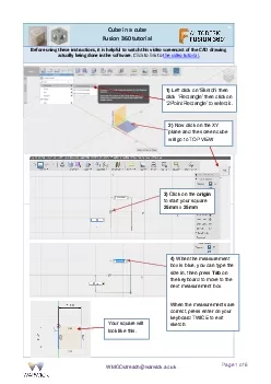
Page 1 of 6 WMGOutreach@warwick.ac.uk n Before using these instructions, it is helpful to watch this video screencast of the CAD drawing actually being done in the software . C l i c k t o l i n k t o t h e v i d e o t u t o r i a l . Cube in a cube Fusion 360 tutorial Your square will look like this . 3) Click on the origin to start your square 25 mm x 25 mm 4) When the measurement box is blue, you can type the size in, then press Tab on the keyboard to move to the next measurement box. When the measurements are correct, press enter on your keyboard TWICE to exit sketch. 1) Left click on ‘Sketch ’ then click ‘ Rectangle’ then click on
2 ‘2 Point Rectangle’ to select it.
‘2 Point Rectangle’ to select it. 2) Now click on the XY plane and the screen cube will go to TOP VIEW Page 2 of 6 WMGOutreach@warwick.ac.uk 5) Select CREATE Extrude (or E on keyboard) , click on the rectangle and the Extrude dialogue box appears. Either pull up the arrow to a height of 1 2 .5 mm or type 1 2 .5 in the box. Click OK to exit or just press Enter twice. Your shape should look like this. 6) Select MODIFY Shell, click on the top face of the box. Type 2 in the box to shell out the shape to a 2mm wall thickness. Press E nter to finish. 7) Select CREATE Mirror . In the Mirror dialogue box, ensure Bodies is selected and click on your shape to select it . Then click on Mirror Plane a
3 nd then select the top face of your sh
nd then select the top face of your shape and click OK. Page 3 of 6 WMGOutreach@warwick.ac.uk 8) You now need to Combine the 2 m irrored shapes into one object. Select MODIFY Combine In the Combine dialogue box, click on Target Body and select the top half of the object. Then click on Tool Body and select the bottom half of the object. Now click OK and your com bined shape will look like this – a hollow cube! 9) Next, cut the 15mm diameter holes through the side faces of the cube. Select SKETCH Centre Diameter Circle tool and select a face of the cube. Move the mouse around the cube face to find the centre point as here. Click on the centre and start drawing your 15mm diameter circle. When you have the correct me
4 asurement, click Enter twice to exit the
asurement, click Enter twice to exit the sketch. Your drawing will look like this. Page 4 of 6 WMGOutreach@warwick.ac.uk 10) Now use the Extrude tool to cut the hole. Press E on your keyboard to select Extrude tool, click on your circle sketch and then use the arrow to pull the through the shape to cut the hole – as above. Click OK and your drawing should look like this. 11) Repeat the process of drawing a 15mm circle then extruding the hole on 2 other sides as shown to the left. Your finished hollowed out cube should look like this. 12) Next select MODIFY Fillet and then left click on each of the 12 corner profiles to select them – they highlight blue when selected. Fillet by about 1.5mm and click OK as below .
5 Page 5 of 6 WMGOutre
Page 5 of 6 WMGOutreach@warwick.ac.uk 13) You now need to put a 12mm square cube exactly in the centre, inside the hollow cube. We will build the cube on an offset plane in the correct position inside the hollow cube. First select CONSTRUCT Offset Plane and click on the top face of the hollow cube. The plane must be moved down to the position where y ou need to bottom of the cube to sit. Use the diagram below to work out how far to move the offset plane and put the figure in the box and click OK and the plane will move to position. 2mm wall thickness 2mm wall thickness 12mm height of small cube 25mm Total height of big cube How big will each of these gaps be? – remember the total height of the cube is 25mm You need to move the offset plane down this distance ready to build the small cube on
6 to the plane, so that it sits in the mi
to the plane, so that it sits in the middle of the big cube Distance to move the offset plane is 2mm + ? mm + 12mm ? ? Page 6 of 6 WMGOutreach@warwick.ac.uk 14) Now draw the 12mm cube onto the offset plane. Select SKETCH Recta ngle Centre Rectangle, click the offset plane and you will go to TOP view as here. Now select the centre point to start sketch – make it 12mm x 12mm as above. When you have your 12mm x 12mm square sketch, press E on your keyboard to bring up the Extrude tool. Click on the 12mm x 12mm sketch to select it and put in a v alue 12mm to extrude it to make a 12mm square cube inside the box. Click OK when you have 12mm in the box. Your finished cube in a cube should look like t