
MINN KOTA ONBOARD BATTERY CHARGERSModels MK115PC MK230PC MK345PC MK460PCService InformationPlease call our service department at 18002276433 if you have any problems with your battery charg ID: 866396
Download Pdf The PPT/PDF document "OWNER146S MANUAL FOR" is the property of its rightful owner. Permission is granted to download and print the materials on this web site for personal, non-commercial use only, and to display it on your personal computer provided you do not modify the materials and that you retain all copyright notices contained in the materials. By downloading content from our website, you accept the terms of this agreement.


1 OWNER’S MANUAL FOR MINN KOTA ONBOA
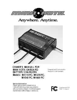
OWNER’S MANUAL FOR MINN KOTA ONBOARD BATTERY CHARGERS Models: MK115PC, MK230PC, MK345PC, MK460PC Service Information: Please call our service department at 1.800.227.6433 if you have any problems with your battery charger. A technical support representative will be happy to assist you. Compliant with FCC PART 15, Class A Designed and Constructed to Marine UL1236 Standard. 2 1) IMPORTANT SAFETY INSTRUCTIONS a) SAVE THESE INSTRUCTIONS! This manual contains important safety and operating instructions applicable to the safe and efficient use of your Minn Kota battery charger. b) The Minn Kota battery charger is a powerful electrical device. If incorrectly installed, configured or operated, the battery charger can damage batteries and / or electrical equipment. Please thoroughly read the instructions and safety information contained in this manual before operat- ing the battery charger. c) Use of an attachment not recommended or sold by Johnson Outdoors Inc. may result in risk of fire, electric shock, or injury to persons or prop- d) The charger is not intended for use by young children or infirm persons without supervision. Young children should be supervised to ensure that they do not play with the charger. e) To reduce risk of damage to electric plug or cord, pull by the plug rather than the cord when disconnecting the battery charger. f) An extension cord should not be used unless absolutely necessary. Use of the improper extension cord could result in a risk of fire or electric shock. If extension cord must be used, make sure: i) That pins of plug of the extension cord are the same number, size and shape of those of the plug on the battery charger; ii) That extension cord is properly wired and in good electrical condition; and iii) That wire in extension cord is proper size as follows: g) Do not operate the battery charger with a damaged cord or plug. h) Do not operate the battery charger if it has received a sharp blow, been dropped or otherwise
2 damaged in any way. i) Do not disassembl Do not disassembl")
damaged in any way. i) Do not disassemble the charger. Incorrect reassembly may result in a risk of electric shock or fire. j) To reduce risk of electric shock, unplug the charger from outlet before attempting any maintenance or cleaning. Disconnecting the leads will not reduce this risk. k) To reduce risk of shock or spark, never touch the ring terminals together while the charger is plugged into an outlet or extension cord. l) External connections to the battery charger shall comply with the United States Coast Guard electrical regulations (33CFR183, Sub Part 1). 2) PERSONAL PRECAUTIONS a) Consider having someone close enough nearby to come to your aid when you work near a lead acid battery. b) Have plenty of fresh water and soap nearby in case battery acid contacts skin, clothing or eyes. WARNING: RISK OF EXPLOSIVE GASES WORKING IN THE VICINITY OF A LEAD ACID BATTERY IS DANGEROUS. BATTERIES CONTAIN SULFURIC ACID AND PRODUCE EXPLOSIVE GASES. A BATTERY EXPLOSION COULD RESULT IN LOSS OF EYESIGHT OR SERIOUS BURNS. FOR THIS REASON, IT IS OF UTMOST IMPORTANCE THAT YOU FOLLOW THE INSTRUCTIONS EACH TIME YOU USE THE CHARGER. TO REDUCE THE RISK OF BATTERY EXPLOSION, FOLLOW THESE INSTRUCTIONS AND THOSE PUBLISHED BY THE BATTERY MANUFACTURER FOR ANY EQUIPMENT YOU INTEND TO USE IN THE VICINITY OF THE BATTERY. REVIEW CAUTIONARY MARKINGS ON THESE PRODUCTS AND ON ENGINE, MOTOR OR OTHER EQUIPMENT REQUIRING BATTERY USAGE. Minimum recommended AWG wire size for various length extension cords used with the Minn Kota battery charger: MK115PC Length of Cord in feet AWG Size AWG Size MK345PC Length of Cord in feet AWG Size AWG Size WARNING – DO NOT ATTEMPT TO REPAIR OR SERVICE THE CHARGER YOURSELF. OPENING THE CHARGER MAY EXPOSE YOU TO HIGH VOLTAGES, THE RISK OF ELECTRIC SHOCK, AND OTHER HAZARDS. c) Wear complete eye protection and clothing protection. Avoid touching eyes while working near battery. d) If battery acid contacts skin or clothing, wash immediately with s
3 oap and water. If acid enters eye, imme
oap and water. If acid enters eye, immediately flush eye with running cold water for at least 10 minutes and get medical attention immediately. e) Never smoke or allow a spark or flame in vicinity of battery, engine, motor or other flammable or explosive equipment. f) Be extra cautious to reduce risk of dropping a metal tool onto the battery or across the battery terminals. It might spark or short circuit the bat- tery or other electrical component that may cause an explosion. g) Remove personal metal items such as rings, bracelets, necklaces, and watches when working with a lead acid battery. A lead acid battery can produce a short circuit current high enough to weld such items, causing severe burns. h) Use the Minn Kota battery charger for charging and maintaining FLOODED LEAD-ACID, MAINTENANCE FREE, GEL CELL, AND AGM / STARVED ELECTROLYTE batteries only. It is not intended to supply power to low voltage electrical systems other than for charging and maintaining batteries. Do not use the charger for charging dry-cell batteries that are commonly used with home appliances. These batteries may burst and cause injury to persons and damage to property. i) NEVER charge a frozen battery. 3) PREPARING TO CHARGE a) If necessary to remove battery from boat or vehicle to charge or maintain, always remove grounded terminal from battery first (if applicable). Make sure all accessories in the boat or vehicle are off, so as not to cause an arc. b) Be sure area around battery is well ventilated while battery is being charged or maintained. c) Clean battery terminals. Be careful to keep corrosion from coming in contact with eyes. d) Add distilled water in each cell until battery acid reaches level specified by battery manufacturer. Do not overfill. For able cell caps, such as valve regulated lead acid batteries, carefully follow manufacturer’s recharging instructions. e) Study all battery manufacturers’ specific precautions while charging and for recommended rates of ch
4 arge. 4) CHARGER LOCATION AND MOUNTING a CHARGER LOCATION AND MOUNTING
a")
arge. 4) CHARGER LOCATION AND MOUNTING a) Locate charger as far away from battery as the dc cables permit. b) Never place charger above battery being charged; gases from battery will corrode and damage charger. c) Never allow battery acid to drip on charger when reading electrolyte specific gravity or filling battery. d) Do not operate charger in a closed-in area or restrict ventilation in any way. e) Do not set a battery on top of charger. f) Do not mount the charger below the waterline of the boat or directly adjacent to fuel tanks. g) Each DC output cord is six feet long. Make sure that all DC output cords can reach the batteries and that the AC power cord can reach a power source. practical to reduce the risk of a spark igniting gasses in the compartment. h) Each output cord is equipped with a temperature sensor. By monitoring external temperature, the battery charger adjusts the charging profile of the battery to assure full charge without overcharging or undercharging the battery. Attempting to shorten the output wires could damage the temperature sensor and affect the charger output. i) If the DC battery leads are not long enough, they may be lengthened by splicing and soldering 12 AWG (minimum) wire. Each splice should be covered with dual wall adhesive lined heat shrink tubing to protect the joint from corroding. The splice should be made between the sion length is 15 feet. You may contact the Minn Kota Service Department with any questions. Do not splice the AC power cord, as this voids the three year Limited Warranty. 3 j) Even though the Minn Kota charger is capable of operating in a high ambient temperature environment, a minimum of six inches of unobstruct- ed area should be allowed on all sides of the unit for proper air circulation and cooling. Proper cooling and circulation will operate at peak efficiency. k) MOUNTING THE CHARGER: Due to the weight of the charger and the impact that boats routinely endure, take the time to securely mount the
5 charger to Mounting with nuts, bolts an
charger to Mounting with nuts, bolts and washers is preferable to mounting with screws. Use the largest diameter bolts possible and use all four mount- ing holes. After marking the locations, set the charger aside and drill the holes. Apply a marine grade silicone sealant in each of the drilled holes to create a waterproof seal. Then secure the charger in place using the mounting hardware. l) Your battery charger is supplied with an AC plug holder designed to hold the power cord plug when not in use. Mount the AC plug holder with 5) DC CONNECTION PRECAUTIONS type of battery. b) The charger’s DC output terminals are designed to be permanently mounted and connected to batteries. c) Connect and disconnect DC output terminals only after disconnecting the AC plug from the electric outlet. d) The charger output leads must be connected with the correct polarity for the charger to function. The RED lead must be connected to the POSITIVE terminal of the battery and the BLACK lead must be connected to the NEGATIVE terminal of the battery, as indicated in e(5), e(6) and f(2), f(3). e) FOLLOW THESE STEPS WHEN THE BATTERY CHARGER IS INSTALLED IN A BOAT OR VEHICLE . A SPARK NEAR THE BATTERY MAY CAUSE BATTERY EXPLOSION. TO REDUCE THE RISK OF A SPARK NEAR THE BATTERY: 1) Position AC and DC cords to reduce risk of damage by hood, door, or moving engine parts. 2) Stay clear of fan blades, belts, pulleys and other parts that can cause injury to persons. 3) Check polarity of battery posts. POSITIVE (POS, P, +) battery post is usually larger in diameter than NEGATIVE (NEG, N, -) post. 4) Determine which post of the battery is grounded (connected) to the chassis (if any). If negative post is grounded to the boat hull or chassis (as in most vehicles), see (5) below. If positive post is grounded to the boat hull or chassis, see (6) below. If neither is grounded, the 5) For negative-grounded boat or vehicle, connect POSITIVE (RED) output terminal to POSITIVE (POS, P, +
6 ) ungrounded post of battery first. ungrounded post of battery
first.")
) ungrounded post of battery first. Then connect NEGATIVE (BLACK) output to NEGATIVE (NEG, N, -) grounded post of battery. 6) For positive-grounded boat or vehicle, connect NEGATIVE (BLACK) output to NEGATIVE (NEG, N, -) ungrounded post of battery first. Then, connect POSITIVE (RED) output terminal to POSITIVE (POS, P, +) grounded post of battery. 7) When disconnecting charger, disconnect AC power cord from electric outlet first. 8) See operating instructions for length of charge information. f) FOLLOW THESE STEPS WHEN BATTERY IS OUTSIDE BOAT OR VEHICLE . A SPARK NEAR BATTERY MAY CAUSE BATTERY EXPLOSION. TO REDUCE THE RISK OF A SPARK NEAR BATTERY: 1) Check polarity of battery posts. POSITIVE (POS, P, +) battery post is usually larger in diameter than NEGATIVE (NEG, N, -) post. 2) Connect POSITIVE (RED) output terminal to POSITIVE (POS, P, +) post of battery. 3) Connect NEGATIVE (BLACK) output terminal to NEGATIVE (NEG, N, -) post of battery. WARNING – MAKE SURE THE CHARGER IS DISCONNECTED FROM AC POWER BEFORE CONNECTING THE BATTERIES TO THE OUTPUT CORDS. CAUTION - Before making any connections to batteries in a confined space (such as a battery compartment of a boat), open the door or of the compartment and allow it to air out for 15 minutes. This allows any gasses that have accumulated in the compartment to escape. 4 CAUTION – Because the body of the battery charger is metallic, do not directly mount the charger to the hull of an aluminum boat. Use a means of isolation (such as wood or plastic) to prevent the charger body as well as mounting fasteners from coming in contact with the alumi - num boat structure or hull. Doing so will eliminate any risk of electrolysis that may occur when AC power is connected to the charger. 4) Do not face battery when making final connection. 5) When disconnecting charger, disconnect AC power cord from electric outlet first. 6) When disconnecting output terminals from battery posts, always do so in reverse sequence of t
7 he connecting procedure. 7) A marine (bo A marine (bo")
he connecting procedure. 7) A marine (boat) battery does not need to be removed and charged on shore. However, instructions must be followed for location of 6) GROUNDING AND AC POWER CORD CONNECTION INSTRUCTIONS The Minn Kota battery charger should be grounded to reduce risk of electric shock. The charger is equipped with an electric AC power cord with a grounded plug. The plug must be plugged into an outlet that is properly installed and grounded in accordance with all local codes and ordinances. 7) OPERATING INSTRUCTIONS types. It is important to read and understand how to properly use the battery charger before charging batteries. Each output bank is independent and isolated from one another and the AC input. The Minn Kota charger can charge independent batteries or combinations of batteries hooked in series or parallel without disconnecting the batteries from any switches or wires / straps joining the batteries. See diagram on page 10. INDICATOR LEDs: Each bank has the following LEDs: - Power On (GREEN). This LED is on anytime power is applied to the unit. - (RED): A steady RED LED indicates there is an issue with a connection. A flashing - 25%, 50%, 75% (YELLOW): These LEDs indicate the progress of charging. - 100% (GREEN): Flashing GREEN LED indicates battery is fully charged in Maintenance Mode and ready to use. Steady GREEN LED indi- cates battery is fully charged in long term Maintenance Mode and ready to use. MULTI-STAGE CHARGING: Minn Kota’s Multi-Stage Charging delivers a fast, precise charge profile by automatically controlling current and voltage without overcharging your batteries. Bulk Mode During this stage, the charger delivers full current until the battery reaches ~75% charge. Absorption Mode The charging current tapers down while the battery voltage is held constant (see Table 1 for voltages). Mild Equalize Mode (Flooded Lead-Acid Only) The voltage is automatically increased with each charging cycle for a maximum of 1.5 hours to d
8 esulfate and mix fluids in each battery.
esulfate and mix fluids in each battery. Equalize Mode (Flooded Lead-Acid Only) The equalize mode must be manually selected for each bank that is to be equalized. The voltage is increased hours to desulfate and mix fluids in each battery. Maintenance Mode When the battery reaches full charge, the charger voltage is reduced (see Table 1 for voltages). A flashing 100% GREEN LED is bank to indicate the battery is in Maintenance Mode and ready to use. After 24 hours, the charger automatically turns off and a steady 100% GREEN LED is lit for each bak to indicate the battery is in long term Maintenance Mode and ready to use. The charger will automatically turn on when the battery voltage drops below 12.6V. CAUTION - Due to the high charging current of the Minn Kota charger, it is recommended that each output be connected to only one battery. Connecting 2 output banks to one battery may cause excessive heating in the battery and could cause acid leakage or battery explosion. 5 CAUTION – To reduce risk of fire or electric shock, connect battery charger directly to grounding receptacle (three-prong). An adapter should not be used with battery charger. DANGER – Never alter AC cord or plug provided – if it will not fit outlet, have proper outlet installed by a qualified electrician. Improper con - nection can result in a risk of an electric shock. Table 1 6 Battery TypeAbsorptionEqualizeFloatFlooded Lead-Acid14.4V15.5V13.2V A 14.4Vn/a13.4V13.9Vn/a13.4V 7 Error Conditions: 1) A steady RED LED for each bank is lit if any of the following apply: a) No battery is connected to an output cord. This may also indicate a blown fuse in the fuse holder. b) The battery is connected reverse polarity. c) A short circuit. d) The battery voltage is below 4 volts. The bank will not charge a battery in this condition. (see note below) e) The battery voltage is above 16 volts. The bank will not charge a battery in this condition. 2) A flashing RED LED with steady 25%
9 YELLOW LED indicates the battery voltage
YELLOW LED indicates the battery voltage did not rise above 10.5V after 3 hours. The battery may be damaged and will not continue to be charged. 3) A flashing RED LED with steady 50% YELLOW LED indicates the charging in Bulk Mode exceeded 20 hours. The battery may be dam- aged and will not continue to be charged. 4) A flashing RED LED with steady 75% YELLOW LED indicates there is a damaged temperature sensor on the output cord. The bank will not operate if this occurs. 5) A flashing RED LED with steady 25% and 50% YELLOW LEDs indicates a fault within the charger. The bank will not operate if this Selecting Battery Type: The charger can be manually switched between 4 different modes; Gel Cell, Flooded Lead-Acid, AGM/High Performance AGM, and Equalize. In order to optimize the performance of your batteries or to prevent damage, you will need to properly set each charger bank for the correct bat - tery type (each bank can be independently set). The factory default setting is Flooded Lead-Acid. To set the battery type: 1) Plug the charger AC cord into an AC outlet. will indicate the current battery type. the button. The battery type will be saved even if the AC cord or DC output cords are disconnected. Flooded Lead-Acid batteries should be equalized per the battery manufacturers’ recommendations. Only Flooded Lead-Acid batteries should be equalized. The charger will only allow selection of the Equalize Mode if the previous selection was Flooded Lead-Acid. To set Equalize Mode, press and hold the Battery Selection button until all 3 YELLOW LEDs are lit, then release the button. Once in Equalize Mode, the equalize pro - cess will only be performed one time. Once this cycle is completed or if the cycle is interrupted (by unplugging the AC or a DC cord) the char - ger will revert back to the Flooded Lead-Acid battery type. General Operation: After the AC cord on the charger is plugged in and a battery is connected to the output cable correctly, the 25%
10 charging LED will turn on. After 2 se
charging LED will turn on. After 2 seconds the charger will begin charging the battery. The 2 second delay is added to allow the user to establish a good connection before the charger output is turned on. This will help prevent unwanted sparks during battery connections. The YELLOW LEDs will indicate how far the charger is in the charging process. Once the 100% GREEN LED is flashing, the charger is holding the battery in Maintenance Mode. The char - ger will stay in Maintenance Mode for 24 hours. After 24 hours in the Maintenance Mode, the charger output will turn off and the 100% GREEN LED will switch to steady GREEN. INLINE FUSE: Each output cord has inline fuses on the RED and BLACK leads located near the ring terminals. These fuses serve as protection and short circuits caused by a damaged charger output cable. If a fuse blows, replace it with the exact type and rating of the original fuse. Improper battery connections will normally not cause a fuse to blow since this is handled by the internal circuitry of the charger. WARNING – TO REDUCE RISK OF ELECTRIC SHOCK, DO NOT PERFORM ANY SERVICING OTHER THAN THOSE CONTAINED IN THE OPERATING INSTRUCTIONS. CAUTION – Generators with a modified square wave output can damage this MINN KOTA charger. Generators with a sine wave output can be used to power this charger. CAUTION – We recommend that you not recharge your battery, (or batteries), with the watercraft or motor lower unit in the water during electrical storms. Severe damage to the motor or charging system may occur if lightning strikes nearby or if storm related high voltage conditions exist. NOTE – A 12 volt battery with an open-circuit voltage below 4 volts has either been discharged to the point of internal damage, may be heavily sulfated, or may have internal shorted cells. Attempting to charge a battery in this state is dangerous. The battery should be replaced. WARNING – Battery type is factory preset for Flooded Lead-Acid. If y
11 ou are using alternate type batteries, s
ou are using alternate type batteries, select Gel or AGM/High Performance AGM. Failure to do so could result in damage to your battery and/or cause acid leaks. CAUTION – If a RED LED is flashing, disconnect the AC power from the charger immediately. Determine the reason based on the above information and take the necessary corrective action to remedy the situation. If you are unable to remedy the situation and need help, call the Minn Kota Service Department at 1.800.227.6433 and a technical support representative will be happy to assist you . 8) MAINTENANCE / CLEANING / STORAGE INSTRUCTIONS Check battery charger for dirt, oil, battery corrosion, etc. Use a water and baking soda solution for cleaning corrosion. Wipe clean using a dry cloth. Check ring terminals for dirt, oil, and battery corrosion; then disconnect from battery posts and clean as necessary with solution and dry with a clean cloth. When the charger is not in use, coil the power cord to prevent damage. If power cord or plug becomes damaged, you may contact the Minn Kota Service Repair Department for service repair information. Otherwise, dispose of the battery charger in compliance with local law. Damaged cords and plugs can cause electric shock or electrocution. When storing the battery charger, store in a clean dry area. FCC Class A EMC Notice NOTE – This equipment has been tested and found to comply with the limits for a Class A digital device, pursuant to part 15 of the Rules. These limits are designed to provide reasonable protection against harmful interference in a commercial installation. This equipment generates, uses and can radiate radio frequency energy and, if not installed and used in accordance with the instructions, may interference to radio communications. However, there is no guarantee that interference will not occur in a particular installation. If this equip - ment does cause harmful interference to radio or television reception, which can be determined by turning the
12 equipment off and on, the user is enco
equipment off and on, the user is encouraged to try to correct the interference by one or more of the following measures: Reorient or relocate the receiving antenna. Increase the separation between the equipment and receiver. Connect the equipment into an outlet on a circuit different from that to which the receiver is connected. Consult the dealer or an experienced radio/TV technician for help. CAUTION – Changes or modifications not expressly approved by the party responsible for compliance could void the user’s authority to oper - ate the equipment. 8 9) TROUBLESHOOTING PROBLEM: RED LED is lit. SOLUTION: -Check polarity of leads to battery. -Check connections to battery and fuses in output cord. -Check voltage at battery. The bank will not charge a battery below 4 volts or above 16 volts. -If still not working, call the Minn Kota Service Department at 1-800-227-6433. PROBLEM: RED LED is flashing with steady 25% YELLOW LED. SOLUTION: -Check to make sure there are no power loads on the battery -Check the fluid in the battery and add fluid per battery manufacturer’s specifications. -If the voltage of the battery does not increase above 10.5 volts after 3 hours, then the bank will shut down and will not char -If still not working, call the Minn Kota Service Department at 1-800-227-6433. PROBLEM: RED LED is flashing with steady 50% YELLOW LED. SOLUTION: -Check to make sure there are no power loads on the battery -Check the fluid in the battery and add fluid per battery manufacturer’s specifications. ot charge. The battery should be tested. -If still not working, call the Minn Kota Service Department at 1-800-227-6433. PROBLEM: RED LED is flashing with steady 75% YELLOW LED. SOLUTION: -The temperature sensor in the output cord is damaged. If the output cord was extended, check to make sure the procedure in th followed. -If still not working, call the Minn Kota Service Department at 1-800-227-6433. PROBLEM: RED LED is flashing with steady 25% and 50% YELLO
13 W LEDs. SOLUTION: -There is a fault with
W LEDs. SOLUTION: -There is a fault within the charger. -Reset the charger by unplugging the AC cord. Wait for all LEDs to turn off. -Plug in the AC cord. -If still not working, call the Minn Kota Service Department at 1-800-227-6433. PROBLEM: Indicator lights will not illuminate. SOLUTION: -Check the AC power at the outlet. -Make sure the GFCI(Ground Fault Circuit Interrupter) for the outlet has not tripped. -If an extension cord is being used, check the AC power at the end of the extension cord. -If still not working, call the Minn Kota Service Department at 1-800-227-6433. Specifications: Model Part No. System Volts Banks Output per Bank (amps) Total Output (amps) Input Cable Output Cable Size L x W x H Weight (lbs) Input Cu rrent (120VAC, 60Hz) MK115PC 1821151 12 1 15 15 18AWG - 6’ 12AWG - 6’ 6-3/4” x 10” x 3-3/4” 5.3 3.5A MK230PC 1822301 12 / 24 2 15 30 16AWG - 6’ 12AWG - 6’ 9-1/2” x 10” x 3-3/4” 8.8 7A MK345PC 1823451 12 / 24 / 36 3 15 45 14AWG - 6’ 12AWG - 6’ 13” x 10” x 3-3/4” 12.4 10.5A MK460PC 1824601 12 / 24 / 36 / 48 4 15 60 12AWG - 6’ 12AWG - 6’ 16” x 10” x 3-3/4” 15.8 14A 9 If batteries are connected in series for 12/24 - 24V, the series connection wire can be left in place during charging. If batteries are connected in series for 12/24 - 24 - 24/36 - 36V, the series connection wire can be left in place during charging. If batteries are connected in series for 12/24 - 24 - 24/36 - 36V- 36/48 - 48v, the series connection wire can be left in place during charging. 12v battery RED+ 120V AC INPUTBLACK-TWO BANK BATTERY CHARGER 12v battery RED+ BLACK- 12v battery RED+ 120V AC INPUTBLACK-THREE BANK TTERY CHARGER 12v battery RED+ BLACK- 12v battery RED+ BLACK- 12v battery RED+ 120V AC INPUTBLACK-FOUR BANK BATTERY CHARGER 12v battery RED+ BLACK- 12v battery RED+ BLACK- 12v battery RED+ BLACK- 12v battery RED+ 120V AC INPUTBLACK- SINGLE BANK BATTERY CHARG