
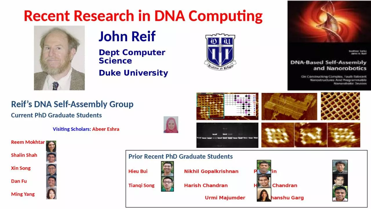
John Reif Dept Computer Science Duke University Prior Recent PhD Graduate Students Hieu Bui Nikhil Gopalkrishnan Peng Yin Tianqi Song Harish Chandran Harish Chandran Urmi Majumder Sudhanshu Garg ID: 927907
Download Presentation The PPT/PDF document "Recent Research in DNA Computing" is the property of its rightful owner. Permission is granted to download and print the materials on this web site for personal, non-commercial use only, and to display it on your personal computer provided you do not modify the materials and that you retain all copyright notices contained in the materials. By downloading content from our website, you accept the terms of this agreement.


Slide1
Recent Research in DNA Computing
John ReifDept Computer ScienceDuke University
Prior Recent PhD Graduate Students
Hieu Bui
Nikhil
Gopalkrishnan
Peng Yin
Tianqi Song
Harish Chandran Harish Chandran
Urmi Majumder Sudhanshu Garg
Reif’s
DNA Self-Assembly Group
Current PhD Graduate Students
Visiting Scholars:
Abeer Eshra
Reem
Mokhtar
Shalin
Shah
Xin SongDan FuMing Yang
Slide2Organization of Talk
Localized DNA Computation:
Faster and Simpler Molecular-Scale Computing
Programming DNA-based Biomolecular Reaction Networks on Cancer Cell Membranes: localized circuits, molecular reaction networks
Compact and Fast DNA Logic Circuits Using Strand-Displacing Polymerase and Single-Stranded Logic Gates: logic circuits, enzyme-based circuits
DNA-based Analog Computing: analog circuits
2
Slide3Localized DNA Computation
Hieu
Bui and John Reif
Linear Cascade DNA Hybridization Chain Reactions (in solution, not localized)
Localized DNA Hybridization Chain Reactions on DNA Tracks
Localized DNA Hybridization Chain Reactions on DNA Origami3
Slide4Localized DNA Computation
[Hieu Bui and John Reif]Hieu Bui,
Sudhanshu Garg, Reem
Mokhtar, Harish Chandran, Vincent Miao and John Reif, Design and Analysis of Localized DNA Hybridization Chain Reactions, Small (2017), 1602983. DOI: 10.1002/smll.201602983 Hieu Bui, Sudhanshu Garg, Vincent Miao, Tianqi Song, Reem Mokhtar
, and John Reif, Design and Analysis of Linear Cascade DNA Hybridization Chain Reactions Using DNA Hairpins, Special Issue, Journal of New Physics, Vol. 19, (2017) 015006. doi:10.1088/1367-2630/aa53d0 Hieu Bui, Shalin Shah, Reem Mokhtar, Tianqi Song, Sudhanshu Garg
, John Reif, Localized DNA Hybridization Chain Reactions on DNA Origami, ACS Nano, Volume 12, Num. 2, pp 1146–1155(January 22, 2018). DOI: 10.1021/acsnano.7b06699259.Hieu Bui and John H Reif, Localized DNA Computation, Chapter 19 in book: “From Parallel to Emergent Computing” (Edited by Andrew
Adamatzky, Selim
Akl, and Georgios
Ch. Sirakoulis), CRC Press (February 18, 2019). Taylor & Francis Group of CRC Press. ISBN: 9781138054011 Sudhanshu Garg, Hieu Bui, Abeer Eshra, Shalin Shah and John H Reif, Nucleic Acid Hairpins: A Robust and Powerful Motif for Molecular Devices, Chapter 7 in book: “Soft Nanomaterials” (Edited by Ye Zhang), World Scientific, (2019).
4
Slide5Motivations
DNA – programmable, predictable, and self-assembly.DNA circuits (AND, OR, NOT, etc.) – versatile, inexpensive, capable of parallel computing.The locality effect may speedup the reactions.Faster switching time compared to regular DNA hybridization reactions.Minimal leakages due to the physical constraints.Reusable sequences (gates) - scalable
5
B-DNA (10.5bp, 0.34nm/
bp, 2nm diameter)
Slide6Autonomous reaction of controlled self-assembly.
Hairpins 1–9 are stable in the absence of initiator I.The initiator binds at the sticky end of H1 and undergoes an unbiased strand displacement interaction to open the hairpin. The newly exposed sequestered sticky end of H1 binds to the external sticky end of H2 and opens the hairpin to expose a sequestered sticky end on H2.
This cascade reaction continues until H9 is opened.The designed product is a linear chain formed by staggered hybridization of nine hairpins.
Components of the linear cascade DNA hybridization chain reaction system consisting of 9 metastable DNA hairpins.
Hieu Bui, Sudhanshu Garg, Vincent Miao, Tianqi Song, Reem Mokhtar, John Reif 2017 New J. Phys. 19 015006
6
Linear Cascade DNA Hybridization Chain Reactions (in solution, not localized)
Slide7Linear Cascade DNA Hybridization Chain Reactions (in solution, not localized)
Simulation results of various linear cascade reaction lengths. The length depends on the number of hairpins involved in each reaction. Simulation conditions are specified as the following: 5 nM concentration of hairpins, 6.5 nM concentration of reporter complex, 10 nM concentration of initiator, and the rate constant of displacing the reporter complex is common across all simulation experiments.
Linear cascade reactions when the rate constant is 105
M−1 s−1 (A) versus 1.3 × 10⁶ M−1 s−1 (B). Simulation is performed based on the assumption that all hairpin–hairpin pairs follow the second order(bimolecular) chemical reaction.
(A)(B)
7Hieu Bui, Sudhanshu Garg, Vincent Miao, Tianqi Song, Reem Mokhtar, John Reif 2017 New J. Phys. 19 015006
Slide8Linear Cascade DNA Hybridization Chain Reactions (in solution, not localized)
Native PAGE gel of different linear cascade reactions involving 2 hairpins with and without addition of target DNA initiator. (A)Native PAGE gel of different linear cascade reactions involving 4 hairpins with and without addition of target DNA initiator. (B)Native PAGE gel of different linear cascade reactions involving 6 hairpins with and without addition of target DNA initiator. (C)
A
BC
8Hieu Bui, Sudhanshu Garg, Vincent Miao, Tianqi Song, Reem Mokhtar, John Reif 2017 New J. Phys. 19 015006
Slide9Linear Cascade DNA Hybridization Chain Reactions (in solution, not localized)
Kinetic characterization of the linear cascade DNA hybridization chain reactions. All samples were prepared at 5 nM of hairpin with 6.5 nM of reporter complex.(A) Schematic of LCR system before and after interacting with the reporter complex.(B) Effect of initiator concentration on the rate of linear cascade reaction. Hairpins do not hybridize in the absence of initiator(9 hairpins + 0× I, black). The linear cascade reaction occurs in the presence of 1× initiator concentration (9 hairpins + 1× I, red). The linear cascade reaction occurs at the same rate in the presence of excess initiator(9 hairpins + 8× I, green).
(C) Effect of hairpin concentration on the rate of crosstalk and leak reactions: 5 nM (black curve), 25 nM (red curve), and 50 nM (green curve)without the presence of initiator.
A
B
CHieu Bui, Sudhanshu Garg, Vincent Miao, Tianqi Song, Reem Mokhtar, John Reif 2017 New J. Phys. 19 015006
9
Slide10Linear Cascade DNA Hybridization Chain Reactions (in solution, not localized)
Effect of the number of hairpins on the rate of linear cascade reaction: 1 hairpin (black curve), 2 hairpins(red curve), 4 hairpins(green curve), 6 hairpins(blue curve), 9 hairpins(cyan curve). Note: the dotted horizontal line indicates the half-life of the linear cascade reaction (the time required for the reaction to reach 50% completion). Inset shows the real-time kinetic of all linear cascade reactions at equilibrium.
Empirical projection of the half-time completion as a function of hairpins. Note: each circle is an experimental result corresponding to the number of hairpins participating in the linear cascade reaction; a blue line is a fitted curve from those circles.
10
Hieu Bui, Sudhanshu Garg, Vincent Miao, Tianqi Song, Reem Mokhtar, John Reif 2017 New J. Phys. 19 015006
Slide11Localized DNA Hybridization Chain Reactions on DNA Tracks
Components of localized DNA hybridization chain reaction system: six metastable DNA hairpins anchored to a long DNA track via Ai domains. Prior to the addition of the initiator, DNA hairpins do not hybridize and are sequestered in the inactive states. Triggered self-assembly of localized DNA hybridization chain reaction mechanism for the first and last steps upon sensing the presence of the catalyst / initator.
Bui, H., Miao, V., Garg, S., Mokhtar, R., Song, T., Reif, J.,
Small
2017, 13, 1602983.11
Slide12Localized DNA Hybridization Chain Reactions on DNA Tracks
Fluorescence reporting mechanism to observe the kinetics of localized DNA hybridization reaction. A FRET pair consists of a fluorescence donor (green) and a fluorescence quencher (black). Upon sensing the completion, the FRET pair is disrupted by the last hairpin, giving rise to an increase in the fluorescence emission.
Bui, H., Miao, V., Garg, S., Mokhtar, R., Song, T., Reif, J.,
Small 2017, 13, 1602983.
12
Slide13Localized DNA Hybridization Chain Reactions on DNA Tracks
Kinetic characterization of triggered self-assembly hybridization chain reactions.A) Localized DNA hybridization chain reactions with and without the presence of the long DNA track in two times excess initiators. Note: inset shows the fluorescence responses of the same systems but in the absence of the initiator. B) Effect of localized DNA hybridization chain reaction rate as a function of initiator concentration. C) Control kinetic analysis of reactions as a function of hairpins in the absence of long DNA track.
C
Bui, H., Miao, V., Garg, S., Mokhtar, R., Song, T., Reif, J., Small 2017, 13, 1602983.
13
AB
Slide14Localized DNA Hybridization Chain Reactions on DNA Tracks
Fluorescence experimental results of the two systems which are then used to quantify the speed-up from tethering DNA hairpins on the DNA track: A) six DNA hairpins (no anchor domain, no track) in the presence of 2× initiatorsB) six DNA hairpins bound to the long DNA track in the presence of 2× initiators. Note: Dashed lines indicate half-time completion—the time required for the reaction to reach 50% completion.C) Model to describe cascade reactions with and without the locality effect. Note: AND symbol indicates bimolecular reaction; TRIANGLE symbol indicates unimolecular reaction
Bui, H., Miao, V., Garg, S., Mokhtar, R., Song, T., Reif, J.,
Small 2017, 13, 1602983.
14
Slide15Localized DNA Hybridization Chain Reactions on DNA Origami
DNA origami rectangle with modified staple strands (green circles). Metastable DNA hairpins tethering to DNA origami rectangle’s surface via modified staple strands through the anchor domains.
Mechanism of DNA hybridization reactions on DNA origami surface. Metastable DNA hairpins tethering to DNA origami rectangles via modified staple strands. Upon sensing the presence of the target initiator, the chain reactions occur among the hairpins, releasing the encoded information in the last hairpin.
Hieu Bui, Shalin Shah, Reem Mokhtar, Tianqi Song, Sudhanshu Garg, and John Reif
ACS Nano
2018
12
(2), 1146-1155
15
Slide16Localized DNA Hybridization Chain Reactions on DNA Origami
AFM images of DNA origami rectangle labeled with DNA hairpins.Six metastable DNA hairpins self-assembled on DNA origami rectangle (a)Six metastable DNA hairpins underwent cascade hybridization reactions after adding the initiator (b)Six metastable DNA hairpins underwent cascade hybridization reactions after adding the biotin-labeled output to detect the reaction completion via binding to the streptavidin molecule (c)
Hieu Bui, Shalin Shah, Reem Mokhtar, Tianqi Song, Sudhanshu Garg, and John Reif
ACS Nano 2018
12 (2), 1146-115516
Slide17Localized DNA Hybridization Chain Reactions on DNA Origami
(a) Illustration of DNA origami used single-molecule TIRF experiment. Blue tokens indicate hairpins while red token indicates marker strand.(b, c) TIRF images for DNA origami labeled with ATTO 647N marker and TAMRA initiator. The green channel is for 561 nm laser line (TAMRA label). Similarly, the red channel is for 635 nm laser line (ATTO 647N label). The approximate Gaussian localized images for both the channels. These images are analyzed for co-localization independent of the dynamic range values and noise. (d) Co-localized image where yellow spots (highlighted in green boxes) representing DNA origami with hairpins.Scale bars are 5 μ
m.
Hieu Bui, Shalin Shah, Reem Mokhtar, Tianqi Song, Sudhanshu Garg, and John Reif ACS Nano 2018
12 (2), 1146-115517
Slide18Localized DNA Hybridization Chain Reactions on DNA Origami
a) Illustration of DNA origami used single-molecule TIRF experiment. Blue tokens indicate hairpins while red token indicates marker strand.(b, c) TIRF images for DNA origami labeled with ATTO 647N marker dye and ATTO 488 output. The blue channel is for 488 nm laser line (ATTO 488 label). Similarly, the red channel is for 635 nm laser line (ATTO 647N label). The approximate Gaussian localized images for both the channels. (d) Co-localized image where yellow spots (highlighted in green boxes) indicates DNA origami with reaction completion. (e) Co-localization analysis for different reaction incubation times to observe kinetics. Scale bars are 5
μm.
Hieu Bui, Shalin Shah, Reem Mokhtar, Tianqi Song, Sudhanshu Garg, and John Reif ACS Nano 2018
12 (2), 1146-115518
Slide19Localized DNA Hybridization Chain Reactions on DNA Origami
(a) Schematic of localized cascade DNA hybridization chain reaction on the surface of DNA origami rectangle before and after the completion. (b) Kinetic characterization of localized cascade DNA hybridization chain reaction on DNA origami rectangle (green curve). Kinetic characterization of cascade DNA hybridization chain reaction without DNA origami rectangle (purple curve). Each solution was kept at 5 nM concentration and the initiator was added in 2× excess. (c) Effect of localized cascade DNA hybridization chain reaction rate as a function of initiator concentration.
Hieu Bui, Shalin Shah, Reem Mokhtar, Tianqi Song, Sudhanshu Garg, and John Reif
ACS Nano 2018
12 (2), 1146-115519
Slide20Summary of Localized Linear Cascade Results
Design, simulation, and synthesis of linear cascade DNA hybridization chain reactions.9 distinct hairpins underwent cascade hybridization chain reactions upon sensing the presence of the target initiator.Design, simulation, and synthesis of linear cascade DNA hybridization chain reactions on DNA tracks.6 distinct hairpins underwent cascade hybridization chain reactions
The speedup was observed due to the locality effect.Design, simulation, and synthesis of linear cascade DNA hybridization chain reactions on DNA origami.
6 distinct hairpins underwent cascade hybridization chain reactionsThe speedup was observed due to the locality effect, consisting with prior studies.Proof-of-concept examples which can be applied to other surfaces to utilize the locality effect.Combination with other DNA circuits to carry out surface DNA computation. 20
Slide21Organization of Talk
Localized DNA
Computing
Programming DNA-based Biomolecular Reaction Networks on Cancer Cell Membranes
Compact and Fast DNA Logic Circuits Using Strand-Displacing Polymerase and Single-Stranded Logic GatesDNA-based Analog Computing
21
Slide22Programming DNA-based Biomolecular Reaction Networks on Cancer Cell Membranes
Tianqi
Song and John Reif
22
Tianqi Song,
Hieu Bui, Sudhanshu
Garg,
Abeer Eshra
, Daniel Fu, Shalin
Shah, Ming Yang,
Reem Mokhtar, and John Reif, Programming DNA-Based Biomolecular Reaction Networks on Cancer Cell Membranes, submitted for publication(2019)
Slide2323
initiator
DNA-based Biomolecular Reaction Networks on Cancer Cell Membranes
D
DNA strand
displacement reactions
output
Song et al. (2019) In submission
Slide2424
Goals, Principles and Solutions
Song et al. (2019) In submission
Slide25Node Design
25
Two modules: reaction module (DNA hairpin) and addressing module.
Two modules are paired by the hybridization between domains A and A*.
sgc4f is an aptamer to target a particular cell membrane receptor.
DNA strand
displacement reaction
Song et al. (2019) In submission
Slide26Cascade Reaction
26
sgc4f
sgc8c
output
initiator
Abstraction:
Song et al. (2019) In submission
Slide27Capability and Applications
Linear cascades
Complex reaction networks
Logic circuits
Cancer cell recognition and therapies
27
Song et al. (2019) In submission
Slide28Linear Cascades
CCRF-CEM
Ramos
sgc4f
sgc8c
TC01
sgc4f
sgc8c
TD08
TC01
TE13
TD08
TC01
Flow cytometry results: high ratios (in fluorescence intensity) between Cell
with circuit
and Cell
only
(data from three repeats).
28
Cancer Cell Lines:
Song et al. (2019) In submission
Slide29A Reaction Network
on CCRF-CEM
29
sgc4f
sgc8c
TC01
TE13
TE17
TC01
sgc4f
sgc8c
TC01
TE13
sgc8c
TE17
sgc4f
sgc8c
TE17
TE13
sgc8c
Path 1
Path 2
Path 3
Path 4
Song et al. (2019) In submission
Slide30Control Experiments
30
Low ratios (in fluorescence intensity) between Cell
with reporter
and Cell
only (data from three repeats).
Song et al. (2019) In submission
Slide31Logic Computing and Cancer Cell Recognition
sgc4f
sgc8c
sgc4f
sgc8c
CEM
yes
yes
HeLa
yes
noRamosnoyesK562nonosgc4f AND sgc8c31
Low ratios are expected for HeLa, Ramos and K562.Cell Lines
Aptamers (Receptors)
Song et al. (2019) In submission
Slide32Further On-Going Work
Cancer therapies: output of a circuit opens a DNA-based capsule containing drug molecules.
Distributed computing among different cell types.
32
Slide33Organization of Talk
Localized DNA
Computing
DNA-based Analog Computing: analog circuitsCompact and Fast DNA Logic Circuits Using Strand-Displacing Polymerase and Single-Stranded Logic Gates
Compact and Fast DNA Logic Circuits Using Strand-Displacing Polymerase and Single-Stranded Logic Gates: logic circuits, enzyme-based circuits
33
Slide34Localized DNA Computation
Tianqi Song and John Reif
Compact and Fast DNA Logic Circuits Using Strand-Displacing Polymerase and Single-Stranded Logic Gates
DNA-based Analog Computing
Programming DNA-based Biomolecular Reaction Networks on Cancer Cell Membranes
34
Slide35Tianqi Song, Abeer Eshra, Shalin Shah, Hieu Bui, Daniel Fu, Ming Yang, Reem Mokhtar, and John Reif, Fast and Compact DNA Logic Circuits Based on Single-Stranded Gates Using Strand-Displacing Polymerase, in submission (2019)
35
Compact and Fast DNA Logic Circuits Using Strand-Displacing Polymerase and Single-Stranded Logic Gates
[Tianqi Song and John Reif]
Song et al. (2019) In submission
Slide3636
news.mit.edu
Reduce complexity
Improve speed
Motivation
Song et al. (2019) In submission
Slide37Goals, Principles and Solutions
37
Song et al. (2019) In submission
Slide38Single-Stranded Logic Gates: OR Gate
Each gate strand is at 1x (1x = 100
nM
). Each input strand is at 1x when encoding “1”,
otherwise 0x. Each domain is 30
nt
long.
Gate Design and Performance
Two Reaction Paths to Produce Output in OR Gate
38
Gate Strands Prepared by Fuel FReporting ReactionSong et al. (2019) In submission
Slide39Single-Stranded Logic Gates: AND Gate
Each gate strand is at 1x (1x = 100
nM
). Each input strand is at 2x when encoding “1”, otherwise 0x.
d
Gate Design and Performance
Two Reaction Paths to Produce Output in AND Gate
Side Reaction in AND Gate
39
Path 1
Path 2wastewaste
Song et al. (2019) In submission
Slide402-Layer Cascades
2x
1x
1x
1x
Rule of cascading: a gate should always produce enough output for its downstream gates.
40
Song et al. (2019) In submission
Slide413-Layer Cascades
2x
2x
1x
2x
1x
1x
41
Song et al. (2019) In submission
Slide42Fan-in and Fan-out
1x
1x
1x
1x
1x
Output O1
1x
1x
1x
1x4x42Song et al. (2019) In submission
Slide43A Square-Root Circuit
1x
1x
1x
2x
2x
2x
2x
1x
1x
1xDual-rail Logic Circuit 43Dual-rail logic (as in Qian et al. (2011) Science), each variable in the original circuit is represented by two corresponding variables in the circuit of dual-rail logic format. For example, variable “A” is represented by two variables “A-0” and “A-1” in the dual-rail logic circuit: A is logic “1” ̶> A-1 is logic “1”, A-0 is logic “0”; A is logic “0” ̶> A-1 is logic “0”, A
-0 is logic “1”.
Song et al. (2019) In submission
Slide44A Square-Root Circuit
44
Song et al. (2019) In submission
Slide45Signal Amplification and Restoration
For nonideal inputs to a
circuit
Once every several layers
45
Song et al. (2019) In submission
Slide46Discussion
Further improvements: more compact mechanism of signal restoration.
Future work: dynamical circuits (using only polymerase) like oscillators, controllers, etc.
46
Slide47Organization of Talk
Localized DNA Computing
Compact and Fast DNA Logic Circuits Using Strand-Displacing Polymerase and Single-Stranded Logic
GatesProgramming DNA-based Biomolecular Reaction Networks on Cancer Cell Membranes
DNA-based Analog Computing47
Slide48DNA-based Analog Computing
Tianqi
Song and John Reif
48
Tianqi Song,
Sudhanshu Garg
, Hieu Bui, Reem
Mokhtar
, and John H Reif, Design and Analysis of Compact DNA Strand Displacement Circuits for Analog Computation Using Autocatalytic Amplifiers, ACS Synthetic Biology (Dec 2017). DOI: 10.1021/acssynbio.6b00390
Daniel Fu,
Shalin Shah, Tianqi Song and John H Reif, DNA-based Analog Computing, Chapter in book: Synthetic Biology: Methods and Protocols, Edited by Jeffrey C. Braman), In Series Methods in Molecular Biology, published by Springer, pp. 411-417 (2018). ISBN 978-1-4939-7795-6Tianqi Song, Sudhanshu Garg
, Hieu Bui, Reem
Mokhtar, and John H. Reif, Analog Computation by DNA Strand Displacement Circuits, ACS Synthetic Biology, 5, 898−912 (July, 2016). DOI: 10.1021/acssynbio.6b00144
Slide49Motivation
Processing continuous signal directly
Compact circuits for cellular sensing
49
Slide50The first architecture: circuits for basic arithmetic operations (addition, subtraction and multiplication) and polynomials.
The second architecture: compact circuits to compute functions like
sqrt
(x), ln(x), and exp
(x).
Two Architectures
50
Slide51Analog Computation by DNA Strand Displacement Circuits
51
Daniel Fu,
Shalin
Shah,
Tianqi Song and John H Reif, DNA-based Analog Computing, Chapter in book: Synthetic Biology: Methods and Protocols, Edited by Jeffrey C.
Braman), In Series Methods in Molecular Biology, published by Springer, pp. 411-417 (2018). ISBN 978-1-4939-7795-6
Tianqi
Song, Sudhanshu
Garg, Hieu Bui, Reem Mokhtar, and John H. Reif, Analog Computation by DNA Strand Displacement Circuits, ACS Synthetic Biology, 5, 898−912 (July, 2016). DOI: 10.1021/acssynbio.6b00144
Slide52[Ia1]
0
= a
1, [Ia2]
0 = a2. [Oa
]∞ = pa
. [Ga1]0 = [Da1]0 = [Ga2]
0 = [Da2]0 =
ra, and [Fa]0
= 2
ra where (0, ra) is the input range. Unit of concentration is 5 nM. Analog Gates: Addition Gate52AbstractionHigh-level CRN modelDNA design
pa = a1 + a
2.
Song et al. (2016) ACS Synthetic Biology
Slide53DNA Reactions in Addition Gate
53
Song et al. (2016) ACS Synthetic Biology
Slide54[Is1]
0
= s
1
, [Is2]0
= s2. [Is1]∞ = p
s. [Gs]
0 = [Ds]0 =
rs, where (0, r
s
) is the input range.Analog Gates: Subtraction Gate54AbstractionHigh-level CRN modelDNA designps = s1 - s2 (s1
> s2 ).
Song et al. (2016) ACS Synthetic Biology
Slide55DNA Reactions in Subtraction Gate
55
Song et al. (2016) ACS Synthetic Biology
Slide56[Im1]
0
= m
1, [Im2]
0 = m2. [Om]∞
= pm. [Fm1]0 = [Gm1]
0 = [Dm1]0 = [Fm2]0
= [Gm2]0 = [Gm3]0
= [Dm3]0 = [Gm4]
0 =
rm, where (0, rm) is the input range.Analog Gates: Multiplication Gate56AbstractionHigh-level CRN modelDNA designp
m = m1 * m2.
Song et al. (2016) ACS Synthetic Biology
Slide57Mechanism of Multiplication Gate
Set up the concentration ratio between [G’m3] and [Gm4]
(fast)
Produce Im1a
(slow)
Im1a is distributed according to concentration ratio
Amplify Om1 for
r
m
times.57Song et al. (2016) ACS Synthetic Biology
Slide58DNA Reactions in Multiplication Gate
58
Song et al. (2016) ACS Synthetic Biology
Slide59DNA Reactions in Multiplication Gate
59
Song et al. (2016) ACS Synthetic Biology
Slide60Simulation Results
Addition, subtraction and multiplication gates of input range (0, 4). The color represents log
2
(t) where t is the time (seconds) that the output stays in the valid output range (a range of ±5% error).
60
Song et al. (2016) ACS Synthetic Biology
Slide61A circuit to compute
f
(
x) = 1 + x
+ x2/2! + x
3/3! for 0 < x < 1.
(a) Execution of the circuit to compute
f
(x) when x
= 0.7. (b) Performance of the circuit to compute f
(x), where t is the time (seconds) that the output stays in the valid output range.Computing Polynomials61Song et al. (2016) ACS Synthetic Biology
Slide62Design and Analysis of Compact DNA Strand Displacement Circuits for Analog Computation Using Autocatalytic Amplifiers
Tianqi
Song and John Reif]
62
Tianqi
Song, Sudhanshu
Garg, Hieu
Bui, Reem
Mokhtar, and John H Reif, Design and Analysis of Compact DNA Strand Displacement Circuits for Analog Computation Using Autocatalytic Amplifiers, ACS Synthetic Biology (Dec 2017). DOI: 10.1021/acssynbio.6b00390
Slide63DNA-based Slide Rule
63
http://www.sliderulemuseum.com
https://www.digitaltrends.com/
Slide64Computing Square Root
64
Step 1
Step 2
Step 3Slide rule
ln(x)0.5*ln(x) = ln(x0.5)
exp(ln(x0.5)) = x0.5 = sqrt(x)
Our architecture a
1ln(x)exp(a2
(a1ln(x))) = exp
(a2a1ln(x))) = xa1*a2Compute sqrt(x)For our architecture, step 1 and step 2+3 are done by DNA amplifiers. We program the amplifiers such thata1*a2 = 0.5.Song et al. (2018) ACS Synthetic Biology
Slide65The Architecture
Input Module
Output Module
Stopper Module
I
O
R1
R2
R3
R4
Input and output:I is the input DNA strand and [I]0 is the input value x.O is the output DNA strand and [O]∞ is the output value.65Modules:Input module: starts to work since the beginning, computes the time (using the input x) t (to trigger the stopper module) to stop the output module immediately;Output module: starts to work since the beginning, produces the output strand until time t;Stopper module: starts to work once triggered, stops the output module from producing the output strand.
Song et al. (2018) ACS Synthetic Biology
Slide66Modules and Reactions
66
The input module produces DNA strand I* (by [I*] = f(t)) to consume input strand I by reaction
R1, and it starts to work since t = 0;
The output module produces DNA strand O (by [O] = g(t)) by reaction R4 , and it starts to work since
t = 0;The stopper module only starts to work when it is triggered by I* via reaction
R2. R1 and R2
compete on I*. If we let R1 be much faster than R2, R2
will start to work to trigger the stopper module only when all input strand I has been consumed (and then R1 has to stop) at the moment t = f
-1(x)
. Once the stopper module is triggered, it reacts quickly and stops the output module immediately via a fast reaction R3.Input ModuleOutput Module
Stopper Module
IO
R1R2
R3R4
Song et al. (2018) ACS Synthetic Biology
Slide67Computing a Function
Input Module
Output Module
Stopper Module
I
O
R1
R2
R3
R4
The circuit works as this:t = 0: The input module starts to produce I* to consume input strand I by reaction R1. The output module starts to produce output strand O by reaction R4. t = f-1(x): All input strand I has been consumed and R1 has to stop. R2 starts and triggers the stopper module. The stopper module stops the output module immediately.
The output module stops and has produced g(f-1(x)) concentration of output strand O, which means [O]∞ = g(f-1
(x)). Tune the input and output modules such that [O]∞ = g(f-1
(x)) = K(x), where K(x) is the function that we want to compute.67
Song et al. (2018) ACS Synthetic Biology
Slide68Example of Computing
Sqrt
(x)
68
Song et al. (2018) ACS Synthetic Biology
Slide69Need a DNA circuit (as a motif for the modules) that produces an exponential output by
β
*
exp(α
t) (in a certain time domain), and α can be easily tuned by changing the concentrations of some components in the circuit.
69
Song et al. (2018) ACS Synthetic Biology
Slide70Modules Implemented by a DNA Amplifier
A DNA amplifier that has a tunable exponential output (concentration of O
f
) in a certain time domain. The exponent can be tuned by changing the concentrations of F
1 and F2.
70
Song et al. (2018) ACS Synthetic Biology
Slide71(a) How
f
(
t) = [Of
] grows over time. In the simulation, we let the initial concentrations be [G1]0 = [G2]0
= 100 nM, [F1]0 = [F2]
0 = 200 nM, [H]0
= [F]0 = 100 nM
. (b) In time domain [t1,
t2
] (seconds), where t1 = 3 × 10⁵ and t2 = 3.5 × 10⁵, f(t) can be well approximated by an exponential function e(t) = 0.48 × exp(8.51×10⁻⁶)t.
Output of the Amplifier71
Song et al. (2018) ACS Synthetic Biology
Slide72(a) The simulated performance of the circuit to compute
sqrt
(
x), x
∈ [6.15, 9.42] (nM): the simulation is conducted for samples {6.15, 6.25, ..., 9.35}. (b) The simulated performance of the circuit to compute ln(x
), x ∈ [6.15,9.42] (nM): the simulation is conducted for samples {6.15, 6.25, ..., 9.35}. (c) The simulated performance of the circuit to compute
exp(x), x
∈ [0.79, 1.22] (nM): the simulation is conducted for samples {0.79, 0.80, ..., 1.22}.
Simulation Results72
Song et al. (2018) ACS Synthetic Biology
Slide73Summary
Localized DNA Computation:
Faster and Simpler Molecular-Scale Computing
Programming DNA-based Biomolecular Reaction Networks on Cancer Cell Membranes:
localized circuits, molecular reaction networksCompact
and Fast DNA Logic Circuits Using Strand-Displacing Polymerase and Single-Stranded Logic Gates: logic circuits, enzyme-based circuitsDNA-based Analog Computing:
analog circuits73
Slide74Reif Group Papers on the Web
Reif Papers on DNA
nanoscience
on the Web:
http://www.cs.duke.edu/~reif/vita/papers.html
Survey on DNA Computation: Hieu Bui, Harish Chandran, Sudhanshu Garg, Nikhil Gopalkrishnan, Reem
Mokhtar, Tianqi Song and John H Reif, DNA Computing, Chapter in Section 3: Architecture and Organization, Volume I: Computer Science and Software Engineering (Edited by Teofilo F. Gonzalez), The Computer Science Handbook, Third Edition (Editor-In-Chief Allen B. Tucker), Taylor & Francis Group, (2014).
Other Reif Papers on the Web:http://www.cs.duke.edu/~reif/vita/papers.html
Slide75Talks Downloadable from
Reif’s
Website
www.cs.duke.edu/~reif/paper/DNA-NanoscienceTalks This Talk: DNA-Based Programmable Molecular Devices
http://www.cs.duke.edu/~reif/paper/DNA-NanoscienceTalks/DNA-MolecularDevices/DNA-MolecularDevices.pdf Other Talks:DNA Computing: Theory, Experiments & Software:http://www.cs.duke.edu/~reif/paper/DNA-NanoscienceTalks/DNA-Computing/DNA-Computing.pdf
Self-Assembled DNA Nanostructures:www.cs.duke.edu/~reif/paper/DNA-NanoscienceTalks/DNA-Nanostructures/DNA-Nanostructures.pdf
DNA-Based Programmable Autonomous Molecular Robotic Devices:www.cs.duke.edu/~reif/paper/DNA-NanoscienceTalks/DNA-ProgAutoMolRobotics/DNA-ProgAutoMolRobotics.pdf
Slide76Thank You!
76