
Category No 12 WEIGHT OPTIMIZATION OF FILAMENTWOUND PRESSURE VESSELS Dr Myles L Baker M4 Engineering Inc For Presentation at the 63rd Annual Conference of Society of Allied Weight Engineers Inc ID: 855839
Download Pdf The PPT/PDF document "SAWE Paper No 3330" is the property of its rightful owner. Permission is granted to download and print the materials on this web site for personal, non-commercial use only, and to display it on your personal computer provided you do not modify the materials and that you retain all copyright notices contained in the materials. By downloading content from our website, you accept the terms of this agreement.


1 SAWE Paper No. 3330 Category No. 12 WEIG
SAWE Paper No. 3330 Category No. 12 WEIGHT OPTIMIZATION OF FILAMENT-WOUND PRESSURE VESSELS Dr. Myles L. Baker M4 Engineering, Inc. For Presentation at the 63rd Annual Conference of Society of Allied Weight Engineers, Inc. Newport Beach, California, 17-19 May, 2004 Permission to publish this paper, in full or in part, with credit to the author and the Society may be obtained, by request, to: Society of Allied Weight Engineers, Inc. P.O. Box 60024, Terminal Annex Los Angeles, CA 90060 The Society is not responsible for statements or opinions in papers or discussions at the meeting. 2 removed, but becomes an integral part of the tank. In other applications, unidirectionalprepreg composite tape is used instead of wet fibers in the winding process.In any of these variations, defining the winding pattern requires some thought. First, itmust be ensured that the domes of the pressure vessel have sufficient strength,
2 andsecond, care must be taken to ensure
andsecond, care must be taken to ensure that the fibers are uniformly distributed around thecircumference, and that no “bald spots” exist in the winding pattern. The most commonsolution to the dome problem is to use geodesic domes, in which (1) the fibers follow afriction-free path across the dome, and (2) the curvature of the dome is tailored to keepconstant stress in the fibers. This fully defines the domes in terms of the cylinderproperties, making it possible to reduce the optimization problem to the problem ofdefining an optimal winding on the cylindrical portion of the pressure vessel alone.This paper documents a process for optimizing the winding schedule for a generalcomposite pressure vessel. It first performs a preliminary optimization of the compositematerial requirements based on a low-fidelity analysis, using netting theory and geodesicwinding assumptions. The results of the low-fidel
3 ity optimization are then used toinitial
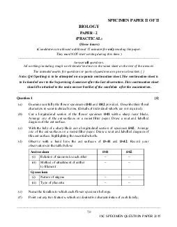
ity optimization are then used toinitialize a high-fidelity optimization, in which the path of each individual fiber tow istraced around the tank, and a detailed progressive failure finite element analysis isperformed. Helical Winding Multi-circuit FilamentWinding Process Hoop WindingFilament Winding PatternsFigure 1: Typical filament winding patterns.The Motor Case Design SoftwareIn a joint venture with the Alpha Star Corporation, M4 Engineering has recentlydeveloped a software package for optimizing the design of composite pressure vessels.The initial focus has been on solid rocket motor cases (hence the name of the software:Motor Case Design), but the software is equally applicable to pressure vesselapplications. The analysis and design process implemented in the Motor Case Design 4 •Assumes Geodesic(No Slip) Winding•Winding Angle isDetermined byGeometryAllows SimpleEstimates ofThickness and PlyA
4 ngle Winding Angle rr1?Figure 2: Geodes
ngle Winding Angle rr1?Figure 2: Geodesic winding patterns.Low Fidelity Analysis and OptimizationThe low-fidelity software described above has been implemented along with a simplegraphical user interface into a stand-alone software program suitable for performingsimplified design of composite rocket motor cases. All functionality of the low-fidelitysoftware is not available from the user interface, but enough is available to provide auseful tool for “quick-look” sizing efforts.High Fidelity Analysis and OptimizationWhile the optimization process described above is a very useful tool to determine theapproximate optimum design, many effects are neglected in the low-fidelity optimization.These include the effects of the detailed path the composite fibers take during thewinding process, the effects of tape tension and prestress, and the detailed failuremechanisms that are important for composite structu
5 res. In order to address these issuesan
res. In order to address these issuesand to ensure that the optimal design developed by the Motor Case Design software ismanufacturable and that it is really capable of withstanding the required loads, a second,higher-fidelity optimization step can be performed.In the high-fidelity optimization, the goal is to identify the minimum integer number ofhoop and helical plies required to withstand the required loads. Since a failure in thedome of a composite rocket motor case is much more dangerous than a hoop failure (inthe cylinder), an additional margin is built into the process to ensure that the failuremechanism will involve a hoop failure rather than a dome failure. In order to accomplishthis, the integer optimum is defined as the design that can withstand the required loads,but which will fail if hoop or helical plies are removed.The optimization process is initialized with the results from the low-fidelity
6 optimization,which gives a good initial
optimization,which gives a good initial guess of the total number of hoop and helical plies required. Ifthis initial design fails under the specified loads, the number of hoop and helical plies is 5 increased until the design can withstand the applied loads. Then the design is modified,with individual hoop and helical plies removed. The number of plies is adjusted until thedesign is found that can barely withstand the applied loads.This process is implemented through an automated scripting of the COBSTRAN andGENOA codes, and has been applied with excellent results. The high fidelity process isnot available in all versions of the Motor Case Design software, as both COBSTRAN andGENOA are required.Optimizing for a Specified Failure LocationOne interesting aspect of pressure vessel design is the impact that failure location has onthe safety of the overall design. While any failure of a high-pressure tank is p
7 otentiallycatastrophic, a dome failure (
otentiallycatastrophic, a dome failure (failure at the end) is potentially much more dangerous thana hoop failure (failure in the middle). This is primarily due to the fact that a dome failurehas the potential to turn the tank into a missile as the high-pressure gas escapes from thebreach.In order to address this issue, the MCD software has the capability to develop tailoreddesigns that fail primarily in the hoop region. This provides increased overall safety at aslight weight penalty.Designing a Motor CaseIn order to design a new motor case, simply select the “Design New Motor Case” optionfrom the main application’s File menu. This will invoke a wizard that leads the userthrough the process of setting up and executing the optimization problem. The first stepis to define the motor geometry, which is performed using the wizard screen shown inFigure 2. The Case Length is the distance from tang
8 ent line to tangent line, and the CaseRa
ent line to tangent line, and the CaseRadius is the radius of the cylindrical section of the case.The Minimum Pole Radius and Maximum Pole Radius represent the smallest and largestpermissible pole openings. A single pole radius cannot be specified because a geodesicwinding is assumed, which leads to a coupling between the winding angle and the poleradius. The minimum and maximum pole radius must be specified so that there is at leastone permissible winding with a pole radius in that interval. Recall that the units of lengthare arbitrary, and simply must be consistent with the units in the materials.dat file.Once the geometry is specified, the next page of the wizard (Figure 3) allows the user toenter the design stiffness requirements and load conditions the motor case. The softwaresupports minimum stiffness specifications for both bending and torsional stiffness, inconsistent units (inch-lb/radian, Newton-m
9 eter/radian, etc...). If there is no mi. If there is no mi")
eter/radian, etc...). If there is no minimumstiffness requirement, simply leave the default value of zero.The software supports internal pressurization as well as tension (compression), torsion,and bending loads. These are entered in a spreadsheet format, along with a load casedependent safety factor. It is assumed that tension, torsion, and bending loads are applieduniformly to the cylindrical section of the motor case, and that the domes are subject only 6 to pressurization loads. The software allows any number of load cases to be defined, andadditional rows are automatically added to the table as new load cases are added.Finally, the materials must be selected, using the wizard page shown in Figure 4. Thisincludes selecting the material to be used for hoop windings, selecting those to be usedfor helical windings, and selecting a nominal tape width. The final tape width will beslightly different from th
10 e nominal tape width to ensure uniform c
e nominal tape width to ensure uniform coverage of the helicalplies. Figure 3: Basic Geometry Input for Motor Case Design. 8 Low Fidelity OptimizationOnce the geometry, loads, and materials are defined, the optimization of the motor casebegins. This process contains two main parts. First, the software loops over the possiblewinding patterns that lead to uniform-coverage “star” patterns. For each winding pattern,the software determines the combination of helical winding angle, tape width, and polesize that gives a uniform coverage winding. Those winding patterns that have poleopening sizes in the allowable range are then identified, and the amount of compositematerial (total thickness of helical and hoop plies) required to withstand the applied loadsis determined. The lightest of these designs is then selected as the optimum. This ispresented to the user as an optimization log, which shows the w
11 inding patternsconsidered, and the optim
inding patternsconsidered, and the optimization results for those that have acceptable pole diameters. Afinal summary for the overall optimum result is then provided. The log supports normalwindows cut-and-paste functionality, so the results can be captured for reporting anddocumentation purposes. A typical optimization log is shown in Figure 5.Once the optimum design has been identified, a geometric model of the resulting motorcase is constructed and displayed in a 3-D viewing window (Figure 6). The inner andouter surfaces of the composite pressure vessel structure are shown, which allows therelative thickness distribution to be easily seen and verified. Figure 6: Low-fidelity Optimization Log Output. 10 ApplicationsThe MotorCaseDesign software has been applied to numerous example problems. Oneof the most instructive is the design of a solid rocket motor case based on an existingconfiguration. The desig
12 n length of the case (the cylindrical po
n length of the case (the cylindrical portion) is 120 inches, andthe design radius is 8 inches. The pole radii are constrained to be between 2 and 4 inches.The low-fidelity optimization was performed first, in which numerous winding schedules(particularly for the helical windings) were investigated, and the resulting pole radiicalculated. This is shown in tabular form in Figure 8. While a detailed discussion isbeyond the scope of this paper, the integer parameters defining the rows and columns ofthe table define the “star” pattern of the helical windings, and how many circuits arerequired before the pattern repeats itself.Figure 8 shows the pole radii calculated for each candidate winding. Since the poleradius was constrained to be between 2 inches and 4 inches, many of the windings areinfeasible. Those that satisfy the pole radius requirement are highlighted in yellow, andare selected for furthe
13 r analysis and ply thickness optimizatio
r analysis and ply thickness optimization based on laminate theory.The results of these analyses are shown in Figure 9. The optimal winding scheduleresults in a total composite weight of ~102 pounds, and a pole radius of ~2.77 inches.Now that the winding pattern is set, a high fidelity analysis/optimization is performed inCOBSTRAN/GENOA. The results of the final analysis are shown in Figure 10. Theinitial damage initiation occurs at approximately 7,600 psi of internal pressure, with finalfailure at around 7,640 psi. Example of Winding Optimization•Varied winding parameters (integers)•Optimized thickness for each winding possibility•Table Shows Pole Diameters•Yellow are “Feasible” Windings M-N2234567895.5162071.5961351.3547681.1755221.0427830.9431051.561290.849547 Figure 8: Winding Matrix Investigated in Low Fidelity Optimization. 11 HiFi Analysis ResultsDamage Progression to Fi