
Figure 1 The force applanation tonometry using the hardware adapter pictured above The clear acrylic cylinder is allowed to move freely within the black casing so that its mass provides a c ID: 954273
Download Pdf The PPT/PDF document "proposed system emulates fixed" is the property of its rightful owner. Permission is granted to download and print the materials on this web site for personal, non-commercial use only, and to display it on your personal computer provided you do not modify the materials and that you retain all copyright notices contained in the materials. By downloading content from our website, you accept the terms of this agreement.


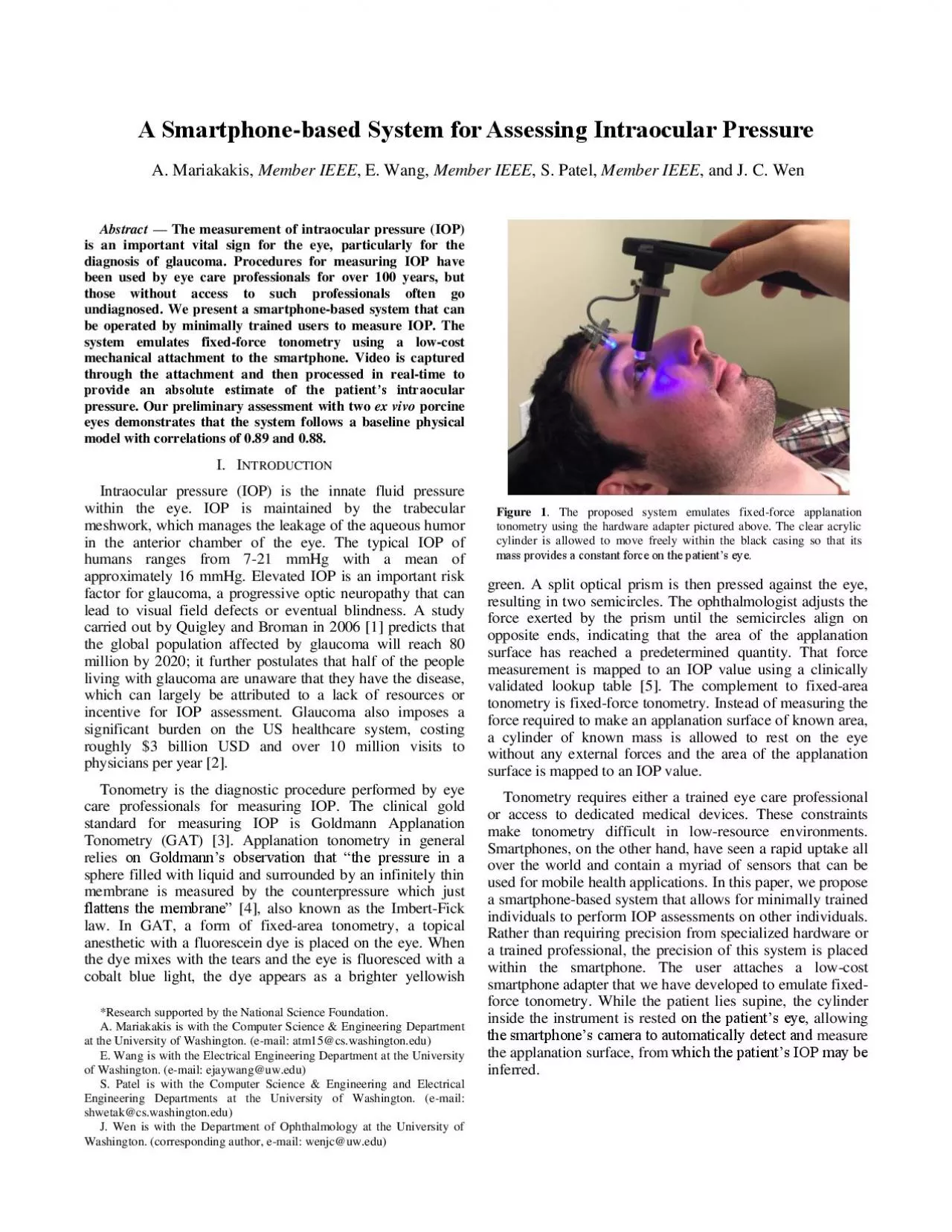
Figure 1 . The proposed system emulates fixed - force applanation tonometry using the hardware adapter pictured above. The clear acrylic cylinder is allowed to move freely within the black casing so that its mass provides a constant force on the patientâs eye. Abstract â The measurement of intraocular pressure (IOP) is an important vital sign for the eye, particularly for the diagnosis of glaucoma. Procedures for measuring IOP have been used by e ye care professionals for over 100 years, but those without access to such professionals often go undiagnosed. We present a smartphone - based system that can be operated by minimally tr ained users to measure IOP. The system emulates fixed - force tonometry using a low - cost mechanical attachment to th e smartphone. Video is captured through the attachment and then processed in real - time to provide an absolute estimate of the patientâs intrao cular pressure. Our preliminary assessment with two ex vivo porcine eyes demonstrates that the system follows a baseline physical model with correl ations of 0. 89 and 0. 88 . I. I NTRODUCTION Intraocular pressure ( IOP ) is the innate fluid pressure within the eye. IOP is maintained by the trabecular meshwork, which manages the leakage of the aqueous hum or in the anterior chamber of the eye. The typical IOP of humans ranges from 7 - 21 mmHg with a mean of approximately 16 mmHg . E levated IOP is an important risk factor for glaucoma, a progressive optic neuropathy that can lead to visual field defect s or eventual blindness . A study carried out by Quigley and Broman in 2006 [1] predicts that the global population affected by glaucoma will reach 80 million by 2020 ; i t further postulates that half of the people living with glaucoma are unaware that they have the disease, which can largely be attributed to a lack of resources or incentive for IOP assessment. Glaucoma a lso imposes a significant burden on the US healthcar e system, costing roughly $3 billion USD and over 10 million visits to physicians per year [2] . Tonometry is the diagnostic procedure performed by eye care p rofessionals for measuring IOP . The clinical gold standard for measuring IOP is Goldmann Applanation Tonometry (GAT) [3] . Applanation tonometry in general relies on Goldmannâs observation t hat âthe pressure in a sphere filled with liquid and surrounded by an infinitely thin membrane is measured by the counterpressure which just flattens the membraneâ [4] , also known as the Imbert - Fick law . In GAT, a form of fixed - area tonometry, a topical anesthetic with a fluorescein dye is placed on the eye. When the dye mixes with the tears and the eye is fluoresced with a cobalt blue light, the dye appears as a brighter yellowish *Research supported by the National Science Foundation. A. Mariakakis is with the Computer Science & Engineering D epartment at the University of Washington. (e - mail: atm15@cs.washington.edu) E. Wang is with the Electric al Engineering D epartment at the University of Washington. (e - mail: ejaywang@uw.edu ) S. Patel is with the Computer Sci ence & Engineering and Electrical Engineering Departments at the University of Washington. (e - mail: shwetak@cs.washington.edu) J. Wen is with the Department of Ophthalmology at the University of Washington. (corresponding author, e - mail: wenjc@uw.edu) green. A split optical prism is then pressed against the eye , resulting in two semicircles. The ophthalmologist adjusts the force exerted by the prism until the semicircles align on opposite ends , indicating that the area of the applanation surface has rea ched a predetermined quantity . That force measurement is mapped to a n IOP value using a clinically validated lookup table [5] . The complement to fixed - area tonometry is fixed - fo rce tonometry. Instead of measuring the force required to make an applanation surface of known area, a cylinder of known mass is allowed to rest on the eye without any external forces and the area of the applanation surface is mapped to an IOP value. Tonometry requires either a trained eye care professional or access to dedicated medical devices. These constraints make tonometry difficult in low - res ource environments. Smartphones, on the other hand, have seen a rap id uptake all over the world and conta in a myriad of sensors that can be used for mobile health applications . In this paper, we propose a smartphone - based system that allows for minimally trained individuals to perform IOP assessments on other individuals . Rather than requiring precision from specialized hardware or a trained professional, the precision of this system is placed within the smartphone. The user attaches a low - cost smartphone adapter that we have developed to emulate fixed - force tonometry . While the patient lies supine, the cylind er inside the instrument is rested on the patientâs eye, allowing the smartphoneâs camera to automatically detect and measure the applanation surface, from which the patientâs IOP may be inferred. A Smartph one - based System for Assessing Intraocular Pressure A. Mariakakis , Member IEEE , E. Wang , Member IEEE , S. Patel, Member IEEE , and J. C. Wen Figure 2 . The steps taken to estimate intraocular pressure from an RGB image of the applanation procedure. After converting the image into the HSV space, masks are defined for the clear acrylic cyli
nderâs base (outer ellipse) and the applanation surface (inner ellipse) using color an d intensity features as filters . Ellipses are detected on the insides of those masks and then mapped to absolute measurements given the 8 mm diameter of the acrylic cylinder. The diameter of the applanation surface is then mapped to the patientâs estimated IOP. II. A PPROACH A. Hardware The hardware adapter is shown in Figure 1 attached to an iPhone case. The most important part of the hardware is the clear ac rylic cylinder inside the black casing . The acrylic cylinder is allowed to move freely within the casing , but has notches to ensure that it does not fall out of the adapter. The acrylic cylinder has a diameter of 8 mm and a height of 63 mm . The 8 mm diameter was chosen such that it would capture a fairly large circle from a low eye pressure without being too difficult to use on patients with small palpebral fissures. The height of 63 mm was chosen for two reasons. (1) If the applanation surfa ce is placed too closely to the smartphoneâs camera, the resulting video becomes difficult to focus and the edges become blurry. ( 2 ) This combination of diameter, height, and material leads to a mass of 5.0 g , a mass for which the conversion from applanati on surface diameter to IOP has already been clinically validated for human eyes [5], [6] . Although conversion tables for larger masse s have been produced, studies have shown that the weight of the tonometer induces an increased pressure due to the di splacement of aqueous humor during applanation [6] . The black casing itself is designed such that the acrylic cylinder is optimally positioned in front of the smartphoneâs back - facing camera. Not only does this positioning include the alignment of the acrylic cylinder with the camera , but also the distance between the base of the acrylic cylinder and the camera. The black casing also blocks out ambient lighting to prevent any extraneous reflections from appearing in the acrylic cylinder. To enhance the visibility of the acrylic cylin der in the camera, the edge of the cylinderâs bottom surface is frosted. To emphasize the applanation surface in the camera, a n external LED is mounted on the casing ; in the future, the smartphoneâs flash could be redirected to the outside of the acrylic cylinder via a short fiber optic cable. W hen this lighting is reflected off of fluorescein dye, it shines as a bright yellowish green. B. Performing the Assessment Before receiving the assessment , the patient assumes a supine position . The user conducting the test administers a topical anesthetic with fluorescein dye (Fluorescein sodium 0.25%/Proparacaine 0.5%) to the patientâs eye . The user then hold s the smartphone over the patientâs eye such that only the weight of the acrylic cylinder is applied to it . This means that the smartphone should be as flat as possible ( i.e. , parallel to the ground) and the user should not apply any extra force on the smartphone ( i.e. , pressing down). The flatness of the smartphone is measured with the smartphoneâ s acceleromet er, operating as a sort of bubble level. The weight of the acrylic cylinder creates an elliptical applanation surface with a yellowish green outline when the LED is shone on the patientâs eye. The smartphoneâs camera records the applanation of the eye. The frames from the resulting video are then processed using computer vision to give a real - time estimate of the patientâs IOP. C . Video Analysis Figure 2 outlines the algorithm used to extract an IOP measurement from an RGB image . The overall goal of the algorithm is to detect two ellipses: the base of the clear acrylic cylinder (outer ellipse) and the applanation surface (inner ellipse) . Since the diamete r of the acrylic cylinder is known, the applanation surface can be assigned an absolute measurement by using the cylinder as a reference. Both of the ellipses should be relatively circular; however, the acrylic cylinder may appear slightly elliptical if th e hardware adapter is improperly mounted, and the applanation surface may be elliptical if the patient has significant astigmatism or corneal surface irregularities . As shown on the far left of Figure 2 , the edge of the acrylic cylinder appears bright and white, and the edge of the applanation surface appears as a dim mer yellow ish green . By filtering the image according to intensity and color information, binary masks can be produced to select the outlines of the circles. This information is most intuitively recovered from the image after it is converted into the HSV space. The mask for the inner ellipse bounds the hue between 15 - 45% , the saturation between 35 - 100% , and the value 15 - 100%. Together, these thresholds encode the greenish yellow Figure 3 . A variation of the Starburst technique by Li et al. [7] is used to estimate the innermost ellipse from a binary mask. After candidate points are selected from the inside, contiguous subsets of points are tested with least - squares elli pse fitting until the most circular is found. that appears due to the fluorescein . The mask for the outer ellipse is simpl er, thresholding the saturation between 0 - 20% and the value between 25 - 100 % . Both masks are smoothed using morphol ogical filtering operations to create contiguous contours . Each of the masks will have s
ome non - uniform thickness due to the application of the dye and extraneous reflections in the cylinder . The diameters of interest correspond to the innermost edges of these masks. S tandard circle detection methods would either discover many overlapping circles or none at all, depending on the evenness of the masks. Even worse, only part of the applanation surface may be visible if it overlaps with the sclera, which makes it more diff icult to see the fluorescein dye. For these reasons, we apply an adaptation of the pupil contour detection algorithm ( Figure 3 ) used by Li et al. in t heir Starburst work [7] . The ellipse detection starts by assuming the center of the ellipses given that the position of the clear acrylic in the cameraâs view is known. The algorithm then steps radially at 20 evenly spaced angles until an edge is reached in the mask ( illustrated with fewer angles for clarity ). This assumes that there are no contours that appear within the mask, which can happen for the applanation surface if the fluorescein pool s in the patientâs eye. Since extra blob s appear in the middle of the mask due to the distribution of the flu orescein, the radial steps start from a fixed distance just below the minimum expected radius to prevent them from stopping short. Most of the detected edge points should belong to the desired ellipse, but some may still belong to artifacts along the edge of the contour . The original S tarbu r st algorithm accounts for noisy ellipse points by fitting random subsets of points to ellipses and selecting the ellipse that minimizes the number of outliers . In the case of applanation, there is almost always a clean arc that appears in the image. Instead of random ized subsets of points, as used by Li et al. , the proposed system fits con tiguous subsets of points (three - quarters of the entire circumference) to ellipses . Although we noted earlier that the base of the acrylic cylinder and the applanation surface may appear elliptical, the ellipses should be relatively rounded. If the percent difference between an ellips e âs major and minor axes is greater than 10%, it is automatically rejected. Amongst the rest of the ellipses produced by the different subset s of edge points, the ellipse that best fits the data according to Euclidean distance is selected. The ellipses recovered from the two masks are then translated into circles with a radius equal to the average of the ellipsesâ axes . Given that the diameter of the clear acrylic cylinder is 8 mm, the absolute measurement of the applanation surface can be recovered by using the cylinder as a reference. Every time the user performs an app lanation, a time series of diame ter measurements is produced. The measurements of interest occur when the data is most stable since that is when the weight of the acrylic cylinder should be res ting on the eye ; t herefore, the system combines diameter measur ements by taking a mean over the measurements within a standard deviation of 0.25 mm over the course of 0.5 s . The final diameter measurement is mapped to an IOP value using a clinically validated look up table , such as the one published by Adolph Posner [5] . III. R ESULTS A. Data Collection Given the invasive nature of contact applanation tonometry , a feasibility evaluation has been performed on two freshly enucleated ex vivo porcine eyes bef ore deploying the system to living human patients . Although t here is not a clinically validated table that maps applanation surface diameter to IOP for animal eyes, the Imbert - Fick law still applies . The porcine eyes were inserted into a clay mold such that th e iris was horizontal to the ground, as if a patient w ere supine. The anterior chamber s of the eye s w ere cannulated and the IOP was artificially varied by the height of a saline - filled reservoir . A topical anesthetic with a fluorescein dye (Fluorescein sodiu m 0.25%/Proparacaine 0.5%) was applied to the eyes to assist in imaging the applanation surface. Tonometry measurements were obtained three times at every 5 mmHg between 1 5 and 40 mmHg , leading to a total of 32 measurements . Below 15 mmHg, the applana tion surfaceâs edge begins to overlap with the edge of the acrylic cylinder, making it difficult to s eparate the two . The upper bound exceeds the limits of diagnostic significance for elevated IOP. B . Comparison to the Imbert - Fick Law Although other methods of tonometry are available as a point of comparison for validation , they all have two drawbacks for our validation : (1) they require manual inspection ( e .g. , Schiøtz or Maklakov tonometers) and/or (2) they are calibrated specifically for in vivo human eyes ( e.g. , GATs) . Instead of a comparison to a possibly inaccurate ground truth, we validate our findings against what is expected from the Imbert - Fick law: � = � � = �� 1 4 � � 2 where � is the intraocular pressure, � is the mass applied to the eye, � is the acceleration due to gravity, and � is the diameter of the applanation surface. Although corrections Figure 4 . T he data recorded from the smartphone system and fit to the physical model e xpected from the Imbert - Fick law . The two curves lead to coeff icients of determinat
ion of 0. 89 and 0. 88 . have been proposed by ophthalmologists to account for properties like the coefficient of ocular rigidity and corneal curvature ( e.g. , [6] ), these models break down for ex vivo eyes. The measurements from each of the eyes were independently fit to the Imbert - Fick law using non - linear fitting. The mass parameter was used as the unknown parameter; if the data were to follow the Imbert - Fick law without deviation, the parameter resulting in the best fit would be 5g, the mass of the acrylic cylinder. Figure 4 shows the models that were fit to the two datasets. The clinical measurements validated by Adolph Posner [5] are also included as a point of reference. Even though Posn er only dealt with human eyes, the shape of the data should be similar to that of the ex vivo porcine eyes. When compared to the Imbert - Fick law, Posnerâs data shares a coefficient of determination ( � 2 ) 0.95 and the estimated mass according to the optimal fit is 5.01g , showing that it follows the model very closely . The fit for the first porcine eye leads to a coefficient of determination of 0. 8 9 and an estimated mass of 5. 04 g. The fit for the second eye does not obey the Imbert - Fick law as well; it result s in a lower coefficient of determination of 0. 88 and an estimated mass of 5 .94g. T he regressions overestimate low pressures and underestimates high pressures in all cases , a fact that has been observed by clinicians for other forms of tonometry as well [8] . The most promising observation is that there is a statistically significant separation between the diameters for 20 mmHg and 30 mmHg , the boundary that clinicians consider for the diagnosis of elevated IOP. IV. D ISCUSSION T he Imbert - Fick law assumes that the eyeâs membrane is perfectly elastic, flexible, and infinitely thin; prior work has shown that these assumptions do not hold for the cornea of the eye. For example, DF Woodhouse [6] notes that the volumetric displacement of aqueous humor induces an increase in the IOP, so he derives a correction term that takes into account the corneal curvature and rigidity. We plan to apply Woodhouseâs model once evaluations are performed on cadaveric and in v ivo human eyes. It is very important that the entire weight of the acrylic cylinder is the only force applied to the eye during applanation. The smartphoneâs accelerometer is used to ensure that the cylinderâs weight is applied perpendicular to the eye, as suming that the user is supine. However, it is possible that the user can add an additional force by pushing down on the cylinder. When this happens, the cy linder slides into the black casing past a specific depth. This could be solved using a contact sens or, but would require an active sensing mechanism Instead, the next iteration of the hardware design has holes along the edge of the casing at the threshold depth. When the acrylic cylinder is pushed past the holes, additional light is shone into it. This can be detected through the smartphoneâs camera without additional sensing hardware, making it a more desirable design. Another planned refinement in the next hardware iteration is the use of a macro lens , which is used in photography when a camera must f ocus on a small subject at close range . The primary reason that the acrylic cylinder used for applanation is 63 mm tall is to ensure that the applanation surface remains in focus during the assessment. With a macro lens, the applanation surface can be much closer to the smartphone camera. Assuming a constant diameter, r educing the height of the acrylic cylinder would decrease its mass, but the cylinder could be made with a denser acrylic or metal rings could be attac hed to the base to add weight . A CKNOWLEDGMENT We thank Chen Xin for the supply of porcine eyeballs for our evaluation. We also thank Neil E. Warren for the hardware adapter for our system. R EFERENCES [1] H. A. Q uigley and A. T. Broman, âThe number of people with glaucoma worldwide in 2010 and 2020,â Br. J. Ophthalmol. , vol. 90, no. 3, pp. 262 â 267, 2006. [2] D. B. Rein, P. Zhang, K. E. Wirth, P. P. Lee, T. J. Hoerger, N. McCall, R. Klein, J. M. Tielsch, S. Vijan, and J. Saaddine, âThe economic burden of major adult visual disorders in the United States,â Arch. opthalmology , vol. 124, no. 12, pp. 1754 â 1760, 2006. [3] S. Stevens, C. Gilbert, and N. A. Astbury, âHow to measure intraocular pressure: applanation tonomet ry,â Community Eye Heal. , vol. 20, no. 64, p. 74, 2007. [4] H. Goldmann, âApplanation tonometry,â in Transactions of the Second Glaucoma Conference , 1957, pp. 167 â 219. [5] A. Posner, âModified conversion tables for the Maklakov tonometer,â Eye. Ear. Nose Throat Mon. , vol. 41, pp. 638 â 644, 1962. [6] D. F. Woodhouse, âFive g ME applanation tonometry Pt to P0 conversion nomogram and table,â Exp. Eye Res. , vol. 15, no. 4, pp. 509 â 512, Apr. 1973. [7] D. Li, D. Winfield, and D. J. Parkhurst, âStarburst: A hybrid algorithm for video - based eye tracking combining feature - based and model - based approaches,â in 2005 IEEE Computer Society Conference on Computer Vision and Pattern Recognition (CVPRâ05) - Workshops , 2005, vol. 3, pp. 79 â 79. [8] A. Posner, âThe tonomat app lanation tonometer: a comparison with the Goldmann applanation tonometer and the applanometer,â Eye. Ear. Nose Throat Mon. , vol. 48, no. 3, p. 189, 19