
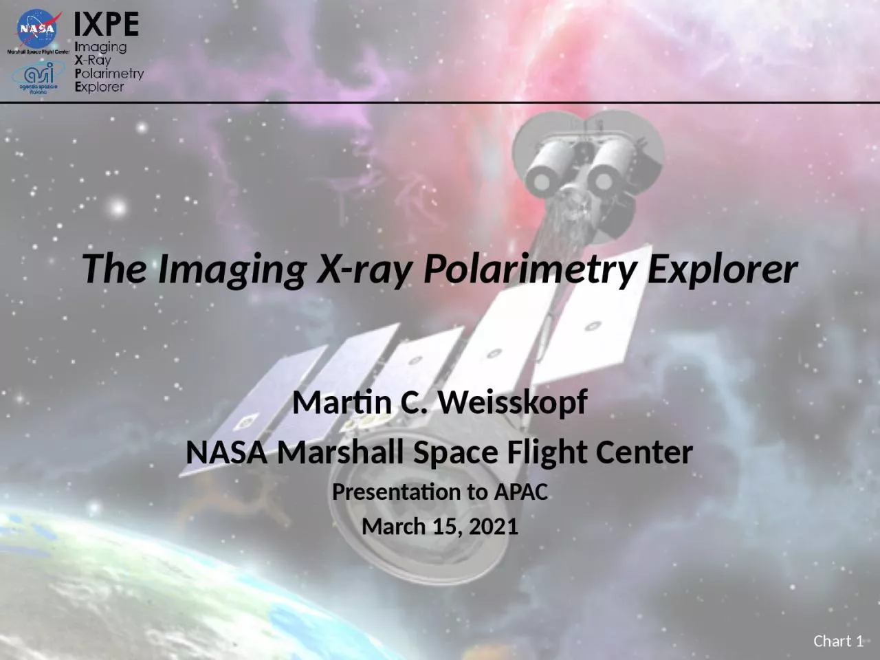
Martin C Weisskopf NASA Marshall Space Flight Center Presentation to APAC March 15 2021 52 m total length 40 m focal length Forward Star Tracker Detector Unit 1 of 3 Mirror Module Assembly ID: 1021401
Download Presentation The PPT/PDF document "The Imaging X-ray Polarimetry Explorer" is the property of its rightful owner. Permission is granted to download and print the materials on this web site for personal, non-commercial use only, and to display it on your personal computer provided you do not modify the materials and that you retain all copyright notices contained in the materials. By downloading content from our website, you accept the terms of this agreement.


1. The Imaging X-ray Polarimetry ExplorerMartin C. WeisskopfNASA Marshall Space Flight CenterPresentation to APACMarch 15, 2021
2. 5.2 m total length4.0 m focal lengthForward Star TrackerDetector Unit(1 of 3)Mirror Module Assembly(1 of 3)IXPE Deployed
3. IXPE Exists!Janice Houston, IXPE Lead Systems Engineer in residence at Ball, with stowed observatory
4. The IXPE TeamSAT currently comprises > 90 scientists from 12 countriesNagoya University Thermal Shields
5. The Science TeamInvestigatorsL. Baldini (Co-IPI), W. Baumgartner, R. Bellazzini, S. Bongiorno, E. Costa, J. Kolodziejczak, L. Latronico, H. Marshall, G. Matt, F. Muleri, S. O’Dell, B. Ramsey (DPI), R. Romani, P. Soffitta (IPI), A. Tennant, M. Weisskopf (PI) Collaborators (75 from 12 countries)I. Aguido, L.A. Antonelli, M. Bachetti, S. Bianchi, R. Bonino, A. Brez, N. Bucciantini, F. Capitanio, E. Cavazzuti, E. Churazov, S. Ciprini, M. Cocchi, L. Costamante, A. De Rosa, E. Del Monte, N. Di Lalla, I. Donnarumma, V. Doroshenko, M. Dovčiak, S. Ehlert, T. Enoto, Y. Evangelista, S. Fabiani, J. Garcia, S. Gunji, K. Hayashida, J. Heyl, A. Ingram, W. Iwakiri, S. Jorstad, V. Karas, V. Kaspi, F. Kislat, T. Kitaguchi, H. Krawczynski, M. Kuss, I. Liodakis, G. Madejski, S. Maldera, A. Manfreda, F. Marin, A. Marinucci, A. Marscher, F. Massaro, I. Mitsuishi, T. Mizuno, S. Ng, N. Omodei, C. Oppedisano, L. Pacciani, A. Papitto, G. Pavlov, M. Perri, M. Pesce-Rollins, P.-O. PetruccI, M. Pilia, A. Possenti, J. Poutanen, S. Puccetti, M. Razzano, C. Sgrò, P. Slane, G. Spandre, L. Stella, R. Sunyaev, T. Tamagawa, F. Tavecchio, R. Taverna, Y. Tawara, N. Thomas, A. Trois, R. Turolla, J. Vink, K. Wu, S. Zane
6. The Working GroupsScience Working Group (SWG)G. Matt (IT) & S. O’Dell (US), Co-ChairsScience Advisory Team (SAT)G. Matt (IT) & R. Romani (US), Co-ChairsSAT Topical Working Groups (TWG), LeadsPulsar Wind Nebula & Radio Pulsars, N. Bucciantini (IT)Supernova remnants, P. Slane (US)Accreting stellar-mass black holes, M. Dovčiak (CZ)Accreting neutron stars, J. Poutanen (FI)Magnetars, R. Turolla (IT)Radio-quiet AGN and Sgr A*, F. Marin (FR)Blazars & radio galaxies, A. Marscher (US)Calibration Working GroupW. Baumgartner (US), F. Muleri (IT), & J. Kolodziejczak (US)Science Analysis & Simulation Working GroupL. Baldini (IT) & H. Marshall (US)
7. Shield and Collimator Suppress BackgroundX-rayShieldX-ray ShieldDetector UnitOn-axis TargetMirror Module AssemblyOff-axis BackgroundCollimator
8. Mirror-Shell Production Process(+)(+)(-)8. Separate shell from mandrel in chilled water4. Polish mandrel to 0.3-0.4 nm RMS7. Electroform Nickel/Cobalt shell onto mandrel6. Passivate mandrel surface to reduce shell adhesion3. Diamond turn mandrel to sub-micron figure accuracy1. Machine mandrel from aluminum bar5. Conduct metrology on the mandrel2. Coat mandrel with electroless nickel (Ni-P)Ni/Co electroformed IXPE mirror shellMirror-shell formingMandrel fabrication
9. The OpticsParameterValueNumber of mirror modules3Number of shells per mirror module24Focal length4 mTotal shell length600 mmRange of shell diameters162–272 mmRange of shell thicknesses0.16–0.25 mmShell materialElectroformed nickel–cobalt alloyEffective area per mirror module 166 cm2 (@ 2.3 keV); > 175 cm2 (3–6 keV)Angular resolution (HPD)≤ 27 arcsecField of view (detector limited)12.9 arcmin squareFront Spider AssemblyOuter Housing TubeRear Spider AssemblyX-ray Mirror ShellsCentral Support TubeMMA, showing 24 shellsMMA with Thermal Shield on endThree IXPE Mirror Module Assemblies
10. X-ray calibration of the optics occurred at MSFC’s 100-m X-ray test facilityStray Light Test FacilityMirror Module AssemblyX-Y stage with detector mounting plate
11. Angular ResolutionMMA#1#2#36.4 keV18.9″24.8″24.2″4.5 keV18.9″25.0″26.9″2.3 keV18.7″24.5″26.7″Values in the table are half-power diameters (HPDs) for the individual MMAs alone. After adjustment for alignment errors, detector resolution, focus, etc., the on-orbit system-level resolution is 28″.At-focus images for MMA1, MMA2 and MMA3 (left to right) taken at 2.3 keV, 4.5 keV and 6.4 keV (top to bottom).
12. Imaging polarimetryIXPE 30″ half-power diameter on Chandra image of the Crab Nebula
13. The detection principle is based upon the photoelectric effectDetection Principle, where
14. The DetectorGas Pixel DetectorElectronicsX Rays InCollimatorThe initial direction of the K-shell photoelectron is determined by the orientation of the incident photon’s electric vectorThe distribution of the photoelectron initial directions measures the degree of polarization and the position angle
15. Detector Properties ParameterValueSensitive area15 mm × 15 mm (13 x 13 arcmin) Fill gas and asymptotic pressureDME @ 0.656 atmosphereDetector window50-µm thick berylliumAbsorption and drift region depth10 mmGEM (gas electron multiplier)copper-plated 50-µm liquid-crystal polymerGEM hole pitch50 µm triangular latticeNumber ASIC readout pixels300 × 352ASIC pixelated anodeHexagonal @ 50-µm pitchSpatial resolution (FWHM)≤ 123 µm (6.4 arcsec) @ 2 keVEnergy resolution (FWHM)0.57 keV @ 2 keV (∝ √E)Useful energy range 2 - 8 keV
16. The Detectors The Detectors mounted to the spacecraft top deck at Ball Aerospace
17. Filter Calibration Wheel AssemblyFilter and Calibration Wheel (FCW), providing open, attenuated, and closed positions, plus four 55Fe-powered calibration sources: Cal A – Bragg-reflected polarized 2.98-keV (Ag-L𝛼 fluorescence) and 5.89-keV (Mn-K𝛼)Cal B – unpolarized 5.89-keV spot Cal C – unpolarized 5.89-keV floodCal D – unpolarized 1.74-keV (Si-K𝛼 fluorescence) flood
18. Minimum Detectable Polarization (MDP)RS is the observed source counting rateRB is the observed background counting ratet is the integration time M is the modulation factor—i.e., the amplitude of the variation of the ensemble of position angles for a 100%-polarized source
19. Neural-Network AnalysisBaseline moments analysis is a simple, effective, long-studied and well-understood method of extracting information from ionization tracks made by the photo-electron in the detector gas Machine Learning (neural-network) techniques can extract more information from each trackImproves position-angle (PA) measurements, especially at higher energiesAllows one to compute statistical and reconstruction errors for each eventMildly improves estimates of the energy and conversion point of each event
20. First Year’s Mission — Release 1Next version will be released 6 months prior to launchObserving plan is from input from the IXPE Science Advisory TeamSeven Topical Working Groups (TWG), based upon category of sourceNeeded exposure times assume moments-method event reconstructionWill increase somewhat, based upon results from recent calibrationHowever, neural-network event reconstruction will enhance the sensitivityImproves MDP99 by ~15% (relative) for fixed exposure timeReduces exposure time by ~30% for fixed MDP99Source Category# SourcesTime (Ms)Pulsar Wind Nebulae32.6Supernova Remnants33.0Accreting Neutron Stars81.8Accreting Black Holes20.6Magnetars22.0Radio Quiet AGN and Sgr A*42.8Blazars and Radio Galaxies113.2ToOs63Total3919
21. Radio Pulsars Radio Pulsars Perform X-ray phase-resolved polarimetry to test models for a radio pulsar’s X-ray emissionCrab Pulsar — grey is optical, blue is IXPE Emission geometry and processes are still unsettled.Competing models predict differing polarization behavior with pulse phase.X-rays provide a clean probe of geometry.Absorption likely more prevalent in visible band.Radiation process entirely different in radio band.Recently discovered no pulse phase-dependent variation in polarization degree and position angle @ 1.4 GHz.140-ks observation of the Crab pulsar gives ample statistics to track polarization degree and position angle.
22. MicroquasarsMicroquasars Perform X-ray spectral polarimetry on microquasars to use the position angle to help localize the emission site (accretion disk, corona, jet) and determine the spinFor a microquasar in an accretion-dominated state, scattering polarizes the disk emission.Polarization rotation versus energy is greatest for emission from inner disk.Inner disk is hotter, producing higher energy X-rays.Disk orientation from other experiments may be used to constrain GRX1915+105 model.a = 0.50±0.04; 0.900±0.008; 0.99800±0.00003 (200-ks observation)
23. Active Galaxies: Cen AActive galaxies powered by supermassive black holes with jets Radio polarization implies the magnetic field is aligned with jetDifferent electron-acceleration models predict different dependences in X-rays RegionMDP99Core1.4%Knots C+F+G 21%ULXs25%, 15%ULX sourcesJet knots
24. Test QEDStudy magnetars (pulsing neutron stars with magnetic fields up to 1015 Gauss)Non-linear QED predicts magnetized-vacuum birefringenceRefractive indices of the two polarization modes differ from 1 and from each otherImpacts polarization and position angle as functions of pulse phase, but not the fluxExample is 1RXS J170849.0-400910, with an 11-s pulse periodCan exclude QED-off at better than 99.9% confidence in 250-ks observation
25. ConclusionWe are keenly looking forward to opening this new window on the sky by adding image resolved polarimetry to the arsenal of tools to study the X-ray emission from astrophysical sources. Scheduled launch date is 2021 November 17!