
Turn on the carrier gas flow using Table I to determine an appropriate head pressure Note A small amount of particles may exit the column when the carrier gas is first turned on This is normal as ID: 8701
Download Pdf The PPT/PDF document " Turn on the carrier gas flow using Tabl..." is the property of its rightful owner. Permission is granted to download and print the materials on this web site for personal, non-commercial use only, and to display it on your personal computer provided you do not modify the materials and that you retain all copyright notices contained in the materials. By downloading content from our website, you accept the terms of this agreement.


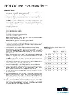
PLOT Column Instruction Sheet Table I: Approximate head pressures (at 40 °C) using hydrogen and helium. Head Pressure for Q-, QS-, S-, and Head Pressure for Msieve 5A and all Alumina BOND Column Length Internal Diameter Approx. psi Approx. kPa Approx. psi Approx. kPa 15 m 0.25 mm 6.5 45 10 69 15 m 0.32 mm 3 21 6.5 45 15 m 0.53 mm 1.5 10 2 14 30 m 0.25 mm 9.5 66 11.5 79 30 m 0.32 mm 6 41 9 30 m 0.53 mm 2.5 17 3.5 24 50 m 0.25 mm 18 124 — — 50 m 0.32 mm 10 69 14 97 50 m 0.53 mm 3.5 24 6 41 Installation Instructions 1.Before removing the previously installed column from the gas chromatograph (GC), be sure to turn off the detector and cool all heated temperature zones. 2.Once all zones of the GC are cooled, turn off all gases. Remove the installed column, plug each end with silicone septa (or column end caps), and return the column to its original box. 3.Remove the new PLOT column from its box. Remove the septa (or column end-caps) that are on each end of the PLOT column. If your column is tied onto the metal cage with high-temperature string, do not remove the string. This high-temperature string can withstand temperatures up to 400 °C. 4.Attach the appropriate GC capillary nut (fitting) onto the inlet side of the column. Attach the appropriate GC column ferrule onto the inlet side of the column. See our nut and ferrule com - patibility guide for Agilent GCs. Fused silica columns: 0.25 mm columns, use 0.4 mm ID ferrule 0.32 mm columns, use 0.5 mm ID ferrule 0.53 mm columns, use 0.8 mm ID ferrule MXT columns: 0.25 mm and 0.32 mm columns, use 0.5 mm ID ferrule 0.53 mm columns, use 0.8 mm ID ferrule Note: Do not install the capillary column nut (fitting) or ferrule onto the outlet side of the column at this time; this will be performed later. Note: See Helpful Hints section for information on using particle traps. 5. 20 cm from both ends. Make sure that a clean, square cut is obtained. Install the inlet side of the column into the GC injection port at the appropriate distance (see your GC manual to determine the correct installation distance). Turn on the carrier gas flow, using Table I to determine an appropriate head pressure. Note: A small amount of particles may exit the column when the carrier gas is first turned on. This is normal as particles can become dislodged when the column is cut, when a ferrule is tightened onto a column, or due to vibrations during transport. See section C for tips on pro - tection from particles. 7.Purge the column with clean, dry carrier gas for at least 20 minutes. During this purging step, check for leaks at the injector connections using an electronic leak detector. Note that the use of carrier gas traps is also highly recommended. Important: If using hydrogen as the carrier gas, be sure to safely vent the gas exiting the col - umn and the split vent. 8.Set the injection port temperature according to the method, but do not exceed the maximum Program the GC oven to heat up at 5 °C/min up to the column's maximum temperature. Once the column’s maximum temperature is reached, hold this temperature for at least 60 minutes for porous polymer columns (Q-, QS-, S- and U-BOND), and for at least 2 hours for molecular sieve and alumina columns. Do not exceed 6 hours for any column. Cool the GC oven. Do not turn off the carrier gas. Do not remove the inlet side of the column from the injection port. Attach the appropriate capillary column nut (fitting) to the outlet side of the column. Attach the appropriate GC column ferrule to the outlet side of column. Trim an additional 1 cm from the outlet side of the column and verify that a clean, square cut is obtained. Before installing the column into the detector, pre-seat the ferrule onto the column using a capillary installation gauge. This will help prevent dislodged particles from entering the detector. Install the column into the detector at the appropriate distance (see your GC manual to deter - mine the correct installation distance). Confirm that your detector gases and electronics are turned on, then set the appropriate detector and injector temperatures for your analysis and allow them to stabilize. You are now ready to use the column. © 2019 Restek Corporation. All rights reserved. Printed in the U.S.A. www.restek.com #600-55-001 Rev. date: 06/19 Restek patents and trademarks are the property of Restek Corporation. (See www.restek.com/Patents-Trademarks for full list.) Other trademarks in Restek literature or on its website are the property of their respective owners. Restek registered trademarks are registered in the U.S. and may also be registered in other countries. Questions about this or any other Restek product? Contact us or your local Restek representative (www.restek.com/contact-us). Helpful Hints Temperature Limits Never exceed the recommended maximum temperature of the column, which is given on the box label and product web page for each PLOT column. B.Column Regeneration Occasionally, alumina PLOT columns need to be regenerated to remove moisture. To regener - ate, set the carrier gas head pressure as shown in Table I, set the GC oven temperature to the maximum column operating temperature, and condition the column for 6 hours. Occasionally, molecular sieve PLOT columns also need to be regenerated to remove moisture. To regenerate, set the carrier gas head pressure as shown in Table I, set the GC oven temperature to the maximum column temperature, and condition the column for 1–3 hours. Caution: If using hydrogen as a carrier gas, subjecting molecular sieve columns to high tem - peratures using hydrogen carrier gas for more than an hour will cause surface activity, result - ing in carbon monoxide (CO) peak tailing. Protection from Particles PLOT columns are not ideal for use in MS or valve systems due to their potential to generate particles that can contaminate and, in severe cases, damage GC parts. If a PLOT column must be used in these instances, a particle trap is necessary to reduce the chances of particles get - ting into the GC system. For fused silica columns, see Table II for a list of available particle traps. For MXT columns, contact Customer Service to order custom particle traps and install them using the appropriate MXT connector (cat.# 21385 for 0.32 mm ID columns and cat.# 21384 for 0.53 mm ID columns). If the PLOT column will be connected to a mass spectrometer (MS), the pressure drop (vacu - um) may dislodge particles into the MS. To minimize the amount of particles from entering the MS, couple the detector end of the PLOT column to a particle trap (e.g., 5 m x 0.25 mm ID fused silica tubing coated with 0.25-0.50 m of a nonpolar stationary phase, such as Rtx-1 phase). Use a connector suitable for MS application. If the PLOT column will be connected to a non-MS detector, connecting a particle trap to the detector end of the column is recommended. To ensure protection against particles flushing back into a valve/flow switching setup, con - necting a particle trap to the injector end of the PLOT column is recommended. If the PLOT column is connected using a valve/flow switching setup, use of a particle trap on the outlet and inlet ends is recommended to minimize the number of particles entering the GC system. Conditioning the column as instructed under steps 6-11 (previous page) using three times higher gas flow to elute any loose particles is recommended. After column condi - tioning is complete, restore normal column flow and connect to the detector as described in steps 12-13. Now your column is stable for valve/flow switching applications. D.To prevent high boiling point compounds from contaminating a PLOT column, use of a precol - umn (backflush column) or a valve/flow switching system should be considered. E.Please note that PLOT columns have a unique appearance due to the particle deposition on the inside wall of the columns. Variation in color and appearance is normal and does not affect performance. F.Never abruptly pull the inlet end of the column from the injector while under pressure; this can cause a pressure surge in the column, resulting in particles being dislodged. Instead, turn off pressure to the injector and allow it to drop to atmospheric pressure before disconnecting the column. Fused Silica PLOT Column Particle Trap Description Includes qty. cat.# PLOT Column Particle Trap, 0.25 mm ID Press-Tight connectors (2); 2.5 m, 0.25 mm ID column; high-temperature string ea. 19774 PLOT Column Particle Trap, 0.32 mm ID Press-Tight connectors (2); 2.5 m, 0.32 mm ID column; high-temperature string ea. 19753 PLOT Column Particle Trap, 0.53 mm ID Press-Tight connectors (2); 2.5 m, 0.53 mm ID column; high-temperature string ea. 19754 Table II: Fused Silica PLOT Column Particle Traps For particle traps for MXT columns, contact Customer Service.