/
Analysis Program Analysis Program

Analysis Program - PDF document

singh
singh . @singh
Follow
344 views
Uploaded On 2021-06-29

Analysis Program - PPT Presentation

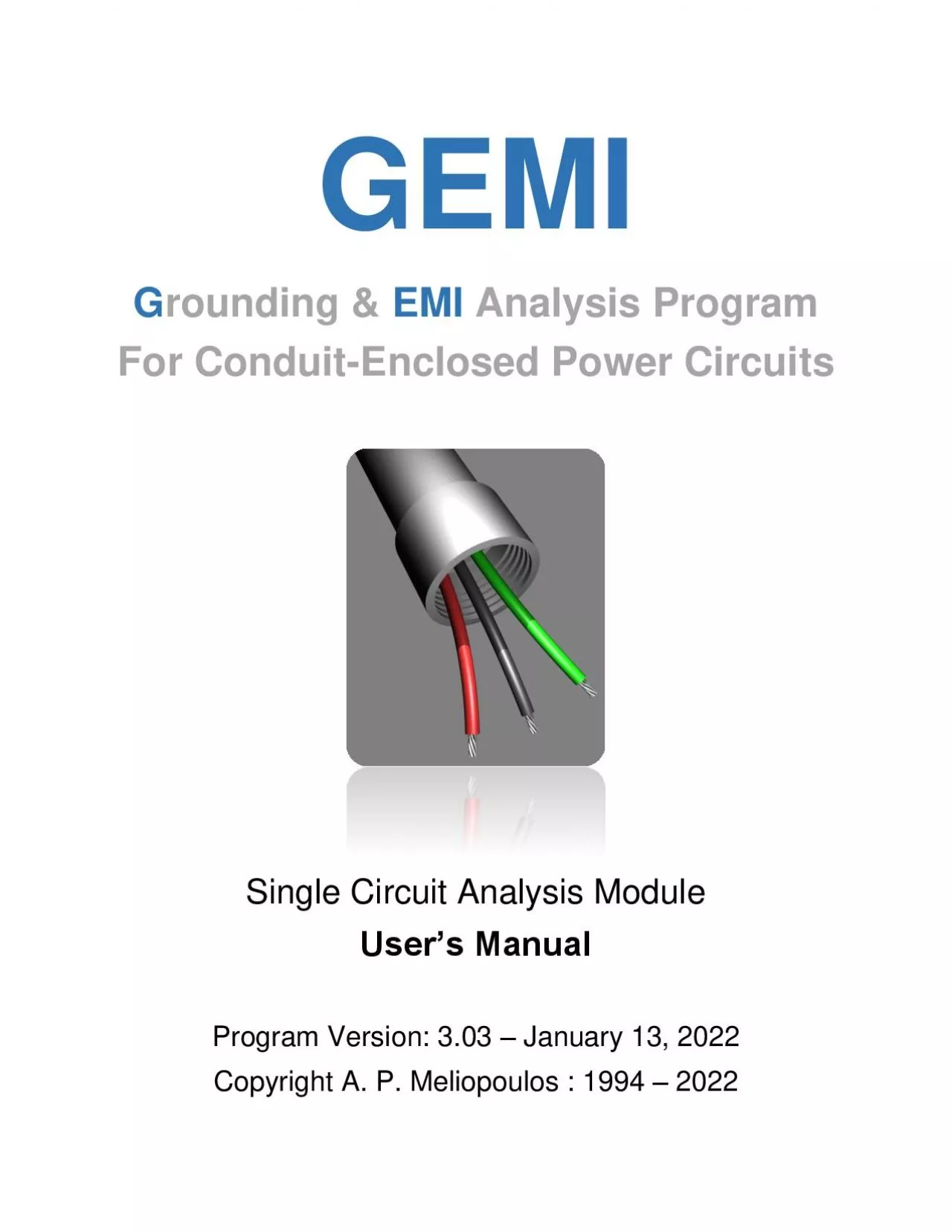
GEMI G rounding EMI For Conduit Enclosed Power Circuits Single Circuit Analysis Module Users Manua Program Version 3 0 2 August 16 2020 Copyright A P Meliopoulos 20 20 2 Tab ID: 849073

current conduit phase impedance conduit current impedance phase voltage conductor figure table temperature gemi data size function 2in length

Share:

Link:

Embed:

Download Presentation from below link

Download Pdf The PPT/PDF document "Analysis Program" is the property of its rightful owner. Permission is granted to download and print the materials on this web site for personal, non-commercial use only, and to display it on your personal computer provided you do not modify the materials and that you retain all copyright notices contained in the materials. By downloading content from our website, you accept the terms of this agreement.


Presentation Transcript

1 GEMI G rounding & EMI Analysis Prog
GEMI G rounding & EMI Analysis Program For Conduit - Enclosed Power Circuits Single Circuit Analysis Module User’s Manua Program Version: 3 .0 2 – August 16 , 2020 Copyright A. P. Meliopoulos – 20 20 2 Table of C ontents 1. GEMI Historical Review ................................ ................................ ............................... 3 2. The GEMI User Interface ................................ ................................ ............................ 7 3. Allowable Conduit Length ................................ ................................ .......................... 10 4. Allowable Length versus Arc Voltage ..........................

2 ...... ................................
...... ................................ ........ 11 5. Impedance versus Current ................................ ................................ ........................ 12 6. Magnetic Field and Per meability ................................ ................................ ............... 13 7. Steel Conduit with Supplemental Ground Conductor ................................ ................ 14 8. Allowable Circuit Length without Conduit ................................ ................................ .. 15 9. Fault Current at Source Power ................................ ................................ .................. 16 Appendix A: Steel Conduit Parameters .........................

3 ....... ................................
....... ................................ ......... 17 Appendix B: Alum inum Conduit Data ................................ ................................ ............ 34 Appendix C: PVC Conduit Data ................................ ................................ .................... 35 Appendix D: High Current Test Results ................................ ................................ ......... 36 3 1. G EMI Historical Review The GEMI ( G rounding and E lectro - M agnetic I nfluence) program facilitates the design of steel conduit enclosed power circuits. The first three releases of this program (1994 - 1998) were compatible with the IBM PC with the DOS operating system.

4 In 1999, the first Windows version w
In 1999, the first Windows version was released (see Table 1. 1) followed by two other releases in 2002 and 2004 . A major software update was undertaken in 2018, which resulted in the present version (GEMI 3.00) released in 2020. Table 1 .1 : GEMI Release History Year Released Version OS 1994 SCA.1 DOS 1996 GEMI.1 1998 GEMI 2.4 1999 GEMI W 1.0 Windows 2002 GEMI W 2. 0 2004 GEMI W 2. 2 2020 GEMI W 3.0 GEMI is based on a mathematical model known as Finite Element Analysis . This method t akes into account the electromagnetic fields developing in and around conduit - enclosed circuits and evaluates the effectiveness of steel conduits in limiting EMI and

5 providing a low impedance e arth curre
providing a low impedance e arth current return to fault currents. The original GEMI model was developed in the late 1980s. The original model was validated by extensive laboratory and field test s performed in the eary 1990’s (See Figure 1. 1). 4 Figure 1. 1: Field Tests for the Validation of the Original GEMI Model During the period 2018 - 202 0 a new version of the GEMI model was developed, providing several enhancements over the original model including :  Modeling of non - concentric arrangement effects  Use of English or metric units .  Automatic default settings based on NEC article 250.  Conduit fi ll factor computation  Detailed circ

6 uit cross - section view with EM fiel
uit cross - section view with EM field displays .  Visualization of EM fields along any user selectable path .  Increased accuracy and computational efficiency. The new model was validated by conducting new field and laboratory testing (See Figures 1. 2 and 1. 3). The tests performed in December 2019 and additional tests in 2019. The detailed test report and verification can be obtained from STI. A summary of the results id given in Appendix D. The new user interface developed f or GEMI version 3.00 is described in the next section . 5 (a) (b) Figure 1. 2 : High Current Field Test Setup – December 2018 (a) Test Setup Block Diagram (b) Test S

7 etup View 6 (a) (b) Figu
etup View 6 (a) (b) Figure 1. 3 : Permeability Measurement Setup - 2019 (a) Test Setup Block Diagram (b) Test Setup View 7 2. The GEMI User Interface The GEMI main window is illustrated in Figure 2.1. It provides seven functions, which illustrate the performance of a single steel conduit enclosed power circuit: 1. Allowable Conduit Length 2. All owable Length versus Arc Voltage 3. Impedance versus Current 4. Magnetic Field and Permeability 5. Conduit with Suppl. Ground Conductor 6. Allowable Circuit Length w/o Conduit 7. Faut Current at "Source Poer” The GEMI function is selected by clicking on the radio butto ns located under the Sele

8 ct Function title (See Figure 2.1)
ct Function title (See Figure 2.1) Figure 2.1 : Function Selection Radio Buttons 8 The input data required for each function are entered in the blocks titled:  Phase Conductor Parameters  Ground Conductor Parameters  Conduit Parameter s, and  System Parameters The phase and ground conductor parameters include:  Conductor type and size (selected from tables)  Conductor x and y coordinates  Temperature  Insulation thickness Coordinates, temperature and thickness are entered in English or metri c units. Units are seected by radio buttons ocated under the “Units” tite – See Figure 2.1). When the conductor coordinates or the insu

9 lation thickness is modified, the cross
lation thickness is modified, the cross - section view drawing is automatically updated. The conductor positions can also be edited by moving the conductor images in the cross - section view using the mouse. Note that conductors must not be overlapping. Furthermore, all conductors must be located inside the conduit . The circuit section view can be zoomed and panned using the mouse wheel and the right mouse button respectively. Conductor selection is made using the left mouse button. A left button double click on a conductor opens the conductor selection library window. The Reset Zoom button re - centers the image to the default position. The Plot button opens a field plot window, which displa

10 ys the computed magnetic field along
ys the computed magnetic field along a user specified path (See Figure 2.2). The path is indicated by a red line ( or cir cle) appearing on the circuit cross - section display . The path can be modified using the mouse. A number of radio buttons located on the field plot window allow the selection of the plotted quantity, namely:  Magnetic scalar potential (A)  Magnetic flux density (B)  Magnetic field intensity (H)  Current density (J)  Relat ive permeability ( μ ) Additional radio buttons select the plot path shape (straight line or circular), the plotted field component direction (parallel or perpendicular to the path) , plot - scaling mode (automatic or fixed), an

11 d the plot interpolation mode (li near o
d the plot interpolation mode (li near or none). The seven GEMI computational functions are described in Sections 3 through 9. 9 Figure 2.2 : Field Plot Window Example 10 3 . Allowable Conduit Length The Allowable Conduit Length function computes the maximum length of a steel conduit enclos ed circuit that will ensure fault current is higher than a specified level. The required input d ata for this function are :  Phase Conductor Type, Size and Temperature  Conduit Type, Size and Temperature  Operating Voltage  Arc Voltage  Fault Current Figure 3.1 : Allowable Conduit Length Function 11 4. Allowable Length versus Arc Voltage The Allow

12 able Length versus Arc Voltage function
able Length versus Arc Voltage function generates plots of the permissible circuit length as a function of arc voltage for three electric current levels Input Data:  Phase Conductor Type, Size and Temperature  Conduit Type, Size and Temperature  Operating Voltage  Current Range of Interest Figure 4.1 : Allowable Length versus Arc Voltage Function 12 5 . Impedance versus Current The Impedance versus Current function generates tables of plots of the circuit impedance as a function of electric current. Input Data:  Phase Conductor Type, Size and Temperature  Conduit Type, Size and Temperature  Current Range of Interest Figure

13 5.1 : Impedance versus Current Functi o
5.1 : Impedance versus Current Functi on 13 6 . Magnetic Field and Permeability The Magnetic Field and Permeability function generates plots of the magnetic field intensity, magnetic flux density and relative permeability along a line starting at the phase conductor center and ending at the con duit external surface. Input Data:  Phase Conductor Type, Size and Temperature  Conduit Type, Size and Temperature  Electric Current Figure 6.1 : Magnetic Field and Permeability Function 14 7 . Steel Conduit with Supplemental Ground Conductor The Condu it with Supplemental Ground Conductor function computes the maximum length of a steel conduit enclosed circuit equi

14 pped with a supplemental ground conducto
pped with a supplemental ground conductor that will ensure fault current is higher than a specified leve l Input Data:  Phase Conductor Type, S ize and Temperature  Conduit Type, Size and Temperature  Ground Conductor Type, Size and Temperature  Operating Voltage  Arc Voltage  Fault Current Figure 7.1: Steel Conduit with Supplemental Ground Conductor Function 15 8 . Allowable Circuit Length without Cond uit The Allowable Circuit Length without Conduit function computes the maximum length of a circuit consisting of a phase and a ground conductor, which will ensure that the fault current is higher than a specified level. Input Data: Phase Conductor Type, S ize

15 and Temperature  Ground Conductor
and Temperature  Ground Conductor Type, Size and Temperature  Operating Voltage  Arc Voltage  Fault Current Figure 8 .1: Allowable Circuit Length without Conduit Function 16 9 . Fault Current at Source Power The Faut Current at “Source Poer” function co utes the fault current of a steel conduit enclosed circuit of a user specified length , assuming the source has infinite capacity and there is a fault at the end of the circuit with user defined fault parameters (arc voltage). Input Data:  Phase Conductor Ty pe, Size and Temperature  Conduit Type, Size and Temperature  Circuit Length  Operating Voltage  Arc Voltage F

16 igure 8 .1: Fault Current at Source Pow
igure 8 .1: Fault Current at Source Power Function 17 Appendix A: Steel Conduit Parameters The conduit types and sizes included in the GEMI program l ibrary are listed in Tables A1 through A4 . Furthermore, the steel permeability parameters for EMT, IMC, and GRC type steel conduits are listed. The measurement methodology used to obtain the permeability data is briefly described. Table A1: EMT Steel Co nduit Data # Size Inner Diameter (inches) Outer Diameter (inches) Resistance (Ohms/mile) 1 1/2IN(16) 0.622 0.706 3.95360 2 3/4IN(21) 0.824 0.922 2.57750 3 1INCH(27) 1.049 1.163 1.74890 4 1 - 1/4IN(35) 1.380 1.510 1.17390 5 1 - 1/2IN(41) 1.610

17 1.740 1.012 70 6 2INCH(53) 2.0
1.740 1.012 70 6 2INCH(53) 2.067 2.197 0.79560 7 2 - 1/2IN(63) 2.731 2.875 0.54630 8 3INCH(78) 3.356 3.500 0.44670 9 3 - 1/2IN(91) 3.834 4.000 0.33910 10 4INCH(103) 4.334 4.500 0.30070 18 Table A2: GRC Steel Conduit Data # Size Inner Diameter (inches) Outer Diameter (inches) Resistance (Ohms/mile) 1 1/2IN(16) 0.632 0.840 1.69990 2 3/4IN(21) 0.836 1.050 1.28960 3 1INCH(27) 1.063 1.315 0.86850 4 1 - 1/4IN(35) 1.394 1.660 0.64070 5 1 - 1/2IN(41) 1.624 1.900 0.53510 6 2INCH(53) 2.083 2.375 0.39980 7 2 - 1/2IN(63) 2.489 2.875 0.25140 8 3INCH(78) 3.090 3.500 0.19260 9

18 3 - 1/2IN(91) 3.570 4.000 0.15990
3 - 1/2IN(91) 3.570 4.000 0.15990 10 4INCH(103) 4.050 4.500 0.13530 11 5INCH(129) 5.073 5.563 0.09990 12 6INCH(155) 6.093 6.625 0.07690 19 Table A3: IMC Steel Conduit Data # Size Inner Diameter (inches) O uter Diameter (inches) Resistance (Ohms/mile) 1 1/2IN(16) 0.660 0.815 2.10190 2 3/4IN(21) 0.864 1.029 1.53850 3 1INCH(27) 1.105 1.290 1.08460 4 1 - 1/4IN(35) 1.448 1.637 0.81980 5 1 - 1/2IN(41) 1.683 1.882 0.67400 6 2INCH(53) 2.149 2.359 0.50750 7 2 - 1/2 IN(63) 2.557 2.857 0.29590 8 3INCH(78) 3.176 3.476 0.24080 9 3 - 1/2IN(91) 3.671 3.971 0.20960 10 4INCH(103) 4.166

19 4.466 0.18560 20 Table A
4.466 0.18560 20 Table A3: Stainless Steel Conduit Data # Size Inner Diameter (inches) Outer Diameter (inches) Resistance (Ohms/mile) 1 3/ 8IN 0.493 0.675 14.46474 2 1/2IN 0.622 0.840 9.64763 3 3/4IN 0.824 1.050 7.26017 4 1IN 0.828 1.060 4.88985 5 1 - 1/4IN 1.380 1.660 3.61238 6 1 - 1/2IN 1.610 1.900 3.02078 7 2IN 2.067 2.375 2.24748 8 2 - 1/2IN 2.469 2.875 1.41720 9 3IN 3.090 3.500 1.08370 10 4IN 4.026 4.500 0.76085 11 5IN 5.073 5.563 0.59000 12 6IN 6.093 6.625 0.45400 21 Permeability Measurement The permeability measurement for IMC, EMT and GRC materials was pe

20 rformed using samples of IMC, EMT and G
rformed using samples of IMC, EMT and GRC conduits listed in Table A - 4. Two windings were added on each sample, specifically, a primary winding distributed along the complete circumference, and a concentrated secondary winding. Figure A - 1 illustrates the sample dimensions and the added windings. The primary winding was driven by a sinusoidal voltage source. The primary RMS winding current and the secondary RMS winding voltage were measured at various amplitudes, and the permeability parameters were derived from these measurements. Table A - 4 : Conduit Sample Dimensions # Material Size Outside Diameter ( d - inches) Width ( w - inches) Height ( h - inches) Weight (g)

21 Turns Prim/Sec 1 EMT 2” 2.20â
Turns Prim/Sec 1 EMT 2” 2.20” 0.068” 2.25” 123 g 84/20 2 IMC 2” 2.36” 0.111” 1.83” 174 g 88/20 3 GRC 2” 2.38” 0.145” 2.03” 255 g 90/20 4 Stainless Steel 1” 1 .33” 0.138” 1.347” 110 g 44 Figure A - 1: Conduit Sample s The RMS V - I measurement data for IMC, EMT and GRC materials are listed in Tables R - 3, R - 4 nad R - 5 respectively. Note that the Tables include: 22  Primary winding current (column 2)  Seconda ry winding voltage (column 3)  Phase angle between voltage and current (column 4)  Computed magnetic field intensity H (column 5)  Computed magnetic fl

22 ux density B (column 6)  Computed
ux density B (column 6)  Computed relative permeability (column 7) Note that t he measurement of the V /I p h as e angle ma k e s possible the separation of the hysteresis effect from the magnetic saturation effect. The magnetic field intensity H is computed from the measured RMS current using the formula: where a and d are defined in the F igure below, N 1 is the number of primary turns and θ is the phase angle between voltage and current. Note that the factor sin( θ ) in the above equation removes the hysteresis effect from the permeability saturation model . Figure A - 2 : Conduit Sample Geo metric Data The magnetic flux density B is computed from the measu

23 red RMS voltage using the formula:
red RMS voltage using the formula: 23 where a and d are defined in the above Figure, N 2 is the number of secondary turns and ω is the excitation frequency. Note a lso that: Assuming sinusoidal conditions, and converting to the frequency domain: Or: The above formula can be used to compute the material permeability before saturation on set. Subsequently, multiple measurements were taken by increasing the excitation current to levels that ensured magnetic material saturation. The collected data were analyzed using a time domain model. The saturation curves were derived by minimizing th e RMS error between measurement and model results. The saturation curves were expresse

24 d in terms of piece - wise linear/quadra
d in terms of piece - wise linear/quadratic functions as illustrated in Figure A - 3. Figures A - 4 , through A - 15 provide plots of the measurement data for IMC , EMT and GRC ma terials . 24 \ Figure A - 3 : B versus H function definition 25 Table A - 5 : RMS Measurement Data for IMC Material File # Current (Arms) Voltage (Vrms) Phase (Degrees) H At/m B Tesla μ re 0 0.0000 0.0000 66.0000 0.00 0.00 N/A 1 0.2620 0.0358 49.6800 97.96 0.04 294.59 2 0.3660 0.0588 44.4000 125.58 0.06 376.96 3 0.5110 0.1020 38.1400 154.76 0.10 530.69 4 0.7520 0.1960 31.0200 190.04 0.20 830.44 5 0.8560 0.230

25 0 30.1500 210.84 0.23 878.37 6
0 30.1500 210.84 0.23 878.37 6 1.0610 0.2910 29.2000 253.84 0.29 923.08 7 1.2390 0.3370 28.9500 294.11 0.34 922.64 8 1.5570 0.4090 29.0500 370.76 0.41 888.26 9 1.7820 0.4540 29.2000 426.33 0.46 857.46 10 2.0810 0.5090 29.4400 501.59 0.52 817.09 11 2.2400 0.5370 29.4900 5 40.75 0.54 799.61 12 2.6300 0.6010 29.8400 641.75 0.61 754.08 13 2.8140 0.6300 29.9700 689.36 0.64 735.87 14 3.0920 0.6720 30.1500 761.58 0.68 710.49 15 3.5150 0.7340 30.4100 872.53 0.74 677.36 16 3.9600 0.7910 30.6700 990.58 0.80 642.97 17 4.4610 0. 8540 31.0500 1128.36 0.86 609.42 1

26 8 4.9110 0.9110 31.6700 1264.43
8 4.9110 0.9110 31.6700 1264.43 0.92 580.13 18a 5.5380 1.0000 34.3700 1533.163 1.012 525.189 19 6.0180 1.0400 36.5000 1755.43 1.05 477.04 19a 6.5640 1.0920 39.4900 2047.07 1.10 429.53 20 7.0690 1.1190 41.5100 2297.49 1.13 392.18 21 8.2680 1.1790 46.2800 2930.34 1.19 323.97 22 9.1250 1.2160 48.8900 3371.56 1.23 290.41 23 10.2700 1.2600 51.0000 3913.97 1.27 259.21 24 12.0900 1.3060 52.9300 4730.63 1.32 222.29 26 Table A - 6 : RMS Measurement Data for EMT Material File # Current (Arms) Voltage (Vrms) Phase (Degrees) H At/m B Tesla μ re 0 0.136 0.014 66.40 5

27 8.61 0.02 211.74 0a 0.229 0.03
8.61 0.02 211.74 0a 0.229 0.030 58.73 92.05 0.03 291.38 0b 0.292 0.045 54.15 111.30 0.05 355.74 0c 0.400 0.077 46.63 136.74 0.09 501.18 1 0.506 0.122 40.18 153. 53 0.14 706.89 1a 0.748 0.220 34.50 199.24 0.25 982.26 2 1.012 0.329 32.45 255.35 0.37 1146.11 3 1.542 0.496 33.01 395.05 0.55 1116.88 4 2.029 0.619 35.83 558.55 0.69 985.83 5 2.527 0.716 40.97 779.16 0.80 817.45 6 3.040 0.779 46.19 1031.66 0.87 671. 70 8 3.512 0.813 49.66 1258.85 0.91 574.50 9 4.082 0.849 52.57 1524.36 0.95 495.44 10 4.465 0.871 54.55 1710.48 0.97 452.97 11 4.950

28 0.895 56.47 1940.45 1.00 410.2
0.895 56.47 1940.45 1.00 410.29 12 5.464 0.919 58.00 2179.08 1.03 375.16 13 5.953 0.938 59.23 2405.39 1.05 346.89 14 7.212 0.991 61.57 2982.52 1.11 295.57 15 8.251 1.032 63.04 3458.47 1.15 265.44 16 9.002 1.061 63.98 3804.23 1.19 248.10 17 10.260 1.106 65.30 4383.47 1.24 224.45 27 Table A - 7 : RMS Measurement Data for GRC Material File # Current (Arms) Voltage (Vrms ) Phase (Degrees) H At/m B Tesla μ re 0 0.0000 0.0000 55.0000 0.00 0.00 1 0.2640 0.0419 45.0900 94.35 0.03 246.96 2 0.3580 0.0626 41.5200 119.75 0.04 290.76 3 0.5100 0.1040

29 36.2600 152.22 0.07 380.04 4 0
36.2600 152.22 0.07 380.04 4 0.7470 0.1860 30.1800 189.50 0.13 545.95 5 1.0270 0.2850 26.7200 233.02 0.20 6 80.30 6 1.2270 0.3490 25.7200 268.71 0.24 722.44 7 1.5050 0.4280 25.1400 322.65 0.30 737.86 8 1.7190 0.4820 25.0900 367.84 0.34 728.87 9 2.0590 0.5590 25.2600 443.38 0.39 701.28 10 2.5560 0.6570 25.7200 559.75 0.46 652.87 11 3.0320 0.7400 26.1500 674 .32 0.52 610.41 12 3.4910 0.8140 26.5200 786.60 0.57 575.61 13 3.9850 0.8880 26.9000 909.83 0.62 542.89 14 4.6180 0.9760 27.3400 1070.28 0.68 507.24 15 5.0000 1.0260 27.5400 1166.63 0.72 489.19 16 5

30 .9420 1.1410 27.9900 1407.26 0.8
.9420 1.1410 27.9900 1407.26 0.80 450.99 17 7.1460 1 .2730 28.5100 1721.23 0.89 411.38 18 8.1630 1.3700 30.0000 2059.65 0.96 369.99 19 10.260 1.575 33.38 2848.61 1.10 307.54 20 12.280 1.706 40.27 4005.59 1.19 236.90 28 Figure A - 4 : RMS Votage vs Current for IMC 2” Sae Figure A - 5 : V - I Phase Angle vs Current for IMC 2” Sae 29 Figure A - 6 : B vs H for IMC 2” Sae Figure A - 7 : PWLQ model of B vs H for IMC Material 30 . Figure A - 8 : RMS Votage vs Current for EMT 2” Sae Figure A - 9 : V - I Phase Ange vs Current for EMT 2” Sae 31

31 Figure A - 10 : B vs H for EMT
Figure A - 10 : B vs H for EMT 2” Sae Figure A - 1 1 : PWLQ model of B vs H for EMT Material 32 Figure A - 1 2 : RMS Votage vs Current for GRC 2” Sae Figure A - 1 3 : V - I Phase Ange vs Current for GRC 2” Sae 33 Figure A - 1 4 : B vs H for GRC 2” Sae Figure A - 1 5 : PWLQ model of B vs H for GRC Material 34 Appendix B: Aluminum Conduit Data The parameters of the aluminum conduit sizes included in the GEMI program library are listed in Table B1. Table B1: Aluminum Conduit Data # Size Inner Diameter (inches) Outer Dia meter (inches) Resistance (Ohms/mile) 1 1/2INCH(16) 0.622

32 0.840 0.4010 2 3/4INCH(21) 0.824
0.840 0.4010 2 3/4INCH(21) 0.824 1.050 0.3018 3 1INCH(27) 1.049 1.315 0.2033 4 1 - 1/4IN(35) 1.380 1.660 0.1502 5 1 - 1/2IN(41) 1.610 1.900 0.1256 6 2INCH(53) 2.067 2.375 0.0934 7 2 - 1/2IN(63) 2.4 69 2.875 0.0589 8 3INCH(78) 3.068 3.500 0.0450 9 3 - 1/2IN(91) 3.548 4.000 0.0375 10 4INCH(103) 4.026 4.500 0.0316 11 5INCH(128) 5.047 5.563 0.0233 12 6INCH(155) 6.065 6.625 0.0180 35 Appendix C: PVC Conduit Data The parameters of the PVC conduit size s included in the GEMI program library are listed in Table C1. Table C1: PVC Conduit Data # Size Inner Diameter (inches) Outer Diameter (inc

33 hes) 1 1/2INCH(16) 0.622 0.840
hes) 1 1/2INCH(16) 0.622 0.840 2 3/4INCH(21) 0.824 1.050 3 1INCH(27) 1.049 1.315 4 1 - 1/4IN(35) 1.380 1.660 5 1 - 1/2IN(41) 1.610 1.900 6 2INCH(53) 2.067 2.375 7 2 - 1/2IN(63) 2.469 2.875 8 3INCH(78) 3.068 3.500 9 3 - 1/2IN(91) 3.548 4.000 10 4INCH(103) 4.026 4.500 11 5INCH(128) 5.047 5.563 12 6INCH(155) 6.065 6.625 36 Appendix D: High Current Test Results This Appendix summarizes the results of the high current conduit impedance measurements. Table D - 1: 3” EMT Conduit Tests – 500 kcm Phase & Neutral Conductor # Configuration Current (A) Voltage (V) Impedance Magnitude ( m Ω ) I

34 mpedance Phase (Degrees) Temperatur
mpedance Phase (Degrees) Temperatur e ( 0 C) 1 P - N, C - G 345 3.159 9.159 52.2 20.17 2 1336 14.36 10.74 56.5 20.30 3 1981 25.71 12.98 60.37 20.58 4 P - N - C - G 1429 12.87 8.999 51.79 22.94 5 2300 25.27 10.99 55.59 24.19 6 P - C - G 1404 20.83 14.84 43.13 30.34 7 1763 26.24 14.89 43.36 30.74 Table D - 2: 3” GRC Conduit Tests – 500 kcm Phase & Neutral Conductor # Configuration Voltage (V) Current (A) Impedance Magnitude ( m Ω ) Impedance Phase (Degrees) Temperature ( 0 C) 1 P - N, C - G 3.461 385.7 8.974 52.90 20.43 2 14.36 1413 10.16 56.54 20.43 3 25.81 2050 1

35 2.59 61.30 20.45 4 P - N - C - G
2.59 61.30 20.45 4 P - N - C - G 12.10 1420 8.515 56.91 20.58 5 25.26 2299 10.98 61.08 20.72 6 P - C - G 4.734 354.3 13.36 41 .48 21.93 7 20.79 1395 14.89 45.49 22.08 8 26.33 1734 15.18 44.98 22.47 9 P - N - C (NG) 3.086 355.0 8.695 53.15 24.23 10 14.27 1428 9.985 56.10 24.33 11 25.39 2161 11.75 58.20 24.43 12 P - C (NG,FN) 12.89 350.3 36.78 29.43 24.99 37 13 27.65 1041.8 26.5 5 32.02 25.42 14 21.14 701.3 30.15 31.15 26.35 38 Table D - 3: 3” IMC Conduit Tests – 500 kcm Phase & Neutral Conductor # Configuration Voltage (V) Current (A) Impedance M

36 agnitude ( m Ω ) Impedance Phase (
agnitude ( m Ω ) Impedance Phase (Degrees) Temperature ( 0 C) 1 P - N, C - G 3.308 368.1 8.987 55.17 20.96 2 14.93 1448 10.31 55.59 24.18 3 25.40 2029 12.51 60.48 24.26 4 P - N - C - G 11.39 1387 8.209 56.44 23.13 5 24.88 2302 10.81 61.07 23.47 6 P - C - G 4.629 361.2 12.81 46 .70 20.97 7 20.60 1357 15.17 47.39 21.29 8 26.16 1720 15.20 47.08 21.77 9 P - N - C (NG) 2.955 357.6 8.266 51.57 25.04 10 13.54 1394 9.707 55.33 24.52 11 25.10 2160 11.62 58.02 24.66 12 P - C (NG,FN) 12.76 361.9 35.25 34.73 26.26 13 20.76 691.7 30.01 35.09 29.62 14 27.54 1053

37 .9 26.13 35.93 27.79 39
.9 26.13 35.93 27.79 39 Table D - 4: 3” STAINLESS Conduit Tests – 500 kcm Phase & Neutral Conductor # Configuration Voltage (V) Current (A) Impedance Magnitude ( m Ω ) Impedance Phase (Degrees) Temperature ( 0 C) 1 P - N, C - G 2.668 351 7.599 49.02 21.29 2 11.68 1431 8.154 46.46 27.79 3 24.24 2489 9.738 52.29 28.05 4 P - N - C - G 9.793 1389 7.046 48.31 26.68 5 22.02 2574 8.552 53.68 27.00 6 P - C - G 4.028 344.9 11.68 35.0 7 21.31 7 17.34 1460 11.87 32.87 21.74 8 25.54 2009 12.71 29.43 24.56 9 P - N - C (NG) 2.513 339.4 7.406 43.67 29.09 10 10.90 1416

38 7.696 44.95 29.11 11 23.98 259
7.696 44.95 29.11 11 23.98 2597 9.233 50.12 29.26 12 P - C (NG,FN) 9.574 397 24.12 7.478 29.74 13 27.43 1238 22.15 8.36 3 30.08 40 Comparison with Model The WinIGS simulated conduit self - impedance for 100 ft conduit is 16.55 m Ω . Adding the estimated coupling impedance ( at 0.56 m Ω per coupling x 9 couplings ) yields: Z model = 16.55 + 9 x 0.56 m Ω = 21.59 m Ω The above is consistent with the measured value range of 22 – 24 m Ω . WinIGS/GEMI Simulation Result 41 Table D - 5: 2” EMT Conduit Tests – 3/0 Copper Phase & Neutral Conductor # Configuration Voltage (V) Current (A) Impedance Magnitude ( m Ω

39 ) Impedance Phase (Degrees) Tempe
) Impedance Phase (Degrees) Temperature ( 0 C) 1 P - N, C - G 3.223 201.5 16.00 30.5 20.85 2 14.52 793.6 18.30 39.56 20.91 3 26.71 1219.4 2 1.91 38.03 30.94 4 P - N - C - G 12.61 806.2 15.63 37.47 22.29 5 26.35 1423.0 18.52 42.30 27.86 6 P - C - G 6.571 205.6 31.96 23.72 22.95 7 23.42 789.6 29.67 27.68 25.90 8 27.52 968.4 28.42 26.92 25.44 9 P - N - C (NG) 3.231 207.1 15.61 28.72 41.13 10 14.27 1 428.9 9.984 56.09 24.33 11 26.48 1374.7 19.27 38.27 32.92 12 P - C (NG,FN) 12.48 212.4 58.76 29.95 41.71 13 28.06 696.2 40.29 29.93 41.66 14 28.00 681.7

40 41.08 27.37 38.43 42 Table D
41.08 27.37 38.43 42 Table D - 6: 2” GRC Conduit Tests – 3/0 Copper Phase & Neutral Conductor # Con figuration Voltage (V) Current (A) Impedance Magnitude ( m Ω ) Impedance Phase (Degrees) Temperature ( 0 C) 1 P - N, C - G 3.288 204.9 16.05 31.26 20.33 2 14.00 800.8 17.48 36.94 20.35 3 26.65 1306.8 20.39 39.56 25.05 4 P - N - C - G 12.14 788.6 15.39 35.68 20.55 5 26.35 1477.4 17.84 42.61 24.39 6 P - C - G 6.643 201.3 33.01 20.13 21.12 7 23.98 766.1 31.30 24.09 21.48 8 27.64 893.0 30.95 24.05 23.33 9 P - N - C (NG) 3.157 205.0 15.40 30.93 31.69 10 13.78 798.6 1

41 7.26 36.03 31.54 11 26.55 1431
7.26 36.03 31.54 11 26.55 1431.3 18.55 38.59 26.26 12 P - C (NG,FN) 12.47 214.8 58.07 26.07 32.02 13 28.11 674.0 41.70 27.59 30.41 14 28.25 690.1 40.94 24.77 27.12 43 Table D - 7: 2” IMC Conduit Tests – 3/0 Copper Phase & Neutral Conductor # Configuration Voltage (V) Current (A) Impedance Magnitude ( m Ω ) Impedance Phase (Degrees) Temperature ( 0 C) 1 P - N, C - G 3.116 198.0 15.73 29.66 21.24 2 14.55 796.3 18.28 39.95 21.24 3 26.43 1273.3 20.76 39.95 27.79 4 P - N - C - G 12.23 795.9 15.37 36.43 21.64 5 26.11 1458.5 17.90 41.65 27.11 6 P - C - G 6.580 195.

42 7 33 .63 24.66 22.39 7 25.68
7 33 .63 24.66 22.39 7 25.68 780.02 32.92 25.07 23.49 8 27.34 917.7 29.79 27.66 27.11 9 P - N - C (NG) 3.108 202.9 15.32 28.87 36.74 10 13.93 797.6 17.47 36.70 36.23 11 26.27 1358.3 19.34 37.15 29.07 12 P - C (NG,FN) 11.65 201.3 57.90 32.40 35.85 13 27.92 655.2 42.61 29.92 36.16 14 27.78 650.3 42.72 26.32 32.76 44 Table D - 8: 1” EMT Conduit Tests – #4 Copper Phase & Neutral Conductor # Configuration Voltage (V) Current (A) Impedance Magnitude ( m Ω ) Impedance Phase (Degrees) Temperature ( 0 C) 1 P - N, C - G 2.291 42.74 53.62 9.839 21.16 2 9.420 172.4 54

43 .63 9.958 21.13 3 24.87 374.8
.63 9.958 21.13 3 24.87 374.8 66.35 9.879 21.52 4 P - N - C - G 7.630 155.2 49.16 10.16 29.78 5 27.12 466.4 58.15 9.479 33.84 6 P - C - G 18.32 229.4 79.8 7 12.73 46.21 7 28.49 337.6 84.39 12.85 47.91 8 28.37 390.07 72.60 13.40 37.68 9 P - N - C (NG) 3.846 82.83 46.45 11.95 22.84 10 11.50 233.2 49.34 11.74 22.92 11 23.79 453.2 52.51 12.92 23.37 12 P - C (NG,FN) 9.859 82.27 120.0 24.55 27.05 13 22.45 23 7.6 94.50 23.08 28.61 14 28.69 311.4 92.13 21.10 33.49 45 Table D - 9: 1” GRC Conduit Tests – #4 Copper Phase & Neutral Conductor # Configuration

44 Voltage (V) Current (A) Impedanc
Voltage (V) Current (A) Impedance Magnitude ( m Ω ) Impedance Phase (Degrees) Temperature ( 0 C) 1 P - N, C - G 4.626 83.89 55.14 9.426 20.25 2 13.35 235.3 56.74 10.32 20.27 3 27.91 411.5 67.83 10.84 30.76 4 P - N - C - G 10.74 237.7 45.19 11.02 20.62 5 24.50 453.7 54.01 11.77 27.19 6 P - C - G 5.737 83.81 68.4 5 12.03 21.69 7 16.32 237.0 68.88 12.52 21.75 8 28.08 385.8 72.78 13.51 23.18 9 P - N - C (NG) 4.608 87.26 52.81 10.44 35.53 10 13.09 240.1 54.53 10.62 35.07 11 26.72 464.1 57.58 12.60 34.18 12 P - C (NG,FN) 11.08 82.54 134.0 20.99 36.58 13 24.46

45 236 .7 103.0 21.04 36.36 14
236 .7 103.0 21.04 36.36 14 28.45 293.5 96.92 20.80 35.63 46 Table D - 10: 1” IMC Conduit Tests – #4 Copper Phase & Neutral Conductor # Configuration Voltage (V) Current (A) Impedance Magnitude ( m Ω ) Impedance Phase (Degrees) Temperature ( 0 C) 1 P - N, C - G 4.785 86.51 55.31 9.665 20.82 2 13.40 233.9 57.29 10.37 21.07 3 27.69 416.6 66.47 11.07 34.19 4 P - N - C - G 10.30 232.1 44.37 11.38 21.73 5 24.48 473.4 51.72 12.50 31.31 6 P - C - G 4.962 80.67 61.5 1 14.53 22.40 7 16.40 234.9 69.82 13.16 22.66 8 28.33 357.8 79.16 12.94 26.32 9 P - N - C (NG) 3.8

46 23 78.39 48.78 11.54 35.51 10
23 78.39 48.78 11.54 35.51 10 12.65 239.3 52.88 11.59 34.94 11 26.79 485.7 55.15 13.38 35.80 12 P - C (NG,FN) 9.723 80.61 121.0 22.80 36.63 13 24.77 240 .7 103.0 21.04 36.02 14 28.44 291.3 97.63 21.23 36.63 47 Table D - 11: 1” Stainess Stee Conduit Tests – #4 Copper Phase & Neutral Conductor # Configuration Voltage (V) Current (A) Impedance Magnitude ( m Ω ) Impedance Phase (Degrees) Temperature ( 0 C) 1 P - N, C - G 4.549 82.47 55.16 7.543 21.31 2 13.45 237.6 56.61 7.670 21.32 3 28.06 428.9 65.42 7.627 27.07 4 P - N - C - G 11.00 239.9 45.87 7.354 21.77

47 5 23.87 473.4 50.43 7.561 25
5 23.87 473.4 50.43 7.561 25.17 6 P - C - G 6.367 84.03 75.7 7 5.090 22.13 7 16.88 234.0 75.12 4.860 22.33 8 28.23 385.3 73.26 4.683 23.65 9 P - N - C (NG) 4.711 85.59 55.04 6.499 32.48 10 12.79 233.9 54.69 6.432 32.14 11 26.62 465.7 57.16 6.867 29.82 12 P - C (NG,FN) 11.53 79.27 146.0 1.715 32.75 13 19.59 150 .2 130.0 1.982 32.78 14 28.65 232.2 123.0 2.116 31.49 48 Comparison with Model The WinIGS simulated conduit self - impedance for 100 ft. conduit is 16.55 m Ω . Adding the estimated coupling impedance ( at 0.56 m Ω per coupling x 9 couplings ) yields: Z model = 102.1 + 9 x

48 1.26 m Ω = 113.45 m Ω The abov
1.26 m Ω = 113.45 m Ω The above is near the measured value range of 123 – 146 m Ω . WinIGS/GEMI Simulation Result 49 Table D - 12: ¾” EMT C onduit Tests – #8 Copper Phase & Neutral Conductor # Configuration Voltage (V) Current (A) Impedance Magnitude ( m Ω ) Impedance Phase (Degrees) Temperature ( 0 C) 1 P - N, C - G 5.411 36.63 137.0 3.494 20.63 2 21.34 147.3 145.0 4.145 20.84 3 27.41 177.1 155. 0 4.283 22.10 4 P - N - C - G 18.07 156.9 115.0 5.770 26.03 5 18.07 156.9 115.0 5.770 26.03 6 P - C - G 21.34 144.4 148.0 9.385 38.45 7 27.34 180.6 151.0 9.299 41.40 8

49 P - C - IG 19.67 142.9 138.0 7
P - C - IG 19.67 142.9 138.0 7.299 29.91 9 27.00 194.1 139.0 7.560 35.08 50 Table D - 13: ¾” GRC Conduit Tests – #8 Copper Phase & Neutral Conductor # Configuration Voltage (V) Current (A) Impedance Magnitude ( m Ω ) Impedance Phase (Degrees) Temperature ( 0 C) 1 P - N, C - G 5.831 43.05 135.0 3.906 19.87 2 21.99 151.9 145.0 4.467 19.91 3 28.13 183.2 154.0 4.553 20.23 4 P - N - C - G 17.21 159.9 108.0 5.736 22.69 5 26.33 243.1 108.0 6.251 23.79 6 P - C - G 5.976 44.68 134. 0 8.352 24.85 7 21.38 162.2 132.0 8.639 25.10 8 28.19 212.0 133.0 8.819 25.63 9

50 P - N - C (NG) 5.014 43.52 115.0
P - N - C (NG) 5.014 43.52 115.0 7.168 25.99 10 18.86 156.8 120.0 6.982 25.84 11 27.90 220.2 127.0 7.449 26.12 12 P - C (NG,FN) 8.781 43.35 203.0 17.15 27.51 13 25.35 152 .1 167.0 16.44 27.87 14 28.40 174.1 163.0 16.17 28.65 51 Table D - 14: ¾” IMC Conduit Tests – #8 Copper Phase & Neutral Conductor # Configuration Voltage (V) Current (A) Impedance Magnitude ( m Ω ) Impedance Phase (Degrees) Temperature ( 0 C) 1 P - N, C - G 5.656 41.22 137.0 3.752 20.66 2 22.28 152.7 146.0 4.433 20.87 3 28.06 187.8 149.0 4.848 21.39 4 P - N - C - G 16.57 153.1 108.0 5.981

51 24.11 5 27.79 249.9 111.0 6.54
24.11 5 27.79 249.9 111.0 6.548 25.40 6 P - C - G 5.296 42.44 125. 0 10.56 26.86 7 21.66 163.9 132.0 9.463 27.03 8 28.17 208.5 135.0 9.386 27.38 9 P - N - C (NG) 4.654 42.85 109.0 8.635 27.16 10 18.78 158.9 118.0 7.797 26.92 11 24.94 203.7 122.0 7.919 26.91 12 P - C (NG,FN) 8.155 42.51 192.0 20.60 27.92 13 25.30 152 .1 166.0 17.72 28.25 14 28.39 174.4 163.0 17.28 28.70 52 Table D - 15: 3” Stainess - Steel Conduit Impedance Test Results Test Configuration (a) (b) (c) Injected Current 165.4 A 218.6 A 142.7 A Voltage Along Cable 0.295 V 0.592 V 0.207 Voltage

52 Along Co nduit 1.185 V 0.329 V 1.0
Along Co nduit 1.185 V 0.329 V 1.078 Total Circuit Voltage 1.443 V – – Conduit Self - Impedance 7.159 m Ω – 7.546 m Ω Conductor Self - Impedance 1.764 m Ω 2.665 m Ω – Mutual - Impedance – 1.457 m Ω 1.424 m Ω Table D - 16: 1” Stainess - Steel Conduit Impedance Test Results Test Configuration (a) (b) (c) Injected Current 64.82 A 170.9 A 65.15 A Voltage Along Cable 0.217 V 0.716 V 0.125 V Voltage Along Conduit 1.459 V 0.320 V 1.475 V Total Circuit Voltage 1.670 V – – Conduit Self - Impedance 22.53 m Ω – 22.64 m Ω Conductor Self - Impedance 3.326 m Ω 4.180 m Ω – Mutual - Impedance â