
5253 Vero Phone 800 783 7257 E mail info sarisinfrastruture com www sarisinfrastructure com ID: 823769
Download Pdf The PPT/PDF document "na Road Madison WI 53711" is the property of its rightful owner. Permission is granted to download and print the materials on this web site for personal, non-commercial use only, and to display it on your personal computer provided you do not modify the materials and that you retain all copyright notices contained in the materials. By downloading content from our website, you accept the terms of this agreement.


5253 Verona Road Madison WI 53711
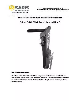
5253 Verona Road Madison WI 53711 Phone: 800-783-7257 • E-mail: info@sarisinfrastruture.com www.sarisinfrastructure.com _____________________________________________________________________________________________ Installation Instructions for Saris Infrastructure Deluxe Public Work Stand – Manual Rev. D Street/Trail Setback Minimum: The setback for the Deluxe Public Work Stand is dependent on whether there is a Wheel Chock installed or not. See
figure 1 and 2 for dimensions. If bra
figure 1 and 2 for dimensions. If branding is part of the installation, the back of the repair stand should face the trail. If a Hoop Sign is installed, its location should be positioned based on each site. 2 Site Layout for Saris Infrastructure Deluxe Public Work Stand Minimum Space Requirements The minimum space requirements for the Deluxe Public Work Stand are dependent on whether there is a Wheel Chock installed or not. See figure 1 and 2 for minimum space requirement dimensions. If branding is part of the installation, the back of the repair stand should face the trail. Figure 1: Minimum space requirements (w
ithout Wheel Chock) Figure 2: Mi
ithout Wheel Chock) Figure 2: Minimum space requirements (with Wheel Chock) 3 Setbacks It is recommended that all equipment is spaced a minimum of 60” from an adjoining street or cycle path. Pad size If you are pouring a new concrete pad, these are two recommended sizes. Option 1 is 36” x 36” x 4”, option 2 is a 16” diameter cylinder that is 36” long. Figure 3: Recommended new pad configurations 4 Tools Needed for Installation (Installer Provides) Tape Measure ½” Masonry Drill Bit Drill (Hammer drill recommended) Hammer 3/8” drive ratchet and extension 14mm (9/16”)
socket 14mm (9/16”) wrench 19mm (
socket 14mm (9/16”) wrench 19mm (3/4”) wrench Marker or Pencil SAE hex key set Level Tools for Installation Provided with Equipment Anchor Set Tool *Penta Security Socket Concrete Anchor 2 button head hex bolts 2 threaded concrete anchor studs 2 Penta nuts (use with anchor studs) *DO NOT THROW AWAY THE PENTA SOCKET AFTER COMPLETING THE INSTALLATION. YOU WILL NEED IT TO REMOVE THE EQUIPMENT IF THAT IS NECESSARY. 5 **All manual pumps also come with a tube of lubrication for the pump’s piston rod. See Appendix A for Saris Infrastructure’s recommended
preventative maintenance schedule.
preventative maintenance schedule. Installation 1. The Deluxe Public Work Stand ships in two separate boxes. If you purchased a pump or a Wheel Chock, those will be in extra boxes as well. Remove all parts from their boxes. 2. If your installation does not include a pump, skip to step 8. Tighten the threaded elbow fitting and the external hose onto the repair stand using a 14mm (9/16”) wrench Threaded elbow fitting External hose 3. Connect the internal air hose to the elbow fitting by pressing it in until it bottoms out.
Internal air hose 6
Internal air hose 6 4. Route the internal air hose into the side groove of the repair stand and have it exit at the pump mounting location (three circular holes). Connect the non-threaded elbow fitting to the hose by pressing it in until it bottoms out. 5. Prepare the pump by placing the long carriage bolts into the square holes on the mounting bracket and then insert into the round repair stand mounting holes. Mounting bracket Pump outlet 7 Thin Jam Nut Thin Jam Nut on Carriage Bolt 6. Tighten the Thin Jam Nuts onto
the carriage bolts using a using a 14mm
the carriage bolts using a using a 14mm (9/16”) and connect the elbow to the pump outlet. Next, install the weight guard and route the internal air line through the slot. Thin Jam Nuts on Carriage Bolts Weight guard 7. Thread the locknuts onto the carriage bolts using a 14mm (9/16”) socket, extension, and ratchet Lock nut Lock nut on carriage bolt 8 8. If you are not installing a Wheel Chock, skip to step 9. Insert carriage bolts into the square mounting holes on the Wheel Chock and then insert into Wheel Chock mounting holes on the
side of the repair stand. Tighten the
side of the repair stand. Tighten the lock nuts using a 14mm (9/16”) socket. Locknut 9. Install the plastic cover. Start by feeding the bottom edges of the cover into the side grooves at the top of the stand and slide it down. Be sure it is seated into the slot at the base. 9 10. Install tool assemblies into base inserting the weights first. The tool assemblies and tool assembly carriage may be heavy for the person performing the installation. Avoid pinching fingers or hands when setting the tool carriage into place.
11. Check the cable routing to
11. Check the cable routing to ensure that no tools are tangled. It is recommended that you pull on each tool to check for smooth operation. 10 12. Tighten the large nut that secures the tool assembly carriage to the stand using a 19mm (3/4”) wrench. 13. Install aluminum casting and then the top cap. 11 Aluminum casting Top cap 14. Install and tighten the 2 front Penta nuts and Penta stud. Check the tightness twice of each. Do not over tighten these bolts. Front Penta nuts 12 Penta stud 15. Plac
e the repair stand in the desired locati
e the repair stand in the desired location (see setbacks on page 2). Use a marker or pencil to outline the holes of the flange onto the base material. We recommend checking the hole locations after each new anchor is placed. Ensure the holes are at least 6” away from any cracks in the base material. 16. The concrete anchor (a.k.a “drop in anchor”) is a female anchor designed for use in solid concrete only and cannot be used in brick or block base material. The anchor size is designated by the inside diameter of the anchor. The Saris Infrastructure Public Work Stand and Manual Pumps come with 3/8”-16 anchors. The diam
eter of the hole to be drilled is the
eter of the hole to be drilled is the same size as the outside diameter of the anchor which is ½”. 17. When fastening to solid concrete with a drop in anchor, a hole must first be drilled into the concrete. A hammer drill should be used as it will drill the best quality hole. Once the bit is inserted into the hammer drill, the depth of the hole to be drilled can easily be set by using the depth gauge on the drill or by wrapping the bit with tape at the required depth. We recommend a drill depth of 1-5/8” deep so that the anchor just sets down flush with the surface. 18. Before starting to drill the hole, it is important that ey
e and ear protection are used. Make sur
e and ear protection are used. Make sure the hammer drill is in the hammer mode and start drilling your hole. 13 Continue drilling until the tape on the bit or the drill gauge meets the base material- this means that the required depth has been reached. 19. Before proceeding with installation, the hole must be cleaned of all concrete dust to ensure proper fastening. Use a wire brush, a vacuum or compressed air to clean out the hole completely. 20. Next, insert the drop in anchor with the open side up. Tap lightly to get the anchor flush with the base material. 21. Now, take the setting tool and insert it into the anchor.
Strike the setting tool with the hamm
Strike the setting tool with the hammer until the lip of the anchor touches the lip of the setting tool. This will ensure the anchor is properly set. 14 22. For the Public Work Stand - place the stand over the 4 anchors. You will be using 2 studs for the Penta nuts and 2 button head hex bolts (opposite sides from each other). You will thread the studs into the anchors prior to installing the Penta nuts using the Penta socket. Use the hex wrench to tighten the button head hex bolts. 23. Before tightening everything down, make sure the stand and/or pump are level and adjust accordingly with washers underneath the fla
nges. 24. Ensure all tools retra
nges. 24. Ensure all tools retract and extend properly. Cable routing could have shifted during shipping and needs to be adjusted by removing the repair stand top. Congrats! You’re finished! Appendix A Maintenance Item Frequency Time required Pump head renewal Every 3-12 months as required 2 minutes Lubrication of pump rod Every 6-12 months as required 2 minutes Full pump overhaul Every 24+ months as required 30 minutes Tool Replacement As required 15 minutes *For instructions on how to perform these tasks, please contact sales@sarisinfrastructure.com for a copy of our High Security pump service man