
1BYGugi2TableofContents2Patio Slab 2Timber Structural Calculations2Column Stability 7Wind Loading Calculations 10Frame anchoring Calculations from Wind Load Tension and Lateral Loading10APPENDIX A ID: 860887
Download Pdf The PPT/PDF document "Building Background" is the property of its rightful owner. Permission is granted to download and print the materials on this web site for personal, non-commercial use only, and to display it on your personal computer provided you do not modify the materials and that you retain all copyright notices contained in the materials. By downloading content from our website, you accept the terms of this agreement.


1 1 BY G u g i
1 BY G u g i 2 T a b l e o f C o n t e n t s Building Background â¦â¦â¦â¦â¦â¦â¦â¦â¦â¦â¦â¦â¦â¦â¦â¦â¦â¦â¦â¦â¦â¦â¦â¦â¦. 2 Patio Slab â¦â¦â¦â¦â¦â¦â¦â¦â¦â¦â¦â¦â¦â¦â¦â¦â¦â¦â¦â¦â¦â¦â¦â¦â¦ â¦â¦â¦â¦â¦â¦â¦2 Timber Structural Calculations â¦â¦â¦â¦â¦â¦â¦â¦â¦â¦â¦â¦â¦â¦â¦â¦â¦â¦â¦â¦â¦. 2 Column Stability â¦â¦â¦â¦â¦â¦â¦â¦â¦â¦â¦â¦â¦â¦â¦â¦â¦â¦â¦â¦â¦â¦â¦â¦â¦ â¦â¦â¦.. 7 Wind Loading Calculations â¦â¦â¦â¦â¦â¦â¦â¦â¦â¦â¦â¦â¦â¦â¦â¦â¦â¦â¦â¦â¦â¦â¦10 Frame anchoring Calculations from Wind Load Tension and Lateral Loading â¦â¦â¦â¦â¦â¦â¦â¦â¦â¦â¦â¦â¦â¦â¦â¦â¦â¦â¦â¦â¦â¦â¦â¦â¦ â¦â¦â¦â¦â¦â¦â¦ ⦠..10 APPENDIX A Design D
2 r awings â¦â¦ â¦â¦â¦â¦â¦â¦â¦â¦
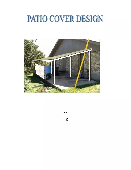
r awings â¦â¦ â¦â¦â¦â¦â¦â¦â¦â¦â¦â¦â¦â¦â¦â¦â¦â¦â¦â¦â¦16 APPENDIX B Materialsâ¦â¦â¦â¦â¦â¦â¦â¦â¦â¦â¦â¦â¦â¦â¦â¦â¦â¦â¦â¦â¦â¦â¦â¦â¦21 BUILDING BACKGROUND T h e s t r u c t u r e was established in 1 9 7 8 . The building is about 40 years old and is a single stoiry wood frame structure with an external veneer made of rock. The foundation of the building r e sts on limestone 3 and free from expansive soils. No structural deficiencies appear to exist in the superstructure and the foundation. PA TIO SLAB An attaché slab exists on the north side of the structure that extends 12 feet further on the longer axis of the building and has a length of 40 feet. It is not known about the presence, extent or absence of reinfo
3 rcement of the slab. The slab is
rcement of the slab. The slab is currently without an canopy and surrounded on the eastern position with trees. The slab appears I a reasonable condition except for contraction/tension cracks running at 45 degree angle across the slab wher e a stair pedestrian comes in contact with the s lab. There was no control joints placed during the pour of the slab. Proir to this design, a CMU wall about 4 feet in height has been placed that extended alng bthe perimeter of the slan b to about 10 feet of the northern perimeter. The CMU wall is not reinforced The objective of the design is to extend a partially open roof over 75% of the slab, that rxpends from the eastern corner to about four feet from the entrance door. The canopy shall be of NO: 2 grdae structu ral timb
4 er. Ro of loading is expected to be
er. Ro of loading is expected to be minimal as it is not going to be subject to loading from equipment or personnel . A load of 10 PSF is exp ected to be sufficient to effectively bear trhe load of four persons for repair. WOOD FRAME STRUCTURAL CALCUL ATIONS Readil y available timber species is the southern pine or yellow pine in Southern Texas. This woood is generally used for residential framing. The engineering characteristics of this type of wood are: Modulus of Elasticity (E): 1100000 psi Bending Strength ( Fb: ) 1336.87 psi Bearing Strength (Fcp): 335 psi Shear Strength (Fv): 135 psi The following plan has been drafted as dimensions of the canopy . The post locations are shown. The wood rafter and joist are be placed within the dimensions of the post s.
5 Post A and past Be a r e about 8 inches
Post A and past Be a r e about 8 inches away from the CMU wall Long length = 24 feet Width between post center to center c - c = 9 feet 4 The American Wood Council has extensive engineering information . The engineering calvulations for deflection, shear, torsion, can be done manually , however a very good AWC furnished calculato r is available that can be used to calculate joist span and spacing calculations based on wood type used. Lumber design values used to calculate maximum horizontal spans include modulus of elasticity (E), bending strength (Fb), and shear strength (Fv). B earing strength in compression perpendicular to grain (Fcp) is used to determine the minimum required bearing length at each end of joists and rafters. Calculated spans incorporate design value
6 adjustments appropriate for repetitive
adjustments appropriate for repetitive - member use (Cr = 1.15) , duration of load (CD), lumber size (CF), wet service conditions (CM), and incised lumber (Ci). The 2005 National Design Specification® for Wood Construction (NDS®) specifies appropriate magnitudes for lumber design values and adjustment factors. Maximum horizontal joist and rafter spans are taken as the smallest span (L) calculated from the following three formulas: (A) 16 12 8.5 28 25 till past door 11.5 12 9 9 Figure 1 A B 5 based on bending strength (Fb) where s = spacing between joists or rafters Sx = section modulus for strong - axis bendin g of joist or rafter wT = total distributed load (D + L, or D + Lr, or D + S) supported by joist or rafter, in terms of load per unit a
7 rea (B) Based on deflection limi
Based
on deflection limi")
rea (B) Based on deflection limit and modulus of elasticity ( E ) where Ix = strong axis moment of inertia for joist or rafter wL = distributed live load (L or Lr) or distributed snow load (S) supported by joist or rafter, in terms of load per unit area deflection constant = constant term in denominator of deflection limit (e.g., L/360) . Here L/240 shall be used as ot much loading is anticipated (C) based on shear strength ( F v ) where A = cross - sectional area of joist or rafter BEARING LENGTH The minimum required bearing length (lb) at each end of a j oist or rafter is determined from the following formula: Where t=thickness of joist or rafter Using the equation, as the designer, joist and rafter sizes chosen aree 9 feet center to center of the
8 4 by 4 treated wood columns (posts)..")
4 by 4 treated wood columns (posts). The calculator inpu t is as shown in table 2 6 The calculator gives an allowable span is 9â - 11â which is OK for this span design for joists For t he rafter , with about 12 iches center to center on which the joists will be attached in perpendicular. Calculations show that a single 4 by 10 (No: 2 structural wood lumber of southern pine) is minimally sufficient. Figure 2: Calculator input 7 These are conservative values. In m y professional opinion two 2*6 lumber rafter can be used to support the joists on either end. C OLUMN STABILITY ) The slenderness ratio Le/d for solid column shall not exceed 50 for service load and shall not exceed 75 for construction. Le=Ke ï´ L is effective length of column, Ke i
9 s slenderness ratio, L is unsupported le
s slenderness ratio, L is unsupported length of column. For rectangular section, Le/d shall be evaluated in both directions. Maximum compressive stress, fc must not exceed allowable stress parallel to grain, Fâc = Fc*CD*CM*Ct*CF*Cp Where Fc is allo wable bending stress in NDS supplement. CD is load duration factor, (see beam design) CM is wet service factor, (use when moisture of timber is higher than 19%) Ct is temperature factor, (when timber is used in temperature higher than 150 ï° F) CF is size factor, (apply only to visually graded sawn lumber members, and to round timber bending members, not apply simultaneously with Cv for glued laminated timber) Cp is column stability factor (see below) 8 According to NDS 3.7.1, column stabilit y factor shall be determined a
10 s Fully supported laterally throughout
s Fully supported laterally throughout its length, Cp=1. Otherwise, Cp shall be calculated as Fc*=Compressive design value in NDS tables multiplied by all other adjustment factor except Cp, FcE= KcE ï´ Eâ/(Le/d)2, KcE=0.3 for visually graded lumber and machine evaluated lumber, (note: KcE=0.418 for machine stress rated lumber and glued laminated timber), C=0.8 for sawn lumber, (note: c = 0.85 for round timber piles and 0.9 for glued laminated timber). Calculation: Attempt 4 by 4 , 10 foot column Southern pine, moisture less than 19%, used in normal room temperature. Floor area supported by column: A = 30 ft2 Unsupported length of column, L = 10 ft Floor live load: WL = 10 psf Floor dead load: WD = 5 psf Superimposed dea d load: WSD = 5 psf Calc
11 ulation step 1. Select southern pine, 4
ulation step 1. Select southern pine, 4"x4" stud grade, d = 3.5 in Actual cross section: Ac = 12.25 in2. Allowable compressive stress parallel to grain: Fc = 975 psi Calculation step 2. Calculate slenderness ratio: Ke = 1, Le =K e ï´ L = 10 ft, Le/d = 34 50 OK Calculation step 3 . Calculate compressive stress with load duration factor 9 Load duration factor for dead load: CD = 0.9 Load duration factors for live load: CD = 1.0 (Use 1 per NDS) Calculate Design load: P = [WD + WSD+ WL ] ï´ A =[5 + 5+ 10] ï´ 30= 600 lb Column compressive stress, fc =P/Ac = 600/12.25= 50 p si Calculation step 4. Calculate allowable stress without Cp. CM =1, Ct =1, Cf =1 Fc* = Fc ï´ CM ï´ Ct ï´ CF = 975 psi Calculation step 5. Calculate elasticity modulus for
12 this wood species Eâ =E ï´ CM ï´
this wood species Eâ =E ï´ CM ï´ Ct = 1.4 ï´ 106 psi Calculation step 6. Calculate FcE KcE =0.3 FcE = KcE*Eâ/(Le/d)2= 1*1.4 ï´ 106 /(34)2 = 1211 psi Calculation step 7. Calculate Cp c = 0.8 C p = Cp = 0. 76 Calculation step 8. Calculate allowable compressive stress Fâc = Fc* ï´ Cp = 975 ï´ 0.76= 741 psi � fc = 293.8 psi (in NDS tables) The whole column can support 3.5*741 psi = 2,593 lbs . The patio roof is not expected to be subject to live load except occasion a few persons for r epair, which will be far less the column compressive ability. Column O.K. 10 WIND LOADING CALCULATIONS The manual calculations are ex
13 tensive and tedious. Therefore a calcul
tensive and tedious. Therefore a calculator input has been used o generate the negative and positive pressures on the open roof. The posive wind loading from 80 mile per hour winds is used (although 90mph is the code) as the roof shall be surrounded by trees. Dead load and occasion temporary live loads from individual stepping on the roof for repair is minimal. A higher negative wind loading is used as an conservative measure with a safety factor of 23/18 =1.27 . The structure is a monoslope with partial enclosure of CMY walls about 4.5 foot in heights . Column base plate/ anchoring stability calculations are developed further based on tension loading base d on wind loading calculations. The area is going to be used for external to building gas based cooking. FRAME ANCHORING CALCULATIONS
14 FROM WIND LOAD TENSION AND LATERAL LOADI
FROM WIND LOAD TENSION AND LATERAL LOADINGS (ASCE - 05, Appendix D Building Code) The support columns are to be placed a t 12 feet separation along the slab facing the structure and at 9 feet CC towards opposite of boiling superstructure . As each column s upports a portion of the loads per tributary area for aech column. An approximate tributary for each columns is 6*5 for central columns . The tension wind, conservative to actual wind loads is approximated as 23 psf (pounds per square foot). That gives a tensile wind loading of per column Therefore: 5 ft *6 ft *23 = 690 psf vertical tensile uplift pressure on column per tribu tary area for columns 11 Although the tributary area of columns âAÍ abd âBâ are less, the approximation will still hold for the larger
15 tributary areas. \ BoltsÍ Â¾â h
tributary areas. \ BoltsÍ Â¾â headed hex bold F uta : = 70 ,000 Embedment in grout padsÍ = 6 â Concrete Fâc Í= 4000 psi Slab thickness := 18 inches Loads in vertical tension: = 7 00 lbs on column Load in shear in x - direction: = 1000 lbs Load i n shear in y - direction: = 1000 lbs Bolts at x - y distance = 4â Top EdgeÍ= 15â Bottom EdgeÍ= 15â Left EdgeÍ= 15â Right EdgeÍ= 15â 6 â 700 18 â 1000 lbs 1000 lbs 12 Bolt Tension (D.5.1 ASCE 315 ) Ï N sa = Ï n A se .f uta â¦â¦â¦â¦â¦â¦â¦â¦â¦â¦â¦â¦â¦â¦â¦â¦â¦..(a) where bolt area and f is and Ï is the strength reduction factor, N sa is strength of group of anchors, n is the number of anchors, f uta specifie d tensile strength of single anchor f
16 rom manufacturers catalogue Ï = 0.7
rom manufacturers catalogue Ï = 0.7 , n = 4 , A se = 0.334 in 2 , f uta = 70 ksi Ï N sa = Ï n A se .f uta =47.5 kips Concrete Breakout (D.5.2, ASCE 318) Ï N cb = Ï (A nc /A nco ) Ψ ec Ψ ed Ψ c Ψ cp N b â¦â¦â¦â¦â¦â¦â¦â¦â¦â¦â¦â¦â¦â¦â¦â¦â¦â¦â¦â¦â¦(b) Ï = Modification factor for concrete breakout strength = 0.7 A nc = Projected concrete breakout area = 484 in2 A nco = Total projected shear failure area = 324 in2 Ψ ec = Modification factor for an anchor group loaded eccentrically = 1.0 Tributary Area D Tributary Area A Tributary Area B Tributary Area C Tributary Area E Tributary Area F 13 Ψ ed = Modification factor for edge effect in shear = 1.0 Ψ c = Modification factor based on presence or ab
17 sence of cracks in concrete = 1.0 Ψ
sence of cracks in concrete = 1.0 Ψ cp = Modification factor for post weld type of anchor = 1.0 N b = Modification factor for breakout strength of single anchor in shear = 22,3 kips H ef = Embedment depth = 6â K c = 24 Ï N cb = 23.3 kips Pullout (D.5.3 , ASCE 318) Ï N pn = Ï Î¨ c N p â¦â¦â¦â¦â¦â¦â¦â¦â¦â¦â¦â¦â¦â¦â¦â¦â¦â¦â¦â¦â¦â¦..(c) Ï = strength reduction factor in pull out strength = 0.7 Ψ c = Modification factor for breakout strength in presence of concrete cracks = 1.0 N p = 2 2.2 kips Ï N pn = 62.1 kips Side Face Blowout (D.5.4 , ASCE 318) Ï N sb = Ï (1+s/(6C a1 (A rg fâ c )^ 0.5 â¦â¦â¦â¦â¦â¦â¦â¦â¦â¦â¦â¦â¦â¦â¦â¦â¦â¦.(d) Ï = 0.7 C a1 = 15 Ï N sb = Not Applicable Shear Calculation X -
18 Direction Bolt Shear (D.6.1 , ASCE 318
Direction Bolt Shear (D.6.1 , ASCE 318) Ï V sa = Ï n A se f uta ⦠â¦â¦â¦â¦â¦â¦â¦â¦â¦â¦â¦â¦â¦â¦â¦â¦..(e) Ï = 0.65 n= 4 A se =0.334 in2 f uta = 70 ksi Ï V sa = 24.7 14 Shear Calculation X - Direction Concrete Breakout (D.6.2 , ASCE 318) Ï V cb = Ï (A Vc /A Vco ) Ψ ec Ψ ed Ψ c Ψ cp V b â¦â¦â¦â¦â¦â¦â¦â¦â¦â¦â¦â¦â¦â¦â¦â¦â¦â¦â¦â¦â¦ (f ) Ï = 0.7 A V c = Projected concrete breakout area = 612 in2 A V co = Total projected shear failure area = 648 in2 Ψ ec = Modification factor for an anchor group loaded eccentrically = 1.0 Ψ ed = Modification factor for edge effect in shear = 1.0 Ψ c = Modification factor based on presence or absence of cracks in concrete = 1.0 Ψ cp = Modification factor for
19 post weld type of anchor = 1.0 V b =
post weld type of anchor = 1.0 V b = Modification factor for breakout strength of single anchor in shear = 24.2 kips H ef = Embedment depth = 6â C a1 = 12 â Ï V cb =27.7 kips Shear Calculation X - Direction Concrete pry out (D.6.3 , ASCE 318) Ï V cp = Ï n K cp N cb â¦â¦â¦â¦â¦â¦â¦â¦â¦â¦â¦â¦â¦â¦â¦â¦â¦..(g) Ï = 0.7 K cp = 2 Ï V cp = 46.7 kips Shear Calculation y - Direction Bolt Shear (D.6.1, ASCE 318) Ï V sa = Ï n A se f uta â¦â¦â¦â¦â¦â¦â¦â¦â¦â¦â¦â¦â¦â¦â¦â¦â¦ ..(h ) Ï = 0.65 n= 4 A se =0.334 in2 f uta = 75 ksi Ï V sa = 24.7 15 Shear Calculation X - Direction Concrete Breakout (D.6.2 , ASCE 318) Ï V cb = Ï (A Vc /A Vco ) Ψ ec Ψ ed Ψ c Ψ cp V b â¦â¦â¦â¦â¦
20 â¦â¦â¦â¦â¦â¦â¦â¦â¦â¦â¦â¦â¦â
â¦â¦â¦â¦â¦â¦â¦â¦â¦â¦â¦â¦â¦â¦â¦â¦(f) Ï = 0.7 A V c = Projected concrete breakout area = 612 in2 A V co = Total projected shear failure area = 648 in2 Ψ ec = Modification factor for an anchor group loaded eccentrically = 1.0 Ψ ed = Modification factor for edge effect in shear = 0.950 Ψ c = Modification factor based on presence or absence of cracks in concrete = 1.0 Ψ cp = Modification factor for post weld type of anchor = 1.0 V b = Modification factor for breakout strength of single anchor in shear = 24.2 kips H ef = Embedment depth = 6â C a1 = 12 â (&Psih = 1.0) Ï V cb = 27.7 kips Shear Calculation Y - Direction Concrete pry out (D.6.3 , ASCE 318) Ï V cp = Ï n K cp N cb â¦â¦â¦â¦â¦â¦â¦â¦â¦â¦â¦â¦â¦â¦â¦â¦â¦..(g) Ï
21 = 0.7 K cp = 2 Ï V cp = 46.7
= 0.7 K cp = 2 Ï V cp = 46.7 kips Results Summery X and Y interaction = 0.0086 Tensile Capacity Ï N n = 23.3 kips Breakout controls Shear X Capacity Ï V nx = 24.7 Kips Breakout controls Shear Y Capacity Ï V ny = 24.7 Kips Breakout controls Design OK 16 APPENDIX A Design Drawings 17 18 APPENDIX B Materials (Partial List) 19 1. Rafters 2 by 4 Structural wood #2 2. Psts (3) 4 by 4, 10 feet high and (3) 10.5 ft high, treated lumber 3. Post holders = 6 4. Hex bolts = 24 5. Beams = four 2 by 10 , each side
22 2 by 10 coupled or one 4 by 10 each sid
2 by 10 coupled or one 4 by 10 each side 6. Apoxy 7. Hammer drill 8. Blower 9. Self drilling nails 10. Connectors 11. Drill 16 ” c - c 12 10’ span between columns 11’ - 5” span between columns 4 by 4 Column 2 by 4 by 12 Joist 4 by 46by 12 Beam 4 by 46by 12 Beam 2 by 6 by 12 Beam Non Load Bearing Connection Building 4 by 6 4 by 6 Flashing Corrugated roof Eav e= 1 ’ - 5 “ Setback 1’ - 0 ” 9’ 2 by 4 Joist, 16” spacing 1’ - 4” Eave= 1’ - 9 “ 12 - 6 12 4 by 6 by 12 Beam 4 by 4 4 by 4 4 by 4 11.5 10 4 by 6 by 12 Beam 12 ’ 1 ’ - 5 ” ’ - 6 ” T - Connection