
To Inertial Confinement Fusion 27 th IAEA Fusion Energy Conference Gandhinagar Gujarat India October 2227 2018 R E Olson R J Leeper S H Batha P A Bradley B M Haines J L Kline R R Peterson S A Yi and A B ID: 1021063
Download Presentation The PPT/PDF document "LA-UR-18-29741 Liquid DT Layer Approach" is the property of its rightful owner. Permission is granted to download and print the materials on this web site for personal, non-commercial use only, and to display it on your personal computer provided you do not modify the materials and that you retain all copyright notices contained in the materials. By downloading content from our website, you accept the terms of this agreement.


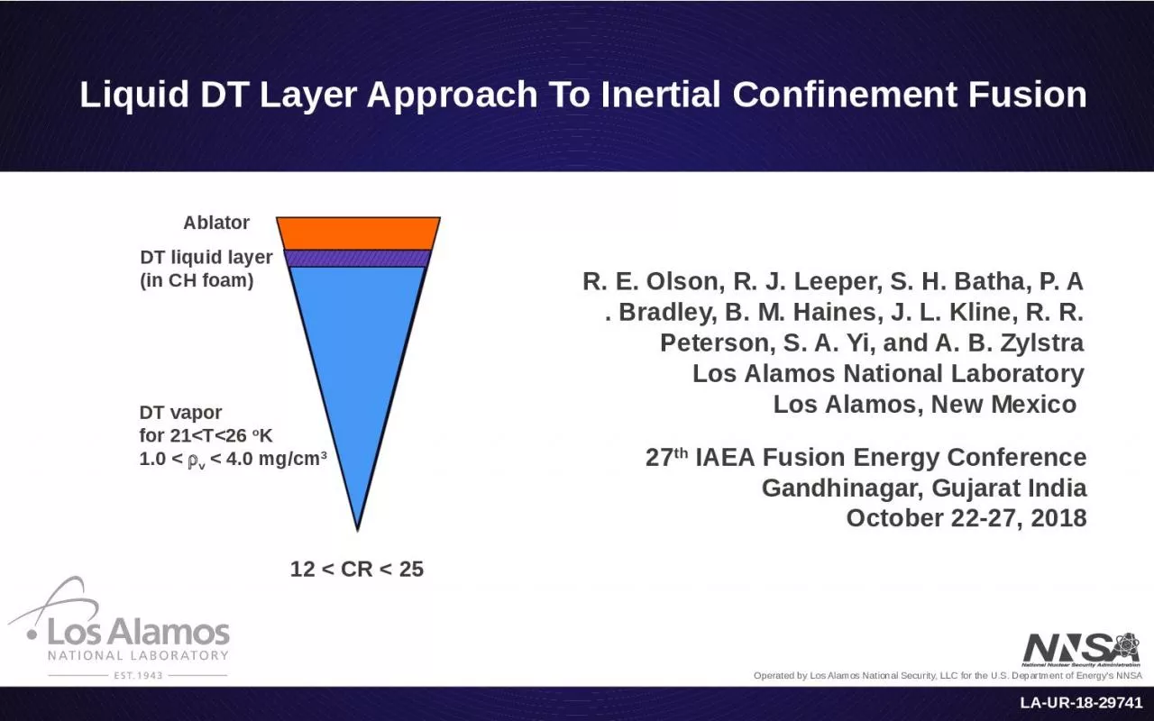
1. LA-UR-18-29741Liquid DT Layer Approach To Inertial Confinement Fusion 27th IAEA Fusion Energy ConferenceGandhinagar, Gujarat IndiaOctober 22-27, 2018R. E. Olson, R. J. Leeper, S. H. Batha, P. A . Bradley, B. M. Haines, J. L. Kline, R. R. Peterson, S. A. Yi, and A. B. ZylstraLos Alamos National LaboratoryLos Alamos, New Mexico 12 < CR < 25DT vaporfor 21<T<26 oK1.0 < rv < 4.0 mg/cm3DT liquid layer (in CH foam)Ablator
2. 10/16/18 | 2Los Alamos National LaboratoryDT ice layer implosions have a high hot spot convergence ratio, CR>30.Recent cryogenic liquid DT layer implosions at the NIF demonstrate the ability to control hot spot CR’s in the range of 12<CR<20. At low CR, DT layered implosion performance is well predicted by radiation-hydrodynamics simulations, but as CR increases, our understanding of hot spot formation decreases.There are potential advantages for a liquid DT layered implosion with reduced hot spot CR (CR<20).Liquid DT Layer Approach to ICF Hot Spot Formation some key points:
3. 10/16/18 | 3Los Alamos National LaboratoryA liquid DT layer allows for a higher vapor density compared to a DT ice layer, the ability to create a hot spot from the vapor, and flexibility in hot spot CR.With reduced CR, hot spot formation is expected to be more robust to instabilities and asymmetries than high CR ice layer implosions.With reduced CR, the hot spot pressure required for self-heating is reduced, and the implosion velocity and fuel adiabat requirements are relaxed. (A trade-off is, that with larger hot spot size, the hot spot energy requirement for self-heating is increased.)Potential advantages of a liquid DT layerkey advantages:
4. 10/16/18 | 4Los Alamos National LaboratoryLos Alamos National LaboratoryA liquid DT layer allows for selecting a CR by adjusting the cryogenic fielding temperature.CR > 30 DT vaporfor T<19 oK rv < 0.4 mg/cm3DT ice layerAblator 12 < CR < 25DT vaporfor 21<T<26 oK1.0 < rv < 4.0 mg/cm3DT liquid layer (in CH foam)Ablator advantages of a liquid DT layer:*R. E. Olson and R. J. Leeper, “Alternative hot spot formation techniques using liquid DT layer ICF capsules”, Phys. Plasmas 20, 092705 (2013).
5. 10/16/18 | 5Los Alamos National LaboratoryDT layer implosions with reduced CR will have improved robustness to instability growth and distortions related to engineering features.hot spot CR2D yield / 1D yieldDT liquid layers(wetted foam)DT ice layerBrian Haines RAGE simulations*: Variations on a full scale HDC wetted foam capsule design including detailed and well-resolved models for the capsule fill tube, support tent, surface roughness, and predicted asymmetries in the X ray drive.*B. Haines et al., “The effects of convergence ratio on the implosion behavior of DT layered ICF capsules,” Phys. Plasmas 24, 072709 (2017). advantages of a liquid DT layer:
6. 10/16/18 | 6Los Alamos National LaboratoryRecent experiments on NIF have demonstrated liquid layer implosions NIF sub-scale liquid layer experiments:CH foam-linedHDC capsuleAu near-vacuum hohlraum< 900 kJ 3-shock NIF laser pulse J. Biener et al., “A new approach to foam-lined indirect-drive NIF ignition targets”, Nuclear Fusion 52, 062001 (2012).T. Braun et al., “Supercritical drying of wet gel layers generated inside ICF ablator shells”, Fusion Sci. Technol. 73, 229 (2018).C. Walters et al., “D2 and D-T liquid-layer target shots at the National Ignition Facility”, Fusion Sci. Technol. 73, 305 (2018).
7. 10/16/18 | 7Fill tubeCold FingerFrozen plugVery top level procedure:Fill target (liquid wicks into foam)Fix amount of fuel by freezing a plug in the fill tubeHold target and plug temperatures through the shotDT (thermal impedance)The NIF cryo team developed thermal designs, along with a process to wick the liquid DT (or D2) into the foam layer. liquid DT (or D2) layerRi = 815 mm Ro = 907 mm HDC ablatorliquid layer capsule575 Near-Vacuum HohlraumTcryo = 20-26 oKNIF sub-scale liquid layer experiments:Los Alamos National LaboratoryC. Walters et al., “D2 and D-T liquid-layer target shots at the National Ignition Facility”, Fusion Sci. Technol. 73, 305 (2018).
8. 10/16/18 | 8Los Alamos National LaboratoryThe initial experiments successfully demonstrated the ability to select a layered implosion CR in the range of 12<CR<20. CR = 12T = 26 oK, ρvapor = 4 mg/cm3 (NIF shot N160421)CR = 17 T = 24 oK, ρvapor = 3 mg/cm3 (NIF shot N160626)CR = 20T = 21 oK, ρvapor = 1 mg/cm3 (NIF shot N161204)R. E. Olson, R. J. Leeper et al., “First Liquid Layer ICF Implosions at the NIF”, Phys. Rev. Lett. 117, 245001 (2016).NIF sub-scale liquid layer experiments:
9. 10/16/18 | 9Los Alamos National LaboratoryFor CR = 12, the hot spot formation is understood – demonstrated by the agreement between experimental data and simulations.NIF sub-scale liquid layer experiments:*2D RAGE simulations including drive asymmetry, tent, fill tube, capsule surface roughness, and low-mode foam shape asymmetries.*The agreement of the DT ion temperature and the DD ion temperature is an important feature of this DT liquid layer experiment. It is usually found in DT ice layer implosions that the measured DT ion temperature exceeds the expectation from simulationsan indication of inefficiency in hotspot formation due to incomplete stagnation and residual kinetic energy effects.experimentsimulation*DT neutrons (1014) 4.5 + 0.1 4.9peak burn time (ns) 8.49 + 0.03 8.5DT Tion (keV) 3.2 + 0.1 3.3DD Tion (keV) 3.0 + 0.2 3.0burn width (ps) 313 + 30 275hot spot radius (mm) X ray image 64.7 + 4.7 65 neutron image 50.6 + 2.2 47N160421 implosion metricsexperimentsimulationR. E. Olson, R. J. Leeper et al., “First Liquid Layer ICF Implosions at the NIF”, Phys. Rev. Lett. 117, 245001 (2016).
10. 10/16/18 | 10Los Alamos National LaboratoryThe data trends might be explained by: reduced hydrodynamic coupling efficiency due to 3D effects1 and/oranomalously enhanced thermal conductivity in the DT layer2Although the expected CR control was demonstrated, the observed over calculated yield decreased dramatically as CR was increased.1B. M. Haines et al., “3D simulations of NIF wetted foam experiments to understand the transition from 2D to 3D flow behavior,” Inertial Fusion Sciences and Application Proceedings (2017) 2A. B. Zylstra et al., “Variable convergence liquid layer implosions on the National Ignition Facility, Phys. Plasmas 25, 056304 (2018)2D RAGE simulations including drive asymmetry, tent, fill tube, capsule surface roughness, and low-mode foam shape asymmetries. NIF sub-scale liquid layer experiments:
11. There are tradeoffs involved in high CR ice layer and reduced CR liquid layer designs10/16/18 | 11Los Alamos National LaboratoryThe hot spot pressure required for self-heating is reduced if the CR is reduced (hot spot radius is increased).If the hot spot pressure requirement for self-heating is reduced, the implosion velocity and fuel adiabat requirements are relaxed.With larger hot spot size, the hot spot energy requirement for self-heating is increased.Although there is a penalty to be paid in energy investment for a larger hot spot, it should be noted that there is a significant benefit in the hot spot alpha particle energy production, which also increases with the square of the hot spot radius.
12. 10/16/18 | 12Los Alamos National LaboratoryThe hot spot pressure required for self-heating is reduced if the CR is reduced (hot spot radius is increased).Hot Spot Radius (mm)Hot Spot Pressure (Gbar)(required for self-heating)NIC point design(ice layer, CR ~ 34)Prhs a Rhs-1 a CRreduced CRtradeoffs between ice and liquid layer designs:
13. 10/16/18 | 13Los Alamos National LaboratoryIf the hot spot pressure requirement for self-heating is reduced, the implosion velocity and fuel adiabat requirements are relaxed.Prhs a v5 / b1.5 (isobaric stagnation)tradeoffs between ice and liquid layer designs:
14. 10/16/18 | 14Los Alamos National LaboratoryWith larger hot spot size, the hot spot energy requirement for self-heating is increased.tradeoffs between ice and liquid layer designs:Although there is a penalty to be paid in energy investment for a larger hot spot, it should be noted that there is a significant benefit in the hot spot alpha particle energy production, which also increases with the square of the hot spot radius.Ehs a Rhs2 a CR-2reduced CR (or larger capsules)Hot Spot Energy (kJ)(required for self-heating)( at fixed rr )
15. 10/16/18 | 15Los Alamos National LaboratoryLiquid DT layers offer a modest Convergence Ratio (CR) path to an ICF burning plasma. However, reduced CR requires more capsule absorbed energy.adiabat = 1.0(ideal limit)1.52.02.53.03.56.05.55.04.54.0(assumes 1D-like behavior, rRtot = 2 g/cm2, 10% hydro-coupling) DT liquid layers, CR ~ 20, Ecap ~ 350 kJDT ice layers,CR ~ 35, Ecap ~ 150 kJCapsule Absorbed Energy Requirement (kJ)Hot Spot Convergence Ratiotradeoffs between ice and liquid layer designs:
16. 10/16/18 | 16Los Alamos National Laboratory10/16/18 | 16Los Alamos National LaboratoryLiquid DT layers provide a reduced CR approach to ICF hot spot formation.flexibility in hot spot CR in the range of 12<CR<25the ability to create a hot spot from the central vaporimproved robustness to instability growth, distortions related to engineering features, and drive asymmetries.The hot spot pressure required for self-heating is reduced if the CR is reduced (hot spot radius is increased).DT liquid layer implosions and CR control have been demonstrated in sub-scale NIF experiments.Robust reduced CR high adiabat designs require more capsule absorbed energy.> 2x energy investment as compared to a low adiabat CR > 30 DT ice layer design with comparable rRtot> 2x energy investment as compared to a low adiabat CR > 30 DT ice layer design with comparable rRtotLiquid DT layers provide a reduced CR approach to ICF hot spot formation.However, reduced CR requires more capsule absorbed energy.Summary and Conclusion
17. back up slides follow10/16/18 | 17Los Alamos National Laboratory
18. 10/16/18 | 18Los Alamos National LaboratoryDT ice layer implosions have a high hot spot convergence ratio, CR>30.Recent cryogenic liquid DT layer implosions at the NIF demonstrate the ability to control hot spot CR’s in the range of 12<CR<20. At low CR, DT layered implosion performance is well predicted by radiation-hydrodynamics simulations, but as CR increases, our understanding of hot spot formation decreases.There are potential advantages for a liquid DT layered implosion with reduced hot spot CR (CR<20).summary:Liquid DT Layer Approach to ICF Hot Spot Formation
19. 10/16/18 | 19Los Alamos National Laboratoryhot spot CRhot spot CRhot spot CRDT Tion (keV)burn width (ps)hot spot Pr (Gbar)Ion Temperature vs. CRBurn Width vs. CRHot Spot Pr vs. CRAs CR increases, our understanding of hot spot formation decreases.NIF sub-scale liquid layer experiments:simulationexperimentsimulationexperimentsimulationexperiment
20. 10/16/18 | 20Los Alamos National LaboratoryThe hot spot pressure required for self-heating is reduced if the hot spot size is increased (Prhs a Rhs-1).for the hot DT plasma:Phs = 7.52x10² r T (Mbar, keV)multiply and divide by hot spot radius:Phs = 7.52x10² rRhs T / Rhs include the requirement of rRhs = 0.3 g/cm2 and T > 4.5 keV:Phs > 9.0x10⁶ / Rhs (Gbar, cm) Hot Spot Radius (mm)Hot Spot Pressure (Gbar)NIC point design(ice layer, CR ~ 34)background and motivation:
21. 10/16/18 | 21Los Alamos National LaboratoryIf the hot spot pressure requirement for self-heating is reduced, the implosion velocity and fuel adiabat requirements are relaxed (Pr a v5 / b1.5).assuming isobaric stagnation:cold fuel kinetic energy, eKE a vimp2 cold fuel specific energy, ecf a b rcf2/3peak cold fuel density, rcf a vimp3 / b3/2 stagnation pressure, Pcfst a b r5/3hot spot pressure, Phs a vimp5 / b3/2 background and motivation:
22. 10/16/18 | 22Los Alamos National LaboratoryWith larger hot spot size, the hot spot energy requirement for self-heating is increased (Ehs a Rhs2 a CR-2).DT ice layer design, OR~1.1 mm, CR=34Hot Spot Radius (mm)Hot Spot Energy (kJ)DT liquid layer, OR~1.1 mm, CR=21larger capsulesThis analytic hot spot energy scaling (Ehs a Rhs2 a CR-2) is in agreement with 1D Hydra simulations*.*R. E. Olson and R. J. Leeper, “Alternative hot spot formation techniques using liquid DT layer ICF capsules”, Phys. Plasmas 20, 092705 (2013).background and motivation:
23. 10/16/18 | 23Los Alamos National LaboratoryFor CR = 12, the hot spot formation is well modeled – demonstrated by the agreement between experimental data and simulations.*experimentsimulationThe 2D HYDRA YOC is 70%. The 2D RAGE YOC is 92%, in a simulation including the 30 mm diameter fill tube, the tent, surface roughness, and low-mode drive asymmetry. *“First Liquid Layer Inertial Confinement Fusion Implosions at the National Ignition Facility”, Phys. Rev. Lett. 117, 245001 (2016).NIF sub-scale liquid layer experiments: