/
Reference   1 Reference Reference   1 Reference

Reference 1 Reference - PDF document

susan
susan . @susan
Follow
346 views
Uploaded On 2021-09-15

Reference 1 Reference - PPT Presentation

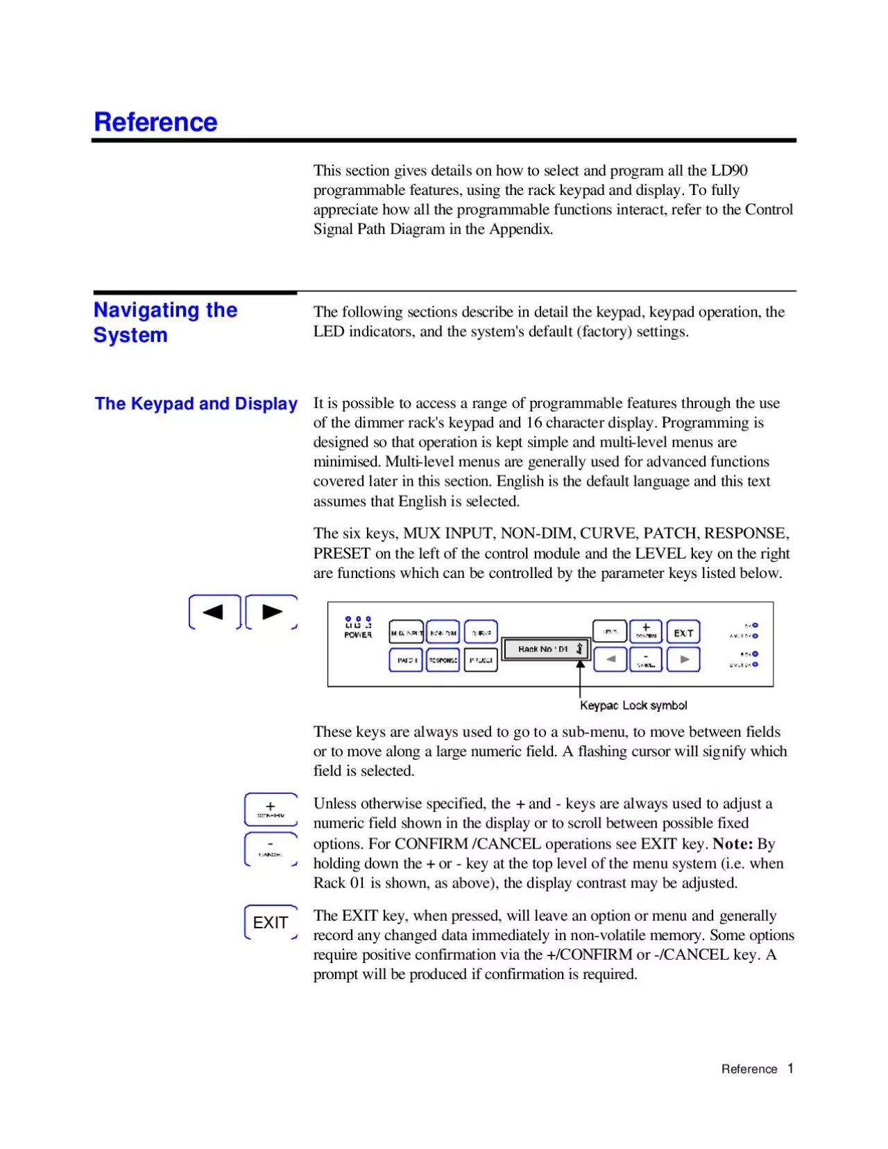
This section gives details on how to select and program all the LD90 programmable features using the rack keypad and display To fully appreciate how all the programmable functions interact refer to th ID: 881654

dimmer dimmers set mux dimmers dimmer mux set control preset number key reference operation level rack patch default input

Share:

Link:

Embed:

Download Presentation from below link

Download Pdf The PPT/PDF document "Reference 1 Reference" is the property of its rightful owner. Permission is granted to download and print the materials on this web site for personal, non-commercial use only, and to display it on your personal computer provided you do not modify the materials and that you retain all copyright notices contained in the materials. By downloading content from our website, you accept the terms of this agreement.


Presentation Transcript

1 Reference 1 Reference This section gi
Reference 1 Reference This section gives details on how to select and program all the LD90 programmable features, using the rack keypad and display. To fully appreciate how all the programmable functions interact, refer to the Control Signal Path Diagram in the Appendix. The following sections describe in detail the keypad, keypad operation, the LED indicators, and the system's default (factory) settings. It is possible to access a range of programmable features through the use of the dimmer rack's keypad and 16 character display. Programming is designed so that operation is kept simpl

2 e and multi-level menus are minimised. M
e and multi-level menus are minimised. Multi-level menus are generally used for advanced functions covered later in this section. English is the default language and this text assumes that English is selected. The six keys, MUX INPUT, NON-DIM, CURVE, PATCH, RESPONSE, PRESET on the left of the control module and the LEVEL key on the right are functions which can be controlled by the parameter keys listed below. These keys are always used to go to a sub-menu, to move between fields or to move along a large numeric field. A flashing cursor will signify which field is selected. Unless otherwise s

3 pecified, the + and - keys are always us
pecified, the + and - keys are always used to adjust a numeric field shown in the display or to scroll between possible fixed options. For CONFIRM /CANCEL operations see EXIT key. Note: By holding down the + or - key at the top level of the menu system (i.e. when Rack 01 is shown, as above), the display contrast may be adjusted. The EXIT key, when pressed, will leave an option or menu and generally record any changed data immediately in non-volatile memory. Some options require positive confirmation via the +/CONFIRM or -/CANCEL key. A prompt will be produced if confirmation is required. Navi

4 gating the System The Keypad and Displ
gating the System The Keypad and Display +X 2 The keypad has a lock facility, requiring the key combination MUX. INPUT and RESPONSE to be held down for 2-3 secs. to activate / deactivate it. When locked, a lock symbol is displayed as shown below. The lock will be automatically re-enabled after 10 minutes. When the rack is switched on, a number of self-tests are run and the system displays the following message for a few seconds It checks and shows the rack configuration and version of software, A1 in this case; and number of dimmers fitted to each phase (888 in this case). Other con

5 figurations are shown below. No POWER BL
figurations are shown below. No POWER BLOCKS fitted. 4 dimmers fitted to each phase (3 x 5kW usually). 8 dimmers fitted to each phase (3 x 2.5kW usually) 8 dimmers fitted to L1 and L2 phases, 4 dimmers fitted to L3. Any other configurations will display accordingly. The default display, shown left, appears as soon as this software check is complete. LD90 has 7 green LED indicators to indicate its status. LED's associated with MUX B are part of the optional MUX B processor. Phase Power present at Processor Unit Main processor is running. A flashing condition indicates that over temperature ha

6 s been detected in one or more Power Blo
s been detected in one or more Power Blocks. Optional multiplex receiver B processor fitted and running. Shows that valid multiplex signals are being received at the Mux A or Mux B input. Keypad Lock EXCB 3L2AHSPE 1 k:1 SEVE Power up Display 000444 888884 L1, L2, L3O.K.B OKMUX A OK / MUX B OK Reference 3 When first switched on from new, or when set to defaults, the following functions will be set to the following states: MUX INPUT A & B DMX 512 NON CURVE All dimmers = Square PATCH Start address of dimmer 01=0001 RESPONSE All dimmers = Medium PRESET Preset 0 = Should a mux failure occur

7 all dimmers will fade to blackout after
all dimmers will fade to blackout after a period of 10 seconds. LEVEL Dimmers take levels from control inputs (MUX, analogue etc). Note that every time the dimmer system is switched on, even if a LEVEL was set previously, it will always respond to the control inputs. System Default Settings 4 The following tree diagram gives an outline of the menu system. Generally the first line of each menu is the most commonly required function. Function Keys & Menu Levels Reference 5 The procedure illustrated below shows how to check all default settings. After unlocking the keypad pressing th

8 e appropriate keys as shown will step th
e appropriate keys as shown will step through each default in turn. The symbol indicates that there is another menu level available. Note that for menus that control ALL dimmers, a confirmation will be requested on EXIT. Pressing +/CONFIRM will ensure that all dimmers are set to the specified value. Pressing -/CANCEL will leave them as programmed. Ipu12k:1k:1Lalonlfel:lpualualdM001n1 se Checking Default (Factory) Settings 6 Protocols can be changed to any of the following options shown in the procedure below. The Input B parameters are not available unless the optional 2nd mux pro

9 cessor is fitted. EXCCCCCCC The C ke
cessor is fitted. EXCCCCCCC The C key may also be used to step through these options. The Mux Input Key Reference 7 This key allows dimmers to be assigned as "Non-Dims", i.e. they will remain at zero below the set threshold (%) and at full if above the threshold Basic Operation Example: Dimmer 05 to 50%, Dimmer 06 to 90%. (Max. setting) Nn1n5n5n50n50n6n6n60k:1k:1Xsdop50 dop90 D The Non-Dim Key 8 There are 3 dimmer curves available, these are supplied for compatibility purposes with other dimmers or applications. T.V. requirements generally use SQUARE whilst the S-curve allows m

10 atching with older dimmers. LINEAR is mo
atching with older dimmers. LINEAR is most suitable for theatre use. SQUARE is the default. The following graphs illustrate the relationship between input signal and output voltages for the different curves. Note: Separate curves apply to fluorescent fittings, these are selected automatically with the FLUORESCENT DIMMER SETUP in the SETUP menu. Basic Operation Example: Set ALL dimmers to LINEAR The Curve Key LD90 Dimmer Laws (shown with 230V nominal supply) Control Signal Level (%) RMS Output Voltage (V) 050100150200250010203040506070100 Reference 9 Example: Set Dimmer 05 to S- The

11 PATCH function allows you to allocate d
PATCH function allows you to allocate dimmer numbering according to your own requirements. · The Mux: Start option is the most basic facility, allowing you to patch all dimmers in the rack sequentially after the specified Start Number. · The Mux:Dimmer option allows you to assign each dimmer to a specified multiplex number. Note that D54 protocol has a maximum spread of 52 dimmers, starting at the Mux: Start number. · The Mux:Circuit option allows you to assign your own dimmer numbers or names independently of the Start Number or Dimmer patch. It is an important facility but only for use

12 with SWC or SV90. The facility allows yo
with SWC or SV90. The facility allows you to use your desk's channel numbering scheme, or even a geographic numbering scheme, (e.g. 100, 101, 102... 110, 111, 112 etc. when remotely controlling dimmers in a complete system. (See ADVANCED OPERATION for an example). The Patch Key 10 Basic Operation Example 1: On a 3 rack system where all POWER BLOCKS are 2.5kW dimmers (24 per rack) the third rack would normally start at dimmer number 49. To set this, follow the procedure below: Note: It is not recommended to alter PATCH with dimmers on, as patching operations will directly affect light output.

13 Reference 11 M001001041041049k:3a
Reference 11 M001001041041049k:3ank:3XXAHsssp3 ++ Note: The mux address will change as the dimmer number is changed showing the address that the dimmer is patched to. Remember that any changes to the patch will be seen on the lighting output immediately. 12 Example 2: Dimmers 1-2 are both to be assigned to mux number 100. When using the D54 protocol, you must set the Mux: Start Number to the lowest Mux address that you want to patch any dimmer to. When using the Mux:Patch facility, the software will not allow you to set any dimmer to respond to an address more than 52 higher than

14 this number. Mk:1k:1XAHCCsss ssss 1001
this number. Mk:1k:1XAHCCsss ssss 1001 1100 1001 2002 1001 2002 1101 2102 1101 2102 1100 2100 ++- Reference 13 Example 3: By utilising the Circuit feature on LD90 it is possible to give dimmers 5 character identification names or numbers, for instance Dimmer 5 is to be called 913. Giving dimmers Circuit numbers will prove useful when LD90 is used with the optional SWC Remote or the SV90 Programming Terminal which may be used to control significant numbers of dimmers. Note that the Circuit ID must be a 4 digit numeric value only to be used with the SWC Programmer, as the unit only has

15 numeric keys. Advanced Operation Exa
numeric keys. Advanced Operation Example: A 24 dimmer LD90 is being added to an existing installation of 16 Permus racks (dimmer capacity 384) driven by a Galaxy console. The total number of dimmers is 408, so exceeding the capacity of one D54 Mux link. The Galaxy's second mux output must be used, driving dimmers 385-768. However, there is no implicit number carried in the D54 Mux signal to tell the new dimmer rack that it is receiving 385-768. To the dimmers it appears as 1-384 again. 14 By setting the dimmer Circuit ID's to 385-408 and the start number to 1, the dimmer can be controll

16 ed both by the Galaxy and SWC Programmer
ed both by the Galaxy and SWC Programmer or SV90 as dimmers 385-408. The Circuit ID feature will allow us to do this as shown in the diagrams overleaf. The response speed of a dimmer is the rate at which it responds to an increase or decrease in its control level. Three speeds are available, MEDIUM, FAST and SLOW, corresponding to 100mS, 30mS and 300mS. SLOW is generally used for large lamp loads e.g. 5kW fittings such as QUARTZCOLOR POLLUX, whilst FAST is used for small lamp loads such as those used in a chase effect The Response Key Reference 15 16 Basic Operation Example: Set all d

17 immers to FAST Ronlonlldlk:1ank:1XXSPE
immers to FAST Ronlonlldlk:1ank:1XXSPE + The fast setting together with the accuracy of digital dimmers can cause very high inrush currents to flow. These may damage large lamp filaments and cause circuit breakers to trip. Only set dimmers to FAST if necessary for a particular effect. Advanced Operation Example: Set dimmer 8 to SLOW EXsp 8 SPE ++ Reference 17 There are 99 user programmable Presets. PRESET 0 is a non-recordable blackout state. It is possible to record your own preset states and assign any one of them as a 'backup' state that will fade in 10 seconds after the Mux.

18 signal has failed (the NoMux preset). Th
signal has failed (the NoMux preset). The dimmer always records total output into the selected PRESET. Any of the Presets may be called up and added to the dimmer output in a 'Highest Takes Precedence' (HTP) manner from the rack keypad, or, remotely by SWC or SV90. This is the PRESET VIEW facility. When selected, the preset will crossfade at the default time of 10s, or if using SWC or SV90, a recorded time, from any previously selected preset. Since PRESET VIEW operates on a Highest Takes Precedence (HTP) basis with other control inputs (e.g. the multiplexed signal from a lighting desk), if

19 a preset has been left 'on view' it wil
a preset has been left 'on view' it will not be possible to subsequently fade down the dimmers from the lighting desk. To avoid problems, always turn off the preset after use. Basic Operation Example: Record dimmer output into preset 1 1. Set up the desired lighting state first using any control means. 2. Follow the procedure as shown. 3. Repeat for any other Presets that are required. EX The Preset Key 18 Advanced Operation NoMux=0 is the default setting, causing a fade to blackout when the Mux signal from the control desk ceases. Setting NoMux to any of the Presets 199 causes the se

20 lected preset to be faded up instead. Se
lected preset to be faded up instead. Setting NoMux to HOLD (HLD) will allow the current lighting state to remain in the event of a Mux failure. This is useful as a safety feature in live performance situations. Setting NoMux to HOLD may cause problems if the dimmers are left on after the control desk is turned off. Many desks produce unwanted signals as the power fails, and once the desk is turned off, the dimmers are susceptible to noise pickup on the Mux Input. This can leave the dimmers unexpectedly ON. If you set NoMux to HOLD, make sure unattended dimmers are turned off. Example: Assign

21 preset 5 as the 'backup 'state Pf005k:
preset 5 as the 'backup 'state Pf005k:1k:1XSE +sp 5 Example: Set NoMux to HOLD Pf00Rk:1k:1 C s Reference 19 This function allows dimmers and loads to be tested directly from the keypad, regardless of the signals, Mux or otherwise that are being received from inputs. Either ALL or individual dimmers may be set to any % level. Note: Since this control overrides the control inputs, including the Presets, it is possible to completely disable any or all of the dimmers. This is not a safety switch off mechanism however. It is easy to forget to set the dimmers back to INPUT, giving ri

22 se to unexpected lack of control. Norm
se to unexpected lack of control. Normally this control is set to ALL=INPUT whereby all dimmers will be controlled by the Mux generated by a lighting console, analogue inputs and Presets. This control may also be used to set up states for recording into Presets in architectural situations where there is no conventional lighting desk available. The lighting console is overridden by this key but the MINIMUM DIMMER LEVEL and MAXIMUM VOLTAGE set in the RACK SETUP procedure still take overall precedence. This should be borne in mind when using the facility. Basic Operation Example: Set all dim

23 mers to 50% The Level Key 20 Advance
mers to 50% The Level Key 20 Advanced Operation Example: Dimmer numbers 5 and 8 are to set to 90% Selem:1pu:5pu:5pu:50:50:8pu:8pu:80k:1k:1X dounlappeadounl0ppeadounl0ppeapnobodmonencdtenps ++++ Sometimes, the software may produce an unexpected message, due to external or internal reasons. Each "Error" has a unique number and is logged internally in non-volatile memory. If a message should appear, then its number should be written down and referred to your Strand Lighting service agent or dealer. The message can be cleared by pressing EXIT. User Messages Reference 21 Referen