
Project Scientists Contributions from Hassan Oudrari and Government VIIRS Data Analysis Working Group NASA NOAAIPO Aerospace MITLincoln Wisconsin 37 members 20 NASA 13 Aerospace 4 MIT LL ID: 1024425
Download Presentation The PPT/PDF document "NPP/VIIRS: Status Jim Gleason, Jim Butle..." is the property of its rightful owner. Permission is granted to download and print the materials on this web site for personal, non-commercial use only, and to display it on your personal computer provided you do not modify the materials and that you retain all copyright notices contained in the materials. By downloading content from our website, you accept the terms of this agreement.


1. NPP/VIIRS: StatusJim Gleason, Jim Butler, N. Christina HsuProject ScientistsContributions from:Hassan Oudrari andGovernment VIIRS Data Analysis Working GroupNASA, NOAA/IPO, Aerospace, MIT/Lincoln, Wisconsin37 members, 20 NASA, 13 Aerospace, 4 MIT LL (29 East Coast, 6 West Coast, 2 Wisconsin) Launch Date: October 25, 2011
2. When we last met:VIIRS in Clean Room with NPPNo CrISVIIRS
3. Current Status:NPP Completed Environmental Testing
4. 4 NPP Status:VIIRS – Medium resolution Visible& Infra-red ImagerCrIS – Fourier Transform Spectrometer for IR Temperature and Moisture soundingATMS – Microwave sounding radiometerOMPS – Total Ozone Mapping and Ozone Profile measurements CERESVIIRSCrISATMSOMPS LimbOMPS NadirCERES Earth Radiation Budget measurementsCompleted Environmental Testing; Shock, Acoustics, Vibration, EMI/EMC, Thermal Vacuum
5. 5Visible Infrared Imaging Radiometer SuiteDescriptionPurpose: Global observations of land, ocean, & atmosphere parameters at high temporal resolution (~ daily)Predecessor Instruments: AVHRR, OLS, MODIS, SeaWiFSApproach: Multi-spectral scanning radiometer (22 bands between 0.4 µm and 12 µm) 12-bit quantizationSwath width: 3000 kmStatusCompleted comprehensive performance monitoring testing during TV testing.Performance is nominal Preparing for Launch
6. Status of VIIRS F1 Performance TestingVIIRS F1 testing program completed all planned testing phases, and has provided test data to support 141 sensor performance requirements:NASA team has completed extensive test data analysis and VIIRS F1 performance requirement verification: VIIRS testing program was comprehensive and provided necessary test data to characterize VIIRS performance, and to establish a good baseline for on-orbit operations..All performance waivers have been evaluated by NGST and reviewed by NASA teamMost waivers have small to negligible EDR performance impactsAlgorithm revisions and/or changes to Cal/Val tasks were added to support waivers
7. VIIRS F1 Reflective Bands: Radiometric PerformanceMeets all Requirements for:Signal to Noise Ratio, Dynamic Range, Linearity, Uncertainty, Stability and PolarizationMinor Variances for: Gain Transition: Gain transition points are well characterized(VIIRS has dual gain bands) Uniformity: Potential for striping, Plan for post-launch fix if needed
8. VIIRS F1 Emissive Bands:Radiometric PerformanceMeets all Requirements for:NEdT, Dynamic Range, Gain Transition, Linearity, Uniformity, Absolute Radiometric Difference, and Stability
9. VIIRS F1 Spatial PerformanceMeets Requirements for or only minor non-compliances: Line Spread Function: Scan and Track DFOV Scan and Track MTF Scan and Track HSR Band-to-Band RegistrationPixel growth to “1.5 km x 1.5 km” at to the edge of scan
10. VIIRS F1 Spectral PerformanceLargely Meets all Requirements for:Spectral Band Center, Spectral Bandwidth, Extended Bandwidth Minor non-compliances are well characterized. No impact expected.Non-Compliances for Integrated Out-of-Band (OOB) ResponseMany bands did not meant the IOOB requirements, but low impactMultiple spectral testing provided a reliable F1 IOOB characterizationSpectral Band-to-Band CrosstalkVIIRS did not meet crosstalk requirements, which are much more strict than heritage values (e.g. MODIS)Optical cross-talk issue is well known (IFA defects), and intensively studied by both contractor and Government teams, using characterization data from testing performed at IFA and sensor levels.Impact analysis has shown Ocean and Aerosol EDRs products sensitive to this crosstalk effect. A mitigation plan was established for on-orbit operations in the case of these 2 EDRs.
11. Government Team’s VIIRS RSRsReflective and Emissive BandsVIIRS M1 BandVIIRS LWIR Bands
12. Testing SummaryVIIRS F1 test program is complete and has provided good test data to assess sensor performance.All F1 sensor performances has been verified, and non-compliances are expected to have minor effect on NASA science.Effort by both Government and Contractor finalized sensor performance to generate VIIRS F1 on-orbit LUTs for SDR algorithm.VIIRS measured performance, supported by planned calibration and validation activities is expected to meet NASA science objectives
13. ManeuversAll VIIRS maneuvers have been approved by NPP ProjectLunar Rolls and Pitch-up for deep space view and Yaws for diffuser characterizationManeuvers will be done during Intensive Cal/ValWorking with NOAA and JPSS to ensure maneuvers part of regular operating baseline
14. JPSSJPSS Transition is ongoingFY10 & FY11 (& FY12??) budgets are a challengeGovernment taking responsibility for IDPS Data Product PerformanceNOAA NESDIS STAR providing leadership for VIIRS data productsChangyong Cao for VIIRS SDRIvan Csiszar for VIIRS EDRs Existing Gov’t funded cal/val activities are continuing.
15. QuestionsLaunch Date: October 25, 2011
16. 16Maneuver #1 – Roll -25 degrees Roll Maneuver (-X) - up to –25 degrees on the dark side of the orbit, and maintaining the offset for up to 5 minutes. Spacecraft baseline requirement : YESScience Rationale / BenefitMeets needs of VIIRS Lunar Roll maneuver #8ADCS / Thermal AssessmentReference : SER 3257-THR248 (Thermal model V72)SRS analysis accesses compliance to all thermal requirements of all spacecraft components and instrument interfaces throughout these maneuvers for Nominal Operation Science Mode (instruments powered on with doors open) as well as SRS Commissioning Maneuver Checkout (instruments powered off with doors closed). Eight individual hot and cold cases for bounding beta angles 12º and 34º were run; four in each mode.SummaryAs part of spacecraft ADCS commissioning, BATC will demonstrate this maneuverSRS Compliance if performed in eclipse, S/C –Y side toward earthOrientation modeled and all thermal parameters within allowable limits based on analysisRoll -25º NominalNominal
17. 17Maneuver #2 – Yaw +/-25 degrees Yaw Maneuver (+/-Z) : yaw offset pointing up to 25 degrees, and maintaining the offset for up to 15 minutes at any point in the orbit.Spacecraft baseline requirement : YES-25º Yaw, Sun Side +25º Yaw, Sun Side -25º Yaw, Eclipse Side +25º Yaw, Eclipse SideScience Rationale / BenefitMeets needs of VIIRS Solar Diffuser Cal maneuver #9Meets needs of CERES Sunrise Solar Calibration maneuver #9 and Sunset Solar Calibration maneuver #10ADCS / Thermal AssessmentReference : SER 3257-THR248 (Thermal model V72)SRS analysis accesses compliance to all thermal requirements of all spacecraft components and instrument interfaces throughout these maneuvers for Nominal Operation Science Mode (instruments powered on with doors open) as well as SRS Commissioning Maneuver Checkout (instruments powered off with doors closed). Thirty-two individual subsolar and eclipse, hot and cold cases for beta angles 12º & 34º, at +25º and -25º, were run. Sixteen cases for each modeSummaryAs part of spacecraft ADCS commissioning, BATC will demonstrate this maneuverSRS Compliance to demonstrate yaw out to +25 deg, occurs in eclipse and daylight SRS Compliance to demonstrate yaw out to -25 deg, occurs in eclipse and daylightOrientation modeled and all thermal parameters within allowable limits based on analysis
18. 18Maneuver #3 – Pitch Over ManeuverPitch Over - +Y slew in the opposite direction of the orbital pitch rate over 1/3 of the orbit, starting at terminator crossing from the Science Mode attitude, at the lowest constant rate that will return the Spacecraft to nominal pointing at the end of the slewSpacecraft baseline requirement : YES Science Rationale / BenefitMeets VIIRS, ATMS and CERES needs for view of deep space maneuver #6ADCS / Thermal AssessmentReference : SER 3257-THR248 (Thermal model V72)SRS analysis accesses compliance to all thermal requirements of all spacecraft components and instrument interfaces throughout these maneuvers for Nominal Operation Science Mode (instruments powered on with doors open) as well as SRS Commissioning Maneuver Checkout (instruments powered off with doors closed). Eight individual hot and cold cases for beta angles 12º & 34º were run. Four cases for each modeSummaryAs part of spacecraft ADCS commissioning, BATC will demonstrate this maneuverSRS Compliance to demonstrate one back flip in eclipse,Orientation modeled and all thermal parameters within allowable limits based on analysisNominal, Dusk Terminator Pitch 90º Pitch 270º Nominal, Dawn Terminator Pitch 180º
19. 19Maneuver #6 – Pitch ManeuverVIIRS, CERES, ATMS Pitch Maneuver (+Y) : slew in the opposite direction of the orbital pitch rate over 1/3 of the orbit, starting at terminator crossing from the Science Mode attitude, at the lowest constant rate that will return the Spacecraft to nominal pointing at the end of the slewSpacecraft baseline requirement : YesScience Rationale / BenefitFrequency/Dwell : Twice separate by 1 orbit in the absence of the moonHeritage : NOAA 14 at EOL; Terra after 2 yearsScience Improvement : VIIRS 0.5-1% Asymmetry correction ATMS 1-3% Scan Bias Correction due to side lobe contributions based on both ATMS rolls (#4/#5) and the pitch over maneuver (#6)CERES Reduces Offset uncertainty from 50 to 12 % (4:1)ADCS / Thermal AssessmentADCS Reference: SER 3257-ACS339Thermal Reference : SER 3257-THR250All bus components and instrument interfaces are compliant and within their flight allowable limits throughout each of calibration maneuvers with instruments powered on and doors open.Prior to the pitch maneuver, the spacecraft remained in its nominal science mode orbit. Four individual hot and cold cases for beta angles 12º & 34º were run, where instruments are powered on with doors open. SummaryThis maneuver was accepted but will be limited to only one pitch maneuver. It will be performed between L+3 and L+6 months post launch. A revised thermal analysis is a prerequisite using on orbit thermal data.Extended view of deep space for the calibration of potential scan asymmetry. Same as VIIRS and CERES Pitch maneuvers, hence only one consolidated maneuver is needed, but simulated twice, separated by one orbit (as required for ATMS).Risk of VIIRS / CrIS cryo temperatures rise above set points or reverse bias on VIIRS cooler stages for low beta angles. Possible loss of emissive bandNominal, Dusk Terminator Pitch 90º Pitch 270º Nominal, Dawn Terminator Pitch 180º
20. VIIRS Performance Evaluation based on Spacecraft TVAC TestingNASA/NICST team provided an independent verification of the VIIRS performance measured during NPP TVAC testing.NASA/NICST team received and processed all four VIIRS CPT test data, from Cold-1, Hot-1, Cold-4 and Hot-4 plateaus. CPT testing included:NASA/NICST team released about seventeen (17) reports and summaries over 43 days of VIIRS TVAC testing, describing preliminary results of the test data analysis.NASA/NICST verified that VIIRS data collected and analyzed are of good quality and sufficient to verify sensor performance.NASA/NICST team summaries are in agreement with the contractor’s findings, that the sensor performance is as expected, and no specific concern or issue was identifiedVIIRS Performance Evaluation based on Spacecraft TVAC Testing PerformanceDescriptionRiskGain and SNRFPI source is used to illuminate VIIRS sensor inside the TVAC chamber at Ball. Gain values derived for VIIRS bands are within 10% of sensor level gains.SNR meet specification, but lower than sensor level testing (Source issue).LowOBC Warm-up/Cool-downOBC operations meet spec for range and uniformity. Gain within 1.2% of sensor level testingLowElectronics Self-TestIn agreement with sensor level testingLowNoiseIn agreement with sensor level testingLowSDSM CheckoutSDSM functionality verified (mirro rotating normally)LowTrending of gain and noiseNo anomalies observed during the self compatibility testingLow
21. Lower-left = # of Det out of Spec, upper-right = test results. Worst BBR meets Spec in Agg1 zone (+/-56.28,+/-44.86 deg) with bow-tie deletion, except 1 det pair M13 vs M9. BBR in Agg2 (+/-44.86, +/-31.72) and Agg3 (-31.72, +31.72 Deg) is better.The root cause of the out of Spec BBR pair (M13 vs M9) is primarily due to effective focal length (EFL) to scan rate mismatch. Yellow cells: BBR with <= 5% margin in the ground tests which may be out-of-Spec when in orbit with effects of S/C jitter etc.Lin et. al., 20091201Science Data Segment / NICSE 21VIIRS F1 Band-to-Band Registration PerformanceWorst BBR @ Nominal Perf Plateau
22. VIIRS F1 Polarization PerformanceAll Bands Meet Polarization Requirements
23. VIIRS Radiometric Requirements: Emissive Bands TABLE 17: Absolute radiometric calibration uncertainty of spectral radiance for moderate resolution emissive bandsAll Reflective Bands Meet Radiometric Requirements With Margins
24. VIIRS F1 Performance StatusBased on sensor level TV testingVIIRS F1 test program is complete and has provided good test data to assess sensor performance.Sensor performance exceeds requirements in most cases, and non compliances were addressed in waiver packages and impact assessmentsNASA performance assessments are beginning of life (BOL). Modeling of EOL performances are available in Raytheon Performance Verification Reports (PVRs). Government team finalized VIIRS F1 Performance assessments to generate on-orbit LUTs for SDR algorithm
25. VIIRS F1 Bands and SNR/NEDTAll Bands Meet SNR Requirements With Margin
26. 26TABLE 5. VIIRS Spectral band optical requirements[1] The values given under "OOB Integration Limits" are the specified limits on the 1% relative response points.[2] The OOB integration limits will be the 1% response points determined during sensor characterization.
27. 27Spectral radiance (Lmin and Lmax) has units of watt m-2 sr-1 mm-1.TABLE 12. Dynamic range requirements for VIIRS Sensor reflective bands
28. 28TABLE 13. Dynamic range requirements VIIRS Sensor emissive bands
29. 29TABLE 14: Sensitivity requirements for VIIRS Sensor reflective bandsNotes:The units of spectral radiance for Ltyp are watt m-2 sr-1 mm-1.The SNR column shows the minimum required (worst-case) SNR that applies at the end-of-scan.
30. 30TABLE 15: Sensitivity requirements for VIIRS Sensor emissive bands
31. 31Table # 17/18: Emissive Bands RadiometricCalibration Accuracy RequirementsEquivalent or Better Performance Was Achieved on MODIS
32. VIIRS F1 Spectral PerformanceMeets all Requirements for:Spectral Band Center, Spectral Bandwidth, Extended Bandwidth Significant Non-Compliance for: Integrated Out-of-Band ResponseNotes: Smaller non-compliances for emissive bands Well characterized Difficult to separate from Cross-talk effectsBandCenter Wavelength (nm)Bandwidth (nm)RequirementMaximum Integrated OOB Response (%)MeasuredMaximum Integrated OOB Response (%)M1412201.0 3.7M3488200.7 1.1M4555200.74.3M5672200.73.2M6746150.81.8
33. 333-Mirror AnastigmatAll reflectiveRotating telescopeVIIRS Incorporates Modular Sensor ApproachCryoradiator4-Mirror AnastigmatAll ReflectiveAft Optics ImagerBlackbodySolar DiffuserHalf-angle MirrorSeparately Mounted Electronics ModuleSolar DiffuserStability MonitorFPIEOMM configurationCold FPADewar AssemblyRTMA
34. Radiative Cooler/Earth Shield VIIRS F1 Sensor Block DiagramSolarDiffuserBlackbodySunSpaceView EarthRotatingTelescopeAssembly FPADewarFocal PlaneElectronicsReadout &A/DConversionFormatterBufferCompressionCCSDS1394 Data Power, Command,Control, TelemetryLWIR (4)SWIR/MWIR (8)Beam-splitterSDSMBeam-splitterBeam-splitterImagerDNB/VNIR (10 bands)GroundSupport andSystem TestEquipmentDNB - Day/Night “Band”VisNIR - Visible/Near IRSWIR - Short Wave IRMWIR - Mid Wave IRLWIR - Long Wave IRHAM - Half Angle Mirror SDSM - Solar Diffuser Stability MonitorHAMMoonImage provided courtesy of NASA GSFC34
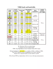
35. 35VIIRS Bands and ProductsDual gain bandVIIRS 22 Bands:16 M-Band, 5 I-Band and 1 DNBVIIRS 24 EDRsLand, Ocean, Cloud, Snow* Product is a Key Performance Parameter (KPP)Similar MODIS bands are shown for comparison
36. 36VIIRS Spectral, Spatial, & Radiometric Attributes
37. VIIRS F1 Sensor Gov’t ActivitiesVIIRS F1 testing program is complete and has provided test data to support 141 performance requirementsNASA team has completed extensive analysis of VIIRS test dataSupport of sensor test data analysis, and requirement verificationRelease more than 130 reports and memos just Instrument TV phaseSupport to Waiver evaluation, including SDR/EDR impact assessmentNICST Data Analysis Satellite TV Summaries:NICST team released five (5) Summaries on Friday April 22nd in support of the SC TVAC CTB meeting held on April 23rd. These VIIRS summaries represent NICST’s assessments of the overall VIIRS SC TVAC performance testing, NICST is planning to develop detailed reports for VIIRS performance assessment based on SC TVAC testing. NICST team summaries did not identify any specific concern or issue, and have shown that all VIIRS data collected and analyzed are of good quality and sufficient to verify that sensor performance is as expected.
38. 38Team Coordination