
Results of FEA amp Structural analysis Final model Conclusion ETCS Unit Motor Spec Design method of an ultrahigh speed PM MotorGenerator for ElectricTurbo Compounding System Objectives ID: 1021075
Download Presentation The PPT/PDF document "Results of FEA & Structural analysi..." is the property of its rightful owner. Permission is granted to download and print the materials on this web site for personal, non-commercial use only, and to display it on your personal computer provided you do not modify the materials and that you retain all copyright notices contained in the materials. By downloading content from our website, you accept the terms of this agreement.


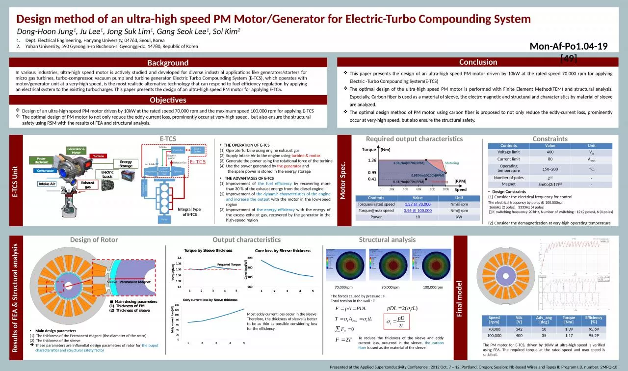
1. Results of FEA & Structural analysisResults of FEA & Structural analysisFinal model ConclusionE-TCS UnitMotor Spec.Design method of an ultra-high speed PM Motor/Generator for Electric-Turbo Compounding SystemObjectivesBackgroundDong-Hoon Jung1, Ju Lee1, Jong Suk Lim1, Gang Seok Lee1, Sol Kim2 Dept. Electrical Engineering, Hanyang University, 04763, Seoul, KoreaYuhan University, 590 Gyeongin-ro Bucheon-si Gyeonggi-do, 14780, Republic of KoreaPresented at the Applied Superconductivity Conference , 2012 Oct. 7 – 12, Portland, Oregon; Session: Nb-based Wires and Tapes II; Program I.D. number: 2MPQ-10In various industries, ultra-high speed motor is actively studied and developed for diverse industrial applications like generators/starters for micro gas turbines, turbo-compressor, vacuum pump and turbine generator. Electric Turbo Compounding System (E-TCS), which operates with motor/generator unit at a very-high speed, is the most realistic alternative technology that can respond to fuel efficiency regulation by applying an electrical system to the existing turbocharger. This paper presents the design of an ultra-high speed PM motor for applying E-TCS. Required output characteristicsE-TCSTHE OPERATION OF E-TCSOperate Turbine using engine exhaust gasSupply Intake Air to the engine using turbine & motorGenerate the power using the rotational force of the turbineUse the power generated by the generator and the spare power is stored in the energy storage 70,000rpmThis paper presents the design of an ultra-high speed PM motor driven by 10kW at the rated speed 70,000 rpm for applying Electric -Turbo Compounding System(E-TCS)The optimal design of the ultra-high speed PM motor is performed with Finite Element Method(FEM) and structural analysis. Especially, Carbon fiber is used as a material of sleeve, the electromagnetic and structural and characteristics by material of sleeve are analyzed.The optimal design method of PM motor, using carbon fiber is proposed to not only reduce the eddy-current loss, prominently occur at very-high speed, but also ensure the structural safety.Design of an ultra-high speed PM motor driven by 10kW at the rated speed 70,000 rpm and the maximum speed 100,000 rpm for applying E-TCSThe optimal design of PM motor to not only reduce the eddy-current loss, prominently occur at very-high speed, but also ensure the structural safety using RSM with the results of FEA and structural analysis.Design of RotorMain design parametersThe thickness of the Permanent magnet (the diameter of the rotor)The thickness of the sleeveThese parameters are influential design parameters of rotor for the ouput characteristics and structural safety factor THE ADVANTAGES OF E-TCSImprovement of the fuel efficiency by recovering more than 30 % of the exhaust energy from the diesel engineImprovement of the dynamic characteristics of the engine and increase the output with the motor in the low-speed regionImprovement of the energy efficiency with the energy of the excess exhaust gas, recovered by the generator in the high-speed regionIntegral type of E-TCSConstraintsContentsValueUnitTorque@rated speed1.37 @ 70,000Nm@rpmTorque@max speed0.96 @ 100,000Nm@rpmPower10kWContentsValueUnitVoltage limit400VdcCurrent limit80ApeakOperating temperature150~200°CNumber of poles2(1)-MagnetSmCo(2:17)(2)-Design Constraints Consider the electrical frequency for controlConsider the demagnetization at very-high operating temperature The electrical frequency by poles @ 100,000rpm 1666Hz (2 poles), 3333Hz (4 poles) if, switching frequency 20 kHz, Number of switching : 12 (2 poles), 6 (4 poles)Output characteristicsMost eddy current loss occur in the sleeveTherefore, the thickness of sleeve is better to be as thin as possible considering loss for the efficiency.Structural analysis90,000rpm100,000rpmThe forces caused by pressure : FTotal tension in the wall : T.To reduce the thickness of the sleeve and eddy current loss, occurred in the sleeve, the carbon fiber is used as the material of the sleeveSpeed[rpm]Vdc[V]Adv_ang[deg]Torque[Nm]Efficiency[%]70,000342101.3995.69100,000400351.1795.29The PM motor for E-TCS, driven by 10kW at ultra-high speed is verified using FEA. The required torque at the rated speed and max speed is satisfied.Mon-Af-Po1.04-19 [49]