
ticomaaj 4Q 2008 Amplifiers Op Amps Input impedance matching with fully differential amplifiers Introduction Impedance matching is widely used in the transmission of signals in many end applica tions across the industrial communications video medi ca ID: 22792
Download Pdf The PPT/PDF document "Analog Applications Journal Texas Instru..." is the property of its rightful owner. Permission is granted to download and print the materials on this web site for personal, non-commercial use only, and to display it on your personal computer provided you do not modify the materials and that you retain all copyright notices contained in the materials. By downloading content from our website, you accept the terms of this agreement.


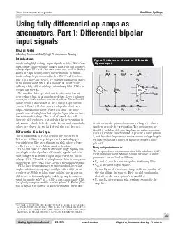
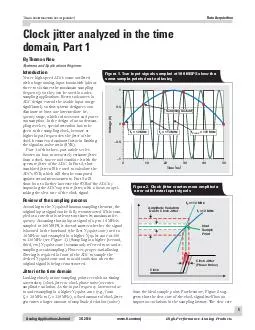
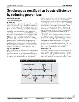
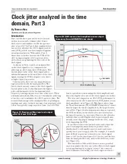

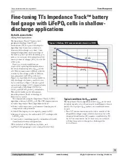

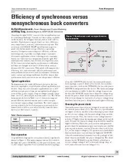
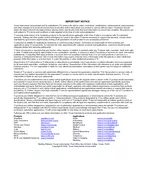
Analog Applications JournalTexas Instruments Incorporated High-Performance Analog Productswww.ti.com/aaj4Q 2008Amplifiers: Op AmpsInput impedance matching with fully differential amplifiersImpedance matching is widely used in the transmission of signals in many end applications across the industrial, communications, video, medical, test, measurement, and military markets. Impedance matching is important to reduce reflections and preserve signal integrity. Proper termination results in greater signal integrity with higher throughput of data and fewer errors. Different schemes have been employed; source termination, load termination, and double termination are the most commonly used. Double termination is generally recognized as the best method to reduce reflections, while source and load termination have the advantage of increased signal swing. With source and load termination, either the source or the load (not both) is terminated with the characteristic impedance of the transmission line. With double termination, both the TerminationS–Transmission ++––FDA Figure 1. FDA with differential source Texas Instruments Incorporated Analog Applications Journal 4Q 2008www.ti.com/aajHigh-Performance Analog ProductsAmplifiers: Op AmpsDue to this, we will first look at the input impedance in the differential case and then use that as a starting point to consider the single-ended case.The fundamentals of FDA operation are presented in Reference 1. Please refer to it for voltage definitions, gain equations, derivations, and terminology.A differential drive and termination into an FDA is shown in Figure 1. An FDA works using negative feedback around the main loop of the amplifier, which tends to drive the error voltage across the input terminals, V and V, to zero, depending on the loop gain.For analysis, it is convenient to assume that the FDA is an ideal amplifier with no offset and infinite gain. Looking at the input of the amplifier differentially and using the virtual-short concept (Figure 2) from an inverting-amplifier topology, we can express the input impedance as Z = || 2RFor an example of how to select the value of R, let’s look at a differential source driving a twisted pair to the FDA. Z = 100 is common for twisted-pair cables. For double termination, we want the source to provide R = 50 on each side for 100- differential output impedance, and we want the input of the FDA to present a 100- differential load. If R = 402 , we then need R to be 114.2 ; so we select the nearest standard value, 115 , for RThe gain of the circuit from the differential source is VVRRRRRRRSIGTTGTGSFG||||.222 If we assume that the input impedance matches the source impedance, then VVRRSIGTFG12. It is standard practice to take the gain from the terminated input, in which case VVRRINTFG. It is recommended that R be limited to a range of values for best performance. A resistance value that is too high will add excess noise and possibly interact with parasitic board capacitance to reduce the bandwidth of the amplifier; a value that is too low will load the output, causing increased distortion. Therefore, we need to pick a range of desired values for R and calculate R for the desired gain. For example, the THS4509 performs best with R in the range of 300 to 500 . So, depending on the gain we want from the FDA, there will come a point where 2R equals the required termination of the transmission line. In this case, no R resistor is required.In design, the target gain and Z are set by the system design. We select the value of R first, then calculate Rand R to match the gain and make Z = Z. This is easily done by setting up the equations in a spreadsheet. To see an example Excel worksheet, click on the Attachments tab or icon on the left side of the Adobe Reader window. OpenthefileFDA_Input_Impedance.xls,thenselecttheDifferential Input worksheet tab.SPICE simulation is a great way to validate the design. To see a TINA-TI simulation circuit of the example just given, click on the Attachments tab or icon on the left side of the Adobe Reader window. If you have the TINA-TI software installed, you can open the file FDA_Diff_Input_Impedance.TSC to view the circuit example. To download and install the free TINA-TI software, visit www.ti.com/tina-ti and click the Download button.There are numerous ways to find the input impedance in SPICE, but from the simulation waveforms shown in Figure 3, we see the expected input and output voltages for double termination with equal impedances. ()r+,-. Figure 2. Balanced input impedance GTIN Pâ( )T.+,- )/01+,- Figure 3. TINA-TI simulation of FDA waveforms with differential input impedance Texas Instruments Incorporated Analog Applications Journal High-Performance Analog Productswww.ti.com/aaj4Q 2008Amplifiers: Op AmpsIn Figure 4, the differential source circuit shown in Figure 1 is modified for a single-ended, DC-coupled source. To keep balance in the circuit, the source is converted to a single-ended source referenced to V; R is split into two resistors of equal value with the center point tied to ground; and the negative input is tied to V via RAnother scenario is when the source is an RF, IF, or CATV-type class-A amplifier that is designed with intrinsic output impedance. With this type of amplifier, AC coupling of the outputs is usually required via a DC-blocking capacitor to avoid disturbing the DC bias point of the amplifier. In this case, R on the positive side and R = R + R || Ron the negative side (where R is the output impedance of the RF/IF/CATV amplifier) should be tied to ground via a DC-blocking capacitor of the same size. This is shown in Figure 5. Note that in this configuration the FDA will self-bias input and output pins to the common-mode voltage set by the VIn actual implementation, the source may be DC-coupled (Figure 4) and have a common-mode reference that is not ground. In this case, care must be taken to tie R to the same common reference for balance. Also note that DC current will flow in R when tied to ground. When a source is DC-coupled with a ground-referenced source, Rand R on the negative side should be tied to ground.The last scenario makes the circuit analysis easier and will provide the solution for the other scenarios as well. Single-EndedAdded forBalance Gain-SettingResistors Z0 TransmissionTermination OUT– ++––FDA Figure 4. FDA with single-ended source Z0 Transmission S–RF/IF/CATV R=R+RREQGTS Figure 5. FDA with AC-coupled RF/IF/CATV amplifier input Texas Instruments Incorporated Analog Applications Journal 4Q 2008www.ti.com/aajHigh-Performance Analog ProductsAmplifiers: Op AmpsFigure 6 shows the case where the source is ground-referenced and R and R are combined with R into one resistor of equivalent value, R = R + R || R, which is tied to ground. We will base the analysis of the input impedance on this circuit.With single-ended input, only one side of the FDA is actively driven, and the other side is grounded (or tied to some reference as discussed earlier). With this scenario, the input pins of the amplifier are not fixed at a DC voltage but will have an AC component. So even though the error voltage across the inputs is driven to zero by the action of the amplifier, we can no longer use the virtual-short concept to derive the input impedance. Instead we must use an alternate, more complex method.The first step in analyzing the circuit is to break it along the center vertical axis into positive and negative input sides. Then the positive side is converted to its Thevenin equivalent so the circuit can be analyzed and a solution can be developed. Finally, the components on the negative side are balanced to make sure the amplifier gives balanced output. In the positive side of the circuit shown in Figure 7, |||| The Thevenin equivalent of the positive side is shown in Figure 8. In this circuit, IVVRRININTFG. We can treat V as a summing node, or solve the node equation to get VVRRRRRVRRRRRRINSIGTSTGFTSTGFST||||. At this point we make use of Equation 12 for output voltage from page 10 of Reference 1, with simplification and some slight changes in nomenclature. In the analysis we need to find V in relation to V, so will be used here in place of for the feedback factor in the Thevenin equivalent of the positive side. For the feedback factor of the negative side, will be used in place of . To clarify, the different terms that arise for the feedback factors are artifacts of the analysis, and in reality the circuit will have balanced feedback factors as long as R = R + R || RLet’s also zero out V because it is a DC level, and zero out V– because we grounded the input to the negative side of the amplifier.With these changes in nomenclature, and substituting the Thevenin equivalent shown earlier, we can derive the Z0 Transmission VS+VS–RFRFRGRSRTVOUT–VSIGVOUT+VOCMVIN ++––FDA EQG Figure 6. FDA with DC-coupled, single-ended source referenced to ground RFRGRTRSVOUT–VPVINIINZINZAVSIGI= 0P Figure 7. Positive side of FDA circuit RRST I= Figure 8. Thevenin equivalent of positive side VRR+RSIGTST equation for only the amplifier’s AC or signal response to , which we will call V VVRRRTSIGTST(),AC only1 (7)where RRRRRRRRRRGFGGSTFGST, and ||||. Texas Instruments Incorporated Analog Applications Journal High-Performance Analog Productswww.ti.com/aaj4Q 2008Amplifiers: Op AmpsWith a significant amount of algebra and substitution, we solve for Z and then use Equation 4 to find Z ZRRAGF1 The gain from the terminated input to the differential output, assuming the circuit is balanced, is VVRRRRRRRTDifferentialINFGSTTST()||.2 The output DC common mode is set by the input to VIt would be useful to have a closed-form equation to solve for R to satisfy both Equations 8 and 9, but none but sometimes that fails to find a solution. A more practical approach is to modify the equations and solve using Equations 10 and 11. 111212200RZGFGFGFRZGFTF, where Z is the desired termination, G is the target gain from terminated input to output, and F is a factor less than 1 that depends on the gain and value of R. The result is fed into Equation 11 to solve for R RRRGZRZRGTFTT200|| In design, the target gain and Z are set by the system design; and, as noted earlier, it is recommended that R be limited to a range of values for best performance. So we select the value of R first and then try values for F until Z = Z. This is easily done by setting up the equations in a spreadsheet that can simultaneously calculate with incremental values, and then selecting the appropriate values. To see an example Excel worksheet, click on the Attachments tab or icon on the left side of window.Input_Impedance.xls, then select the Single-Ended Input worksheet tab.For an example of how to select the value of Rlet’s look at a single-ended source driving a coax to the FDA with Z = 50 . For double termination, we want the source to provide R = 50- output impedance, and we want the input of the FDA to present a 50- single-ended load. Assuming that we want a gain of 1 from the terminated input and that R = 402 , we can use the spreadsheet to calculate the nearest standard values for R = 392 = 54.9 , and R = 422 , which gives us Z = and a gain of 1.006 V/V.Again we use SPICE simulation to validate the design. To see a TINA-TI simulation circuit of the example just given, click on the Attachments tab or icon on the left side of the Adobe Reader window. If you have the TINA-TI software installed, you can open the file FDA_Single_Ended_Input_Impedance.TSC to view the circuit example. To download and install the free TINA-TI software, visit www.ti.com/tina-ti and click the Download button.There are numerous ways to find the input impedance in SPICE, but from the simulation waveforms shown in Figure 9, we see the expected input and output voltages for double termination with equal impedances.For more information related to this article, you can download an Acrobat Reader file at www-s.ti.com/sc/techlit/ and replace “” with the TI Lit. # for the materials listed below.Document TitleTI Lit. #Jim Karki, “Fully Differential Amplifiers,” Application ReportRelated Web sitesamplifier.ti.comwww.ti.com/tina-ti GTIN Pâ( )T ),-./01 Figure 9. TINA-TI simulation of FDA waveforms with single-ended input impedance IMPORTANT NOTICE Texas Instruments Incorporated and its subsidiaries (TI) reserve the right to make corrections, modifications, enhancements, improvements, and other changes to its products and services at any time and to discontinue any product or service without notice. Customers should obtain the latest relevant information before placing orders and should verify that such information is current and complete. All products are sold subject to TIs terms and conditions of sale supplied at the time of order acknowledgment. TI warrants performance of its hardware products to the specifications applicable at the time of sale in accordance with TI's standard warranty. Testing and other quality control techniques are used to the extent TI deems necessary to support this warranty. Except TI Worldwide Technical Support PageTI Semiconductor KnowledgeBase Home PageMexicoEurope, Middle East, and Africa The European Free Call (Toll Free) number is not active in all countries. If you have technical difficulty calling the free call number, www.tij.co.jp/pi Toll-Free Number Taiwan © 2008 Texas Instruments IncorporatedTINA-TI is a trademark of Texas Instruments. Adobe and Reader are registered trademarks of Adobe Systems Incorporated. Excel is a registered trademark of Microsoft Corporation. ZigBee is a registered trademark of the ZigBee Alliance. All other trademarks are the property Safe Harbor Statement: This publication may contain forward-looking statements that involve a number of risks and uncertainties. These “forward-looking statements” are intended to qualify for the safe harbor from liability established by the Private Securities Litigation Reform Act of 1995. These forward-looking statements generally can be identified by phrases such as TI or its management “believes,” “expects,” “anticipates,” “foresees,” “forecasts,” “estimates” or other words or phrases of similar import. Similarly, such statements herein that describe the company's products, business strategy, outlook, objectives, plans, intentions or goals also are forward-looking statements. All such forward-looking statements are subject to certain risks and uncertainties that could cause actual results to differ materially from those in forward-looking statements. Please refer to TI's most recent Form 10-K for more information on the risks and uncertainties that could materially affect future results of operations. We disclaim any intention or obligation to update any forward-looking statements as a result of developments occurring after the date SLYT310 NOTICEInstrumentsIncorporatedanditssubsidiaries(TI)reservetherighttomakecorrections,modifications,enhancements,improvements,andotherchangestoitsproductsandservicesatanytimeandtodiscontinueanyproductorservicewithoutnotice.Customersshouldobtainthelatestrelevantinformationbeforeplacingordersandshouldverifythatsuchinformationiscurrentandcomplete.AllproductsaresoldsubjecttoTIstermsandconditionsofsalesuppliedatthetimeoforderacknowledgment.TIwarrantsperformanceofitshardwareproductstothespecificationsapplicableatthetimeofsaleinaccordancewithTIsstandardwarranty.TestingandotherqualitycontroltechniquesareusedtotheextentTIdeemsnecessarytosupportthiswarranty.Exceptwheremandatedbygovernmentrequirements,testingofallparametersofeachproductisnotnecessarilyperformed.TIassumesnoliabilityforapplicationsassistanceorcustomerproductdesign.CustomersareresponsiblefortheirproductsandapplicationsusingTIcomponents.Tominimizetherisksassociatedwithcustomerproductsandapplications,customersshouldprovideadequatedesignandoperatingsafeguards.TIdoesnotwarrantorrepresentthatanylicense,eitherexpressorimplied,isgrantedunderanyTIpatentright,copyright,maskworkright,orotherTIintellectualpropertyrightrelatingtoanycombination,machine,orprocessinwhichTIproductsorservicesareused.InformationpublishedbyTIregardingthird-partyproductsorservicesdoesnotconstitutealicensefromTItousesuchproductsorservicesorawarrantyorendorsementthereof.Useofsuchinformationmayrequirealicensefromathirdpartyunderthepatentsorotherintellectualpropertyofthethirdparty,oralicensefromTIunderthepatentsorotherintellectualpropertyofTI.ReproductionofTIinformationinTIdatabooksordatasheetsispermissibleonlyifreproductioniswithoutalterationandisaccompaniedbyallassociatedwarranties,conditions,limitations,andnotices.Reproductionofthisinformationwithalterationisanunfairanddeceptivebusinesspractice.TIisnotresponsibleorliableforsuchaltereddocumentation.Informationofthirdpartiesmaybesubjecttoadditionalrestrictions.ResaleofTIproductsorserviceswithstatementsdifferentfromorbeyondtheparametersstatedbyTIforthatproductorservicevoidsallexpressandanyimpliedwarrantiesfortheassociatedTIproductorserviceandisanunfairanddeceptivebusinesspractice.TIisnotresponsibleorliableforanysuchstatements.TIproductsarenotauthorizedforuseinsafety-criticalapplications(suchaslifesupport)whereafailureoftheTIproductwouldreasonablybeexpectedtocauseseverepersonalinjuryordeath,unlessofficersofthepartieshaveexecutedanagreementspecificallygoverningsuchuse.Buyersrepresentthattheyhaveallnecessaryexpertiseinthesafetyandregulatoryramificationsoftheirapplications,andacknowledgeandagreethattheyaresolelyresponsibleforalllegal,regulatoryandsafety-relatedrequirementsconcerningtheirproductsandanyuseofTIproductsinsuchsafety-criticalapplications,notwithstandinganyapplications-relatedinformationorsupportthatmaybeprovidedbyTI.Further,BuyersmustfullyindemnifyTIanditsrepresentativesagainstanydamagesarisingoutoftheuseofTIproductsinsuchsafety-criticalapplications.TIproductsareneitherdesignednorintendedforuseinmilitary/aerospaceapplicationsorenvironmentsunlesstheTIproductsarespecificallydesignatedbyTIasmilitary-gradeor"enhancedplastic."OnlyproductsdesignatedbyTIasmilitary-grademeetmilitaryspecifications.BuyersacknowledgeandagreethatanysuchuseofTIproductswhichTIhasnotdesignatedasmilitary-gradeissolelyattheBuyer'srisk,andthattheyaresolelyresponsibleforcompliancewithalllegalandregulatoryrequirementsinconnectionwithsuchuse.TIproductsareneitherdesignednorintendedforuseinautomotiveapplicationsorenvironmentsunlessthespecificTIproductsaredesignatedbyTIascompliantwithISO/TS16949requirements.Buyersacknowledgeandagreethat,iftheyuseanynon-designatedproductsinautomotiveapplications,TIwillnotberesponsibleforanyfailuretomeetsuchrequirements.FollowingareURLswhereyoucanobtaininformationonotherTexasInstrumentsproductsandapplicationsolutions:ProductsApplicationsAmplifiersamplifier.ti.com www.ti.com/audio Convertersdataconverter.ti.com www.ti.com/automotive dsp.ti.com www.ti.com/broadband andTimerswww.ti.com/clocks Controlwww.ti.com/digitalcontrol interface.ti.com www.ti.com/medical logic.ti.com www.ti.com/military Mgmtpower.ti.com Networkingwww.ti.com/opticalnetwork microcontroller.ti.com www.ti.com/security www.ti-rfid.com www.ti.com/telephony andZigBee®Solutionswww.ti.com/lprf &Imagingwww.ti.com/video www.ti.com/wireless Address:TexasInstruments,PostOfficeBox655303,Dallas,Texas75265Copyright©2008,TexasInstrumentsIncorporated