
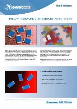
Excellent pulse handling performanceCost eectivecustom designs availableField proven with millions of units in useStandard and custom chip sizes 0805 to 2512To meet this demand TT electronics have ID: 218586
Download Pdf The PPT/PDF document "PULSE WITHSTANDING CHIP RESISTORS - Appl..." is the property of its rightful owner. Permission is granted to download and print the materials on this web site for personal, non-commercial use only, and to display it on your personal computer provided you do not modify the materials and that you retain all copyright notices contained in the materials. By downloading content from our website, you accept the terms of this agreement.


PULSE WITHSTANDING CHIP RESISTORS - Application NoteFixed ResistorsToday’s electronic devices are becoming smaller and smaller. As a result designers are moving more towards surface mount components not only for new designs but also to design out large axial and other through-hole resistors. In most cases this is a straightforward task as several resistor manufacturers o er chip resistors with performances to match axial parts. However in some cases, due to power rating or pulse withstandingrequirements, this has been impossible. The requirement, in particular, for pulse withstand capability is growing due to the need to protect sensitive modern electronic systems. Excellent pulse handling performanceCost e ectivecustom designs availableField proven with millions of units in useStandard and custom chip sizes (0805 to 2512)To meet this demand TT electronics have designed a Pulse Withstanding Chip Resistor (PWC Series). The PWC series is available in four standard sizes from 0805 to 2512 as shown in the following table. The table also gives details of the improved LEV (Limiting Element Voltage) and increased power rating. Pulse withstanding details are given on thefollowing pages.The enhanced performance of the chips is made possible by the precise use of the best resistance inks and a closely controlled production process. TT electronics companies PULSE WITHSTANDING CHIP RESISTORS - Application NoteApplicationsApplications vary from line protection for telecommunicationsto surge withstanding resistors for use in circuit breakers. Details of a typical telecomm and power supply application are given below.Telephone lines can be subjected to a large range of voltagedisturbances, many of which can damage switching equipment.This has led to the need for circuit protection against both highvoltage transients, usually of short duration caused by lightingstrikes and overloads of longer duration, due to direct connection to mains power lines. These two faults are separated into primary and secondary protection. Primary protection handles the high voltagetransients, and is usually located within the exchange. Secondaryprotection is usually built into the equipment to be protected,and deals with both current and voltage limiting.Voltage limiting prevents damage to the equipment and shock hazards, and current limiting prevents damage to wiring. A typical application circuit is shown in g 1 where the resistors are designed for ring signal sending through a solid state relay. The resistors *0.5% Tolerance only available on values 10R to 1MO. are protected from lightning surge by Over-voltage Protection in the system and the resistors are required to withstand pulses of 15 Watts for 1 second and 75 Watts for 0.1 second, repeated 60 times. Test requirements for telecomms applications are laid down by the International Telecommunications Union (ITU) and Bell Communications Research (Bellcore).Fig 2 shows a typical power supply or battery charger circuit. Inthis application the resistor is required to withstand a small inrush surge, and also a lightning strike surge. The lightning strike is usually simulated by applying either a 1.2/50 s or 10/700 s pulse shape, the number of pulses and pulse intervals being speci ed by the customer or the relevant standard. Typical standards to be met are Cenelec EN50082-1 and EN50082-2 which are part of the European EMC directives, and Bellcore 1089 for the US market.To determine the suitability of a PWC series chip resistors for your application refer to the pulse withstanding data as given below. Graphs have been produced to show the PWC performance under single and continuous pulse, maximum pulse voltage for single and continuous pulses and lighting surge performance using both 1.2/50 s and 10/700 s pulse shapes.Fixed Resistors SizePower @70°CResistance range1R0 to 10MToleranceLEVTCROperating temperature-55 to +155°CValuesE96 preferred other values to special orderPulse capabilitySee following pages Welwynsistor Vo Welwynsistor Lightning Surg PULSE WITHSTANDING CHIP RESISTORS - Application Note Fixed Resistors Description of Performance TestsSingle ImpulseThe single impulse graph was the result of 50 impulses ofrectangular shape applied at one minute intervals. The limit ofacceptance was a shift in resistance of less than 1% from theinitial value. The power applied was subject to the restrictionsof the maximum permissible impulse voltage graph as shown.Continuous Load Due toRepetitive PulsesThe continuous load graph was obtained by applying repetitiverectangular pulses where the pulse period (tp) was adjusted sothat the average power dissipated in the resistor was equal toits rated power at 70°C. Again the limit of acceptance was ashift in resistance of less than 1% from the initial value.The formula used to calculate the average power for repetitivepulses is shown below.For a rectangular impulse For an exponential impulse Where nominal resistancetime of the pulse period (1/tp = pulse frequency)peak voltage of the impulseaverage power dissipation of continuous pulsesimpulse time of a rectangular pulseTe time constant of an exponential pulse nomnom Rectangular Pulses Exponential Pulse PULSE WITHSTANDING CHIP RESISTORS - Application Note Fixed Resistors Single Pulse110100100011.010.0100.01000.0Pulse Duration ti (s)Pulse Power P (W) 0805 1206 2010 2512 Continuous Pulses0.11010011.010.0100.01000.0Pulse Duration ti (s)Pulse Power P (W) 0805 1206 2010 2512 Vo O805 1206 2010 2512 PULSE WITHSTANDING CHIP RESISTORS - Application Note Fixed Resistors µs 0805 1206 2010 2512 10100100010000111100010000100000100000010000000Value (ohms)Volts Applied µs µs 10/700µs Lightning Surge10100100010000111100010000100000100000010000000Value (ohms)Peak Voltage (Volts) 0805 1206 2010 2512 Lightning SurgeResistors are tested in accordance with IEC61000-4-5 using both 1.2/50 s and 10/700 s pulse shapes. 10 pulses are applied.The limit of acceptance is a shift in resistance of less than 1% from the initial value. www.ttelectronics.com www.bitechnologies.com www.irctt.com www.welwyn-tt.comTT electronics: leading in xed resistor technology.PULSE WITHSTANDING CHIP RESISTORS - Application NoteGeneral NoteTT electronics reserves the right to make changes in product speci cation without notice or liability.All information is subject to TT electronics’ own data and is considered accurate at time of going to print. TT electronics companies Fixed Resistors © TT electronics plc LIT-PULSE-WHTCHIP-APP Issue 2Europe:sales@ttelectronicseurope.comAsia:sales@ttelectronicsasia.comAmericas:sales@ttelectronics-na.comPerformance DataPhysical Data MaximumTypicalLoad at rated power: 1000 hours at 70°CShelf life: 12 months at room temperatureDerating from rated power at 70°CZero at 155°COverload: 6.25 x rated power for 5 secondsDry heat: 1000 hours at 155°CLong term damp heatTemperature rapid changeResistance to solder heatVoltage proofNote: An 0.01 ohm addition to be added to the performance of all resistors .Dimensions of PWC chips are given below in mm and weight in g.* This dimension determines the number of conductors which may pass under the surface mounted chip. Construction & SolderabilityThick lm resistor material, overglaze and organic protectionare screen printed on a 96% alumina substrate. Wrap-aroundterminations have an electroplated nickel barrier and tin-leadsolder coating, this ensures excellent ‘leach’ resistance properties and solderability. Chips can withstand immersion in solder at 260°C for 30 seconds. T W A A B LWrap-around terminations(3 faces)