
Instruction BulletinRetain for future use Read these instructions carefully and look at the equipment to become familiar with the device before trying to install operate service or maintain it Th ID: 823601
Download Pdf The PPT/PDF document "Three Phase, Liquid Filled, Compartmenta..." is the property of its rightful owner. Permission is granted to download and print the materials on this web site for personal, non-commercial use only, and to display it on your personal computer provided you do not modify the materials and that you retain all copyright notices contained in the materials. By downloading content from our website, you accept the terms of this agreement.


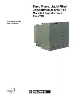
Three Phase, Liquid Filled, Compartmenta
Three Phase, Liquid Filled, Compartmental Type, Pad Mounted TransformersInstruction BulletinRetain for future use.Read these instructions carefully and look at the equipment to become familiar with the device before trying to install, operate, service, or maintain it. The following special messages may appear throughout this bulletin or on the equipment to warn of potential hazards or to call attention to information that clarifies or simplifies a procedure.The addition of either symbol to a Danger or Warning safety label indicates that an electrical hazard exists which will result in personal injury if the instructions are not followed.This is the safety alert symbol. It is used to alert you to potential personal injury hazards. Obey all safety messages that follow this symbol to avoid possible injury or death.NOTE:Provides additional information to clarify or simplify a procedure.Electrical equipment should be installed, operated, serviced, and maintained only by qualified personnel. No responsibility is assumed by Schneider Electric for any consequences arising out of the use of this material.WARRANTY TO CUSTOMERS PURCHASING THROUGH AUTHORIZED SCHNEIDER ELECTRIC DISTRIBUTORS AND CUSTOMERS PURCHASING DIRECTLY FROM SCHNEIDER ELECTRIC.Schneider Electric warrants equipment manufactured by it to be free from defects in materials and workmanship for eighteen (18) months from date of invoice from Schneider Electric or its authorized sales channels. If within the applicable warranty period purchaser discovers such item was not as warranted and promptly notifies Schneider Electric in writing, Schneider Electric shall repair or replace the items or refund the purchase price, at Schneider Electrics option. This warranty shall not apply (a) to equipment not manufactured by Schneider Electric, (b) to equipment which shall been repaired or altered by others than Schneider Electric, (c) to equipment which shall have been subjected to negligence, accident, or damage by circumstances beyond Schneider Electrics control, or to improper operation, maintenance or storage, or to other than normal use or service. With respect to equipment sold but not manufactured by Schneider Electric, the warranty obligations of Schneider Electric shall in all respects conform and be limited to the warranty actually extended
to Schneider Electric by its supplier. T
to Schneider Electric by its supplier. The foregoing warranties do not cover reimbursement for labor, transportation, removal, installation, or other expenses which may be incurred in connection with repair or replacement.Except as may be expressly provided in an authorized writing by Schneider Electric, Schneider Electric shall not be subject to any other obligations or liabilities whatsoever with respect to equipment manufactured by Schneider Electric or services rendered by Schneider Electric.THE FOREGOING WARRANTIES ARE EXCLUSIVE AND IN LIEU OF ALL OTHER EXPRESS AND IMPLIED WARRANTIES EXCEPT WARRANTIES OF TITLE, INCLUDING BUT NOT LIMITED TO IMPLIED WARRANTIES OF MERCHANTABILITY AND FITNESS FOR A PARTICULAR PURPOSE.DANGER indicates an imminently hazardous situation which, if not avoided, will result in death or serious injury.WARNING indicates a potentially hazardous situation which, if not avoided, can result in death or serious injury.CAUTION indicates a potentially hazardous situation which, if not avoided, can result in minor or moderate injury.CAUTION, used without the safety alert symbol, indicates a potentially hazardous situation which, if not avoided, can result in property damage.© 2002 2004 SchneiderElectric All Rights Reserved43500-054-03R2 Three Phase, Liquid Filled, Compartmental Type, Pad Mounted Transformers05/2004Table of ContentsENGLISHSection 1Standard Features..................................................................5Section 2Introduction............................................................................6Section 3 Safety Precautions................................................................7Section 4Receiving, Handling, and Storage........................................8Receiving ...............................................................................................8Initial Inspection............................................................................... 8Internal Inspection........................................................................... 9Liquid Sampling............................................................................... 9Liquid Level Inspection.................................................................... 9Handling ..................................................................................
............10Unloading and Lifting.....
............10Unloading and Lifting..................................................................... 10Storing .................................................................................................11Section 5Installation............................................................................12Transformer Location ..........................................................................12Restricting Access to the Transformer ................................................12Grounding ......................13Conduit Area .......................................................................................13Cable Pulling .......................................................................................13Cable Terminations Using Unshielded Cable ......................................13Cable Terminations Using Shielded Cabl.......14Electrical Connections ............14High Voltage Bushing Connections ..............15Low Voltage Bushing Connections ......................................................16Section 6Operation..............................................................................16Tap Changer .......................................................................................16Dual Voltage or Delta/Wye Switch Operation ................17Parking Stands ....................................................................................17Live-Line Tools (Hot Sticks) ................................................................18Load Break Switch Operation ..............................................................18Fuses ...................................................................................................19Bay-O-Net Fuse Operation............................................................ 19Dry Well Canister Fuse Operation .......................................................21Load-Break Fuse Operation.......................................................... 21Non-Load-Break Fuse Operation.................................................. 21Internal Partial Range Current-Limiting Fuse ......................................22Arc-Strangler Switch Operation ...........................................................22Weak Link Fuses .................................................................................23S & C Fused Switch ...
........................................
.........................................................................23Accessories .........................................................................................23Dial Thermometer.......................................................................... 23Liquid Level Gauge................ 24Pressure Vacuum Gauge.............................................................. 24Pressure Relief Valve.................................................................... 24Drain Valve With Sampler............................................................. 25Surge Arrestors............................................................................. 25Current Transformers.................................................................... 25Molded Case Circuit Breakers....................................................... 25Section 7Start-Up Testing...................................................................26Pre-energization Tests ........................................................................26Wye-Wye Transformers With HOXO Bushing .....................................26Insulation Resistance Testing........................................................ 26Turns Ratio Test............................................................................ 27Three Phase, Liquid Filled, Compartmental Type, Pad Mounted Transformers 43500-054-03R2Table of Contents© 2002 2004 SchneiderElectric All Rights ReservedPre-Energizing Procedure Checklist ............27Verifying the Voltage is Correct ...........................................................29Inspection Following Energizing ..........................................................29Sound Level .....................29Cabinet Security ..................................................................................30..........................................................................30Scheduled Maintenance ......................................................................30Maintenance Testing...................................................................... 31Maintenance for Accessories ...................31Molded Case Circuit Breakers Inspection and Maintenance ...............31Ground Fault Protection Systems ........................................................32Maintenance After a Major Fault ........
......32Exterior Finish ................
......32Exterior Finish ......................................................................................33Locating Pressure Leaks Above the Liquid Level.......................... 33Liquid Leaks ........................................................................................33Small Pin-Hole Leaks ..........................................................................34Bushing Leaks .....................................................................................34Maintenance of Internal Features ..............34Sampling the Liquid....................................................................... 34Receiving, Storing, and Handling the Liquid.................................. 35Draining and Filling the Tank......................................................... 35Opening the Transformer Tank...................................................... 36Entering the Transformer Tank...................................................... 37Closing the Transformer Tank....................................................... 37Repairs .................37Section 9Replacement Parts...............................................................38Section 10Reference Publications......................................................38Figure1:External Features ..................................................................5Figure2:Terminal Compartment Features ...........................................5Figure3:Lifting the Transformer .........................................................11Figure4:Dual Voltage Switch .....................17Figure5:Bay-O-Net Expulsion Fuse and Holder with Isolation Link ..20Figure6:Bay-O-Net Current Limiting Full Range Fuse and Holder ...20Figure7:Load-Break Drawout Fuseholders .......................................21Figure8:Dead-Break Drawout Fuseholders ......................................21Figure9:Arc Strangler ................22Figure10:Fused Arc-Strangler .............................................................22Figure11:Arc-Strangler with Clip Fuse ........22Figure12:Expulsion Type Fuse ...........................................................23Figure13:Instantaneous Trip Setting ...................................................25Table1:Torque Guidelines............................................................... 15Table2:QED-3 Cir
cuit Breaker Connector Bolts............
cuit Breaker Connector Bolts.............................. 15Table3:Liquid Level Gauge.............................................................. 24Table4:Blank Fillers and Extensions........ 28Table5:Installation Instructions........................................................ 38Table6:Instruction and Maintenance Bulletins...................... 39Table7:Ground Fault Field Test Instructions...................... 39Table8:Distribution Reference Catalogs.......................................... 39Table9:Other Reference Literature.................................................. 3943500-054-03R2 Three Phase, Liquid Filled, Compartmental Type, Pad Mounted Transformers05/2004Section 1Standard Features© 2002 2004 SchneiderElectric All Rights Reserved5ENGLISHSECTION 1STANDARD FEATURESThe pad mounted transformer differs from the substation or pole-style transformer by its applications and external appearance. Designed for application with underground feeders, the pad mounted transformer is tamper resistant and compartmentalized on the front.Figure1:External FeaturesLifting lugsLift-off hinges on doorsRadiators or cooling panels on sides and rear (as required)Tank base designed for jacking, rolling, or skiddingCorrosion-resistant undercoatingRemovable terminal compartmentRemovable sillPadlockable door handlePaint finish: olive green, Munsell no. 7GY3.29/1.5Figure2:Terminal Compartment FeaturesLow voltage bushing spades. Externally removable. (Removable ground strap provided on bushing of wye-connected units.)Neutral grounding strapSteel barrier between HV and LV compartments750 5000kVA: 1in. drain valve with sampling device (shown);75 500kVA: 1in. drain plugPressure vacuum gauge1/4in. pressure relief valveDial-type thermometerHigh voltage bushings; externally removable. Dead front radial feed configuration shown.Tap changer handle1in. filling plug and filter press connectionLiquid level gaugeNameplateDual voltage switch(optional)Bay-O-Net fuses(optional)Three Phase, Liquid Filled, Compartmental Type, Pad Mounted Transformers 43500-054-03R2Section 1Introduction© 2002 2004 SchneiderElectric All Rights ReservedThis instruction bulletin details information about installing, operating, and maintaining liquid filled, compartmental type, pad mounted transformers. Each transformer has its own
specification and unique construction f
specification and unique construction features. These features are detailed in the transformer outline and nameplate drawings.This instruction bulletin is not an application guide for the transformer or a substitute for adequate training in safe working procedures for this and related electrical equipment. Installation of this electrical equipment may require special licenses or training. Consult applicable national, industry, and local codes for specific requirements.The successful operation of any transformer depends on various factors such as installation, loading, service conditions, and maintenance. Electrical systems in which transformers circuit breakers, are used are capable of high frequency overvoltages which will not be suppressed by lightning arrestors. These medium voltage systems may require a detailed, high frequency overvoltage system analysis and/or the addition of high frequency overvoltage protection. The transformer should be installed in conditions as specified in ANSI/IEEE Section C57.12.00 Usual Service Conditions, unless the transformer is designed specifically for operation in conditions other than the usual service conditions.NOTE:If additional information is needed that is not covered by this instruction bulletin, contact the nearest Schneider Electric field sales representative, or Square D Services at 1-800-634-2003.43500-054-03R2 Three Phase, Liquid Filled, Compartmental Type, Pad Mounted Transformers05/2004Section 3SafetyPrecautions© 2002 2004 SchneiderElectric All Rights Reserved7ENGLISHSECTION 3 SAFETY PRECAUTIONSDo not remove, paint over, or cover the warning labels and nameplates on the transformer.DANGERHAZARD OF ELECTRIC SHOCK, EXPLOSION, OR ARC FLASHApply appropriate personal protective equipment (PPE) and follow safe electrical work practices. See NFPA 70E.Read and understand this entire instruction bulletin before installing, operating, or maintaining a liquid filled transformer. Follow all applicable local and national codes.Disconnect all power and verify the transformer is de-energized before servicing the transformer. Operation of a primary protective device may be evidence of a faulted transformer. Do not re-energize the transformer until the cause of operation of the primary protective device is found and Many parts of the transformer operate
at high voltages. DO NOT TOUCH. Use only
at high voltages. DO NOT TOUCH. Use only electrically insulated tools and clothing, and protective gear when working around electrical equipment.Do not rely on visual indications such as switch position or fuse removal for determining a de-energized condition. Always assume that a terminal is energized unless it is checked with a properly rated meter to ensure the terminal is de-energized and grounded.Before servicing the transformer, ensure all static charge has been discharged by grounding the coils with an appropriate grounding device.This equipment must only be installed and serviced by qualified electrical personnel.Turn off all power supplying this equipment before working on or inside equipment.Always use a properly rated voltage sensing device to confirm power is Replace all devices, doors, and covers before turning on power to this equipment.Failure to follow these instructions will result in death or serious injury.Three Phase, Liquid Filled, Compartmental Type, Pad Mounted Transformers 43500-054-03R2Section 4Receiving, Handling, and Storage© 2002 2004 SchneiderElectric All Rights ReservedThis transformer has been furnished with a pentahead locking bolt that must be loosened to open the compartment. This bolt can be turned with a standard pentahead socket wrench, as used widely in the utility industry. Sockets can be obtained from the Snap-On Company (tool #B2191) or from other tool distributors.ReceivingInitial InspectionBefore unloading the transformer, follow steps 1 3:1.Verify that the serial number on the transformer nameplate matches the serial number listed on the bill of lading. If the numbers do not match, contact your local Schneider Electric field sales representative immediately.2.Review the shipping papers to ensure the shipment is complete. Accessories, hardware, or both may arrive in a separate container on a separate pallet. Claims for shortages or errors must be made in writing to Schneider Electric within 60 days after delivery. Failure to give such notice will constitute unqualified acceptance and a waiver of all such claims by the purchaser.For details concerning claims for equipment shortages and other errors, refer to the Schneider Electric Terms and Conditions of Sale.3.Before unloading the transformer, complete external features checks a f:a.Check for an
y obvious dents or scratches in the tank
y obvious dents or scratches in the tank walls or cooling radiator. Such dents and/or scratches in the paint finish can most often be corrected by simple touch-up procedures (see Exterior Finish on page33).b.Check for liquid coolant leaks. Look for oily streaks on the transformer surface, at weld seams, on high or low voltage bushing parts, and any collection of the insulating coolant at the base of the transformer. If found, investigate them thoroughly to determine if a leak does exist on the transformer. A pinhole leak or any bushing leak resulting in a very slow loss of liquid is field repairable. Refer to pages 33 34 for information on repairing leaks.c.Check for broken, cracked, or damaged bushings.d.Check for missing or damaged parts, or packaging which shipped separately from the transformer.e.Check the nameplate for design compliance. Voltage, kVA ratings, percentage impedance voltage (%IZ), and other design features must comply with the job specification and outline drawing.f.Check for accessory features by reviewing shipping papers, outline and wiring drawings, instruction bulletins, and other pertinent documents that are supplied with the transformer. The transformer outline drawing for the specific order indicates which accessories should be present and their location on the unit.43500-054-03R2 Three Phase, Liquid Filled, Compartmental Type, Pad Mounted Transformers05/2004Section 4Receiving, Handling, and Storage© 2002 2004 SchneiderElectric All Rights Reserved9ENGLISHInternal InspectionThe objective of the internal inspection is to locate any damage which might have occurred in shipment. In most cases, an inspece internal tank is rarely necessary and is required only if there is obvious indication the tank has sustained severe impact damage in transit. Do not perform an internal inspection unless authorized by Schneider Pay particular attention to leads, bolted mechanical and electrical joints, tap changers, current transformers, cores, and insulation structure. If removing the maintenance hand hole cover is necessary, refer to Opening the Transformer Tank on page36.The tank has been sealed at the factory to eliminate any possibility of contamination of the liquid coolant by moisture. The accumulation of moisture over time can destroy the insulating properties of the liquid co
olant. Therefore, if the transformer is
olant. Therefore, if the transformer is opened for internal inspection, do not leave it open for longer than two hours. Initial inspection of the pressure seal is necessary and can be accomplished by either of the following methods. Consult your local Schneider Electric field sales representative before performing any repairs.1.Observe the pressure/vacuum gauge. A consistent rise and fall in pressure readings with the rise and fall of liquid coolant and ambient temperature demonstrates an effective seal. A flat or unchanged reading over time and at varying temperatures is evidence of a leak that must be located and repaired. Refer to Locating Pressure Leaks Above the Liquid Level on page33.2.Pull the pressure relief valve ring momentarily, or loosen the vent plug. The sound of rushing air is an indication the unit has maintained an effective seal. If there is no sound of rushing air, the seal may still be effective, as this may only be an indication that the ambient temperature has decreased sufficiently to lower the pressure to zero. If this is the case, repeat this test at a time of day when the temperature is significantly different. If it is apparent the internal pressure is remaining unchanged following this procedure, review Maintenance of Internal Features on page34 before locating and repairing any leak.Liquid SamplingAn initial visual inspection and testing of the liquid insulating coolant is not required unless there is indication that moisture or other contaminants have accidently entered the tank during transit. If there are indications of moisture in the insulation, contact your Schneider Electric field sales representative immediately for confirmation of the analysis and for recommendations on the drying procedure to be followed. If sampling the liquid coolant is required, see Sampling the Liquid on page34.Liquid Level InspectionThe transformer is shipped with the liquid coolant at the correct operation level. Verify this when the transformer is received by reading the level from the level gauge. The indicator should be halfway between the 25° C mark and the high or the low mark.WARNINGHAZARD OF ELECTRIC SHOCK, EXPLOSION, OR ARC FLASHDo not energize transformer if the liquid level is low.Maintain the proper liquid level when the transformer is energized.Failure to follow
these instructions can result in death o
these instructions can result in death or serious injury and damage to equipment.Three Phase, Liquid Filled, Compartmental Type, Pad Mounted Transformers 43500-054-03R2Section 4Receiving, Handling, and Storage© 2002 2004 SchneiderElectric All Rights ReservedIf the transformer is shipped without a liquid level gauge, the liquid level should be checked by removing the liquid level plug located at the 25° C mark. Any unit which does not have the proper liquid level should be checked for leaks and refilled through the vent plug before placing it in service. Refill only with the same type of liquid as that specified on the transformer nameplate.The transformer was filled or processed at the factory with non-polychlorinated biphenyl (PCB) dielectric fluid in accordance with federal PCB regulations 40 CFR 761, et seq. The non-PCB fluid contained less than 1 ppm at time of processing or filling. The owner should take the necessary precautions so that PCB contamination is not introduced during field filling or maintenance of the transformer.Consult your Schneider Electric field sales representative if the level is not HandlingThe transformer is shipped on an open carrier trailer to facilitate the use of a crane for unloading. Unloading the unit with a forklift is NOT recommended since the weights are often excessive and the coolant radiators are easily damaged. The transformer must be handled in the normal upright position to avoid internal stresses on the core and coil mounting assembly and to prevent trapping air in the windings that could create serious problems when the transformer is energized. The transformer weight is shown on the nameplate.Unloading and LiftingLifting hooks or lugs are provided for lifting the complete transformer. When using a single point hitch (see Figure3 on page11), the angle between the cables (when viewed from the front or long side of the transformer) must not exceed 60 degrees. If the cables are at least as long as the longest dimension of the transformer tank, the angle will not exceed the maximum. NOTE:Do not use the holes in the lifting hook on the transformer (if provided) for lifting.DANGERHAZARD OF FALLING EQUIPMENT AND CRUSHINGUse a crane to unload the transformer. DO NOT UNLOAD using a forklift. The transformer is top heavy and may become unbalanced.Keep all u
nnecessary personnel away while handling
nnecessary personnel away while handling and moving the Failure to follow these instructions will result in death or serious injury.43500-054-03R2 Three Phase, Liquid Filled, Compartmental Type, Pad Mounted Transformers05/2004Section 4Receiving, Handling, and Storage© 2002 2004 SchneiderElectric All Rights Reserved11ENGLISHJacking may be accomplished at the corners of the tank base plate. Do not attempt to raise the transformer by placing jacks under drain valves, pipe connections, or other attachments. When jacking, use all of the jacking pads. Never attempt to lift the transformer by using cranes or jacks on any part of the transformer other than the fittings provided for this purpose. When the transformer cannot be handled by a crane, it may be skidded or moved on rollers, but be careful not to damage the tank base structure. When using rollers under large transformers, use skids to distribute the stress over the tank base.StoringIf the transformer must be stored, it should be stored completely assembled, preferably in its permanent location on the concrete pad. If a level concrete pad is not available, a pallet of adequate strength will keep the unit from direct contact with the ground. Maintain adequate ventilation underneath the transformer. Do not store the transformer in the presence of corrosive gases such as chlorine, acid fumes, etc. Periodically inspect the stored transformer just as a unit that is in service. Ensure that an effective pressure seal is maintained and check for leaks and any rust spots.Transformers should not be stacked on top of one another. Exercise care to prevent submersion in water.If a transformer is to be stored more than one year, pressurize the gas space above the liquid with dry nitrogen between 2 3 PSIG. This will prevent moisture from being pulled into the tank by a negative pressure.Figure3:Lifting the TransformerSpreader BarLifting HookSling MaximumThree Phase, Liquid Filled, Compartmental Type, Pad Mounted Transformers 43500-054-03R2Section 5Installation© 2002 2004 SchneiderElectric All Rights ReservedSECTION 5INSTALLATIONNOTE:Complete start-up services are available from Square D Services. They can provide assistance in a variety of areas, from installation to comprehensive testing and verification of the new equipment. Contact Square D Service
s at 1-800-634-2003, 24-hours a day.Ship
s at 1-800-634-2003, 24-hours a day.Shipping braces may be used to secure the unit while it is transported. There are two kinds: those that do not interfere with the operation of the transformer and need not be removed, and those that must be removed for electrical clearances or other reasons. Always check the notes on the outline drawings for instructions on shipping braces that must be removed.Transformer LocationFollow all local and national codes when locating the transformer. Make sure the radiators are clear of obstructions. The transformer must be at least 24 inches (710 mm) from walls or other obstructions to allow circulation of air around each unit.For indoor installations, consult local and national codes to ensure all applicable requirements are satisfied. If the transformer is located near combustible materials, make sure the transformer meets or exceeds the minimum clearances as required by the National Electrical Codeother applicable local codes.Place transformer on a foundation of sufficient strength to support the weight of the transformer, preferably of reinforced concrete. The transformer cabinet should sit flush on the pad, allowing no gaps which would compromise the tamper resistance of the transformer. Do not place the transformer directly on an earthen surface. Ensure the foundation has adequate drainage. Seismic regulations may require that the transformer be anchored to the pad. When supplied, hold-down cleats or brackets should be used to bolt the transformer securely to the pad.The unit should not be tilted in any direction grater than 1.5°, as a greater tilt will cause deviations in liquid level near fuses, pressure relief devices, or other accessories specifically located at or near the 25° C liquid level.At altitudes above 3300ft. (1006m), the decreased air density reduces the transformer cooling efficiency and bushing BIL rating. Contact your local Schneider Electric field sales representative to verify the suitability of the unit for application at higher altitudes.Restricting Access to the TransformerCompartmental-type pad mounted transformers are designed and constructed to be tamper-resistant and therefore need not be located in a restricted area. However, if for any reason modifications are made to the transformer or compartment that compromise the tamper-resistan
t construction, the transformer must the
t construction, the transformer must then be located in a restricted area. Modifications of this type may void the warranty. Consult your local Schneider Electric field sales representative before making any modifications to the transformer.DANGERHAZARD OF ELECTRIC SHOCK, EXPLOSION, OR ARC FLASHDo not make modifications to the transformer or compartment that will ng the tamper-resistant construction.Failure to follow this instruction will result in death or serious injury.43500-054-03R2 Three Phase, Liquid Filled, Compartmental Type, Pad Mounted Transformers05/2004Section 5Installation© 2002 2004 SchneiderElectric All Rights Reserved13ENGLISHGroundingGround the transformer tank at all times. To ground the tank permanently, use ground pads or nuts at the base of the tank wall in both the high- and low-voltage compartments. A good permanent, low-resistance ground is essential for adequate protection from the tank becoming momentarily energized by internal or external faults or lightning surges. Do not use cubicle hold-down bolts, cleats, or any other plug fitting to establish a tank ground.Conduit Area1.Locate and terminate all conduit in the transformer enclosure in the available conduit area designated on the equipment drawing.2.Install the conduit properly. Use hubs and ring connectors to protect the cables.NOTE:If top entry (such as bus duct), do not use the top of the compartment to support the weight of the conduit or bus duct. Support the conduit or bus duct independently.Under seismic conditions, the top of the compartment can move as much as 3 inches (76 mm) in any direction. Any top incoming cables this motion.3.Bond all conduit, stubs, and ring connectors to the transformer ground with approved electrical connections.Cable Pulling1.Use only cable sizes suitable for a proper fit with the corresponding lugs.2.Pull the proper number of line-side and load-side cables according to the load served and the NEC.3.Position the cables inside the compartment so that they are not subject to physical damage.4.Maintain the maximum possible bending radii and proper clearance to grounded parts. If any cables are lying or bearing on structural members, support them to relieve this condition or place suitable protective material at the bearing point to protect the cable insulation.Cable Terminations
UsingUnshielded Cable1.Strip a length of
UsingUnshielded Cable1.Strip a length of insulation from the end of the cable sufficient to fit into the full length of the lug barrel, being careful not to nick or ring the strands. Use a proper insulation stripping tool.2.Thoroughly clean aluminum cable contact surfaces with a wire brush or scrub them with an abrasive cloth to remove oxides and foreign matter.3.Immediately apply an acceptable joint compound to the bare aluminum DANGERHAZARD OF ELECTRIC SHOCK, EXPLOSION, OR ARC FLASHFollow all applicable codes for grounding all equipment. Ensure proper grounding. Improper grounding can cause high voltage on the transformer tank and secondary terminals.Failure to follow this instruction will result in death or serious injury.Three Phase, Liquid Filled, Compartmental Type, Pad Mounted Transformers 43500-054-03R2Section 5Installation© 2002 2004 SchneiderElectric All Rights Reserved4.If compression-type lugs are furnished on any switch or circuit breaker, or as the main incoming power lugs, unbolt and remove them to create sufficient room for crimping the lugs to the cables with the crimping tool.a.Insert the cable into the lug barrel and, using the crimping tool, make the specified number of crimps per the manufacturers recommendations.b.Wipe excess joint compound from the connector and insulation.c.With the cables connected, remount the lugs onto the bushings, switches, or circuit breakers. Torque the bolts to the values given in Electrical Connections below.5.Set screw-type lugs are standard on molded case circuit breakers. Torque these lugs to, but do not exceed, the specified values. Torque values for circuit breaker and switch lugs are marked on these units. Cable Terminations UsingShielded CableFor live front transformers, install properly rated cable stress relief terminator kits on each cable. Follow the instructions provided with the stress relief terminator kit. Install the terminator so the top of the terminator (live part) is at approximately the same height as the top of the lightning arrestors, if provided.For dead front transformers, use properly rated elbow terminators sized to fit the high voltage bushings. Follow the installation instructions provided with the elbow terminators.Electrical ConnectionsAll mating joints of electrical connections must be clean and properly tighte
ned. Ensure that there are no strains on
ned. Ensure that there are no strains on the terminals that could cause loose connections. See Table 1 and Table 2 on page 15 for the recommended torque values.Make external electrical connections in such a way as not to exceed a cantilever load of 100lb (45 kg) on the bushings. Greater loads may cause bushing damage. Inspect the bushing periodically for broken or cracked porcelain and faulty gaskets.43500-054-03R2 Three Phase, Liquid Filled, Compartmental Type, Pad Mounted Transformers05/2004Section 5Installation© 2002 2004 SchneiderElectric All Rights Reserved15ENGLISHHigh Voltage Bushing ConnectionsHigh voltage bushings are provided according to the job specification as either porcelain live-front with exposed metal eyebolt terminals or as a molded dead-front. Lugs are not required to terminate the cable on a live front bushing. However, with the live front design and the use of shielded cable, a cable stress relief terminator kit must be installed on each high voltage cable. An elbow terminator kit must be installed on the cable to permit connection to the dead front bushing. On the dead front design, the elbow terminator kit includes the necessary cable stress relief. Contact your local Schneider Electric field sales representative for application or order information on the live front or dead front terminator kits. Installation instructions are provided with the terminator kits.The one-piece integrated bushing is shipped with a plastic protective cap that should be left in place until the transformer is energized to avoid dirt or moisture contaminating the internal bushing contact points. On an energized transformer, a ground cap must be plugged onto any unused bushing well or insert to avoid partial discharge and subsequent bushing damage.The transformer nameplate illustrates the internal wiring and external marking of each bushing. Refer to the nameplate on the transformer for clarity on where to connect each incoming cable.On live front designs, ensure adequate air clearances between all live parts.Table1:Torque GuidelinesBolt SizeGeneral Torque Valueslb-ft (Nm)18-8 Stainless Steellb-ft (Nm)Silicon Bronzelb-ft (Nm)1/4-204 6 (5 8)4 6 (5 8)4 6 (5 8)5/16-186 12 (8 16)6 12 (8 16)6 12 (8 16)3/8-1615 20 (20 27)15 20 (20 27)15 20 (20 27)1/2-1325 30 (34 41)25 30 (34 41)Table2:QED-3 Circuit
Breaker Connector BoltsCircuit Breaker T
Breaker Connector BoltsCircuit Breaker TypeTorque ValueLine/Load Connector Boltslb-in FA, FH, FC, FI55 65 (6 7)KA, KH, KC, KI65 75 (7 8)LA, LH145 160 (16 18)MA, MH, MX, ME130 150 (15 17)NA, NC, NX, NE130 150 (15 17)WARNINGHAZARD OF ELECTRIC SHOCK, EXPLOSION, OR ARC FLASHUnused dead front bushings that are energized must be properly terminated with a grounding cap.Failure to follow this instruction can result in death or serious injury and damage to equipment.Three Phase, Liquid Filled, Compartmental Type, Pad Mounted Transformers 43500-054-03R2Section 6Operation© 2002 2004 SchneiderElectric All Rights ReservedLow Voltage Bushing ConnectionsLow voltage bushings through 600 volts are supplied with NEMA standard hole drillings and spacings but are not supplied with lugs. Lugs may be stacked or mounted on either face of the spade. A minimum 1in. (25.4mm) air clearance must be maintained between live parts, phase-to-phase and phase to ground for 600 volts or less.Low voltage terminations are high current carrying devices. All bolted or crimped points should be checked prior to energizing the unit to ensure the joints are tight. When threaded terminators are attached to the threaded secondary stud, install a backup nut on the threaded secondary stud and back it up tightly against the threaded terminator to ensure maximum contact and to minimize joint resistance and reduce the possibility of overheating.Tap ChangerThe no-load, de-energized tap changer is provided to adjust the output voltage to its rated voltage. Do not use it to raise or lower the output (secondary) voltage to any voltage other than the rating appearing on the nameplate. If the tap changer is used to set the voltage different from the rated voltage, it will result in a high noise level, higher core loss, and The no-load tap changer is provided with an operating handle, tap position indicator, and provision for padlocking. Some no-load tap changers may have provisions for a Kirk Key, or equivalent, interlock system.Before energizing or applying voltage to the transformer, turn the tap changer to the desired voltage position. Positions are marked 1, 2, 3, 4, and 5 (or A, B, C, D, and E), and correspond to the primary voltages stamped on the transformer nameplate. The unit is shipped with the tap switch in the rated voltage position, n
ormally position 3 (or C). Each position
ormally position 3 (or C). Each position changes the primary-to-secondary winding ratio by 2.5% and can alter the secondary voltage by this increment. Tap positions of 2.5% are typical but not the rule. Other percentages are supplied as required.To raise the secondary voltage, move the tap switch to position 4 (or D) or 5 (or E). To lower the secondary voltage, move the tap switch to position 1 (or A) or 2 (or B).To change the voltage position, perform the following steps:1.Make sure the transformer is de-energized.2.Back out the locking screw until it is clear of the locking hole.3.Turn the operating handle to the desired tap position.4.Re-tighten the locking screw to minimize the possibility of unintentional movement.Some large-size units are furnished with a power-transformer tap changer drive which requires pulling of a locking pin and a full turn of the handle for each change in tap position.DANGERHAZARD OF ELECTRIC SHOCK, EXPLOSION, OR ARC FLASHDe-energize the transformer before operating the tap changer.Failure to follow this instruction will result in death or serious injury and damage to equipment.43500-054-03R2 Three Phase, Liquid Filled, Compartmental Type, Pad Mounted Transformers05/2004Section 6Operation© 2002 2004 SchneiderElectric All Rights Reserved17ENGLISHDual Voltage or Delta/Wye Switch OperationTransformers designed with dual voltage windings or reconnectable delta/wye windings as indicated on the nameplate have a de-energized, two-position, dual voltage or delta/wye switch. The voltage source must be disconnected before operating the hand-operated switch. If the voltage source is not disconnected before the switch is operated, the transformer will be permanently damaged.On a dual voltage switch (see Figure 4), position 1 is the low (or multiple connected) position, while position 2 is the high (or series connected) position. To change the voltage position, perform the following steps:1.Make sure the transformer is de-energized.2.Back out the locking screw until it is clear of the locking hole.3.Pull out the handle until it will rotate.4.Turn the operating handle to the new position.5.Release the handle.6.Re-tighten the locking screw to minimize the possibility of unintentional Parking StandsParking stands, or brackets, are provided with dead-front bushings, and are located
next to the bushings. These brackets pro
next to the bushings. These brackets provide a storage location for parking bushings, to be used for storage of disengaged elbow terminators.DANGERHAZARD OF ELECTRIC SHOCK, EXPLOSION, OR ARC FLASHDe-energize the transformer before operating the dual voltage or delta/wye switch.Failure to follow this instruction will result in death or serious injury and damage to equipment.WARNINGHAZARD OF ELECTRIC SHOCK, EXPLOSION, OR ARC FLASHWhen changing the dual voltage switch, replace fuses with those of the proper rating before energizing the transformer.Failure to follow this instruction can result in death or serious injury and damage to equipment.Figure4:Dual WARNINGHAZARD OF ELECTRIC SHOCK, EXPLOSION, OR ARC FLASHUnused dead front bushings that are energized must be properly terminated with a grounding cap.Failure to follow this instruction can result in death or serious injury and damage to equipment.Three Phase, Liquid Filled, Compartmental Type, Pad Mounted Transformers 43500-054-03R2Section 6Operation© 2002 2004 SchneiderElectric All Rights ReservedLive-Line Tools (Hot Sticks)Some devices such as load-break under-liquid switches, Bay-O-Net fuses, dry well canister fuses, and dead front elbow terminators are designed to be operated with live-line tools un sticks or hot sticks. Before using any live-line tool, it must be wiped clean, and inspected and tested per OSHA 1910.269(j).Follow the instructions of the live-line tool manufacturer for proper operation. Do not attempt to operate by hand any device that is designed to be operated with a live-line tool.Load Break Switch OperationIf provided, a spring-loaded, gang-operated, load-break under-liquid switch is located in the high voltage compartment. This switch is either a two-position (ON-OFF) switch or a three- or four-position switch and is operated with a live-line tool (hot stick). The switch positions are marked on the tank front plate and shown on the transformer nameplate.The two-position switch is operated by inserting the hot stick into the operating handle and rotating the switch to either the ON or OFF position.The three- or four-position switch is index plate and moving the plate ovand the next setting. The index plate prevents the switch from switching more than 90°, or one position at a time. Next, insert the hot stick into t
he handle of the switch and turn it appr
he handle of the switch and turn it approximately 180° until the switch snaps into the next position. (Do not stop and reverse direction of the switch until it has changed position, as this will damage the switch mechanism.)until the switch is in the desired position.DANGERHAZARDOUS VOLTAGE. HAZARD OF ELECTRIC SHOCK, EXPLOSION, OR ARC FLASHDo not attempt to operate by hand any device that is designed to be operated by a live-line tool.Do not use any live-line tools that have not been inspected and tested in accordance with OSHA 1910.269(j).Failure to follow these instructions will result in death or serious injuryCAUTIONRISK OF EQUIPMENT DAMAGEDo not stop and reverse direction of the switch until it has changed position.Failure to follow this instruction will result in equipment damage.43500-054-03R2 Three Phase, Liquid Filled, Compartmental Type, Pad Mounted Transformers05/2004Section 6Operation© 2002 2004 SchneiderElectric All Rights Reserved19ENGLISHFusesOperation of a fuse may indicate a faulted transformer. Do not replace the fuse unless the cause of the fuse operation has been positively identified and corrected. If the cause of the fuse operation cannot be positively identified, contact Schneider Electric before testing or energizing the transformer.Fuses should be operated within their ratings. Replacement fuses must have the equivalent voltage and time-current characteristics of the original fuses.Bay-O-Net Fuse OperationThe Bay-O-Net fuse is a dead-front, individual-phase disconnect device that is load-break rated and operated by a live-line tool (hot stick). This type of fuse is located in the high voltage compartment above the primary bushings. The Bay-O-Net fuse can be either an expulsion type or a full range current-limiting type fuse (Figures 5 and 6). Before energizing, ensure the Bay-O-Net fuse is properly latched into place.DANGERHAZARD OF ELECTRIC SHOCK, EXPLOSION, OR ARC FLASHCompletely de-energize the transformer before replacing fuses.Do not energize or de-energize the transformer with single phase switches or fuses.Use only ganged three phase switches to energize or de-energize the transformer.Do not operate the transformer with any phases open.Only qualified personnel with appropriate measurement devices should measure the voltages on the transformer.Failure to
follow these instructions will result i
follow these instructions will result in death, personal injury, or damage to the equipment.WARNINGRISK OF ELECTRIC SHOCK, EXPLOSION, OR ARC FLASHOperation of a fuse may indicated a faulted transformer. Do not replace the fuse unless the cause of the fuse operation has been positively identified and corrected.Failure to follow this instruction can result in death or serious injury and damage to equipment.Three Phase, Liquid Filled, Compartmental Type, Pad Mounted Transformers 43500-054-03R2Section 6Operation© 2002 2004 SchneiderElectric All Rights ReservedTo operate the Bay-O-Net Loadbreak Fuseholders, on some models you must first raise the hinged, flip-top weather cover.1.With both cabinet doors fully open (over 90°), push upward on the front edge of the cover assembly.2.Tilt the hinged cover backward until the supporting arm (connected to the high-low barrier) can be securely latched in place on the inside of the cover.With the cover in place, proceed with the operating instructions for the Bay-O-Net Loadbreak Fuseholder.Remove Fuseholder1.Vent the transformer by operating the pressure relief valve. See Pressure Relief Valve on page24.2.Attach a live-line tool to the handle eye.3.Stand to one side and unlock the handle.4.Push down and rotate the handle 90° clockwise in the housing to break any adhesion between the gasket and the housing.5.Firmly pull the fuseholder out approximately 6 in. to open the circuit. Wait a few seconds while the liquid drains back into the tank, then completely withdraw the fuseholder.Replace FuseReplace the fuse by following the fuse manufacturers instructions that are shipped with the fuse.Reinstall Fuseholder1.Attach a live-line tool to the handle eye.2.Stand to one side and place the end of the fuseholder just inside the housing.3.Quickly push the fuseholder in until the dust cap seats against the housing.4.Push down and rotate the locking handle, hooking it over the shoulder of the housing.When the Bay-O-Net operations are complete, close the hinged weather cover, when provided, as follows:1.Release the latch on the hinged weather cover by tilting the cover slightly backwards.2.Lower the cover, making sure it is all the way down. (The upper high-voltage door bolt should engage through the hole in the hinged weather cover.)Figure5:Bay-O-Net Expulsion Fuse a
nd Holder with Isolation LinkFigure6:Bay
nd Holder with Isolation LinkFigure6:Bay-O-Net CuRange Fuse and HolderInternal isolation linkOperating hook and latchOperating hook and latchHAZARD OF FUSE AND LIQUID EXPULSIONRelease built-up air pressure in the tank before removing the fuse.Failure to follow this instruction will result in death or serious injury.DANGER43500-054-03R2 Three Phase, Liquid Filled, Compartmental Type, Pad Mounted Transformers05/2004Section 6Operation© 2002 2004 SchneiderElectric All Rights Reserved21ENGLISHDry Well Canister Fuse OperationThe dry well canister is a fluid-tight, current-limiting fuse holder that extends under fluid into the tank above the high voltage bushings.The canister fuse normally supplied is a non-load-break-and-make, individually-phased fuse device. If required, the dry well canister is supplied in conjunction with a mechanical interlock to a load-break switch (see Load Break Switch Operation on page18) that prevents removal of the fuse unless the switch is in the OFF or de-energized position. When required, a load break-and-make rated canister is supplied (not available on all kVA sizes.)Load-Break Fuse OperationTo operate or change fuses in load-break fuseholders, follow these instructions:Load Break1.Attach a live-line tool to the hook eye.2.Quickly pull the fuseholder assembly completely from the housing.Replace Fuse1.Unscrew the fuse from the insulating bayonet and contact probe.2.Replace with new fuse of equivalent rating and characteristics.3.Tightly screw the new fuse onto the insulating bayonet and contact probe.1.Attach a live-line tool to the hook eye.2.Insert the end of the fuseholder until the contact spring has just entered the housing.3.Quickly push the fuseholder assembly straight into the housing in until the dust cap seats against the housing and grounding clip.Non-Load-Break Fuse OperationTo operate or change fuses in non-load-break (dead-break) fuseholders, follow these instructions:Remove Fuseholder1.Attach a live-line tool to the hook eye.2.Pull the fuseholder straight out from the housing.Replace Fuse1.Unscrew the fuse from the insulating bayonet.2.Replace with new fuse of equivalent rating and characteristics.3.Tightly screw the new fuse onto the insulating bayonet.Reinstall Fuseholder1.Attach a live-line tool to the hook eye.2.Insert the fuseholder into the h
ousing.3.Push the fuseholder in firmly u
ousing.3.Push the fuseholder in firmly until the dust cap seats against the housing and grounding clip.DANGERHAZARD OF ELECTRIC SHOCK, EXPLOSION, OR ARC FLASHOperation of a primary protective device may be evidence of a faulted transformer. Do not re-energize the unit if there is any indication of a failure.Failure to follow this instruction will result in death or serious injury.Figure7:Load-Break Drawout FuseholdersBayonetContact probeFuseFigure8:Dead-Break Drawout FuseholdersBayonetFuseThree Phase, Liquid Filled, Compartmental Type, Pad Mounted Transformers 43500-054-03R2Section 6Operation© 2002 2004 SchneiderElectric All Rights ReservedInternal Partial Range Current-Limiting FuseThe internal partial range current-limiting fuse is used in series with a low current interrupting device, such as a protective link or bayonet.The partial range fuse is designed to clear low impedance (high current) faults, with the expulsion fuse clearing any high impedance faults or overloads. When properly applied, the partial range fuse will only operate for internal transformer faults. Upon operation of a partial range fuse, Schneider Electric recommends removing the unit from service and returning it to Schneider Electric for repair.Arc-Strangler Switch OperationThe Arc-Strangler is a 200A load-break rated, individual-phase switch device, operated with a live-line tool (hot stick). The Arc-Strangler may incorporate a full range, current-limiting fuse on the switch blade or, depending on design, may be tandem-mounted with a clip-style, current-limiting fuse (see Figures 9, 10, and 11).To operate the switch, insert the hot stick in the operating hook and pull forward. The Arc-Strangler should swing open. To remove the Arc-Strangler, insert the hot stick in the hinge opening and lift up.Figure9:Arc StranglerFigure10:Fused Arc-StranglerFigure11:Arc-Strangler with Clip FuseTop contact Current limiting fuseClip contactOperating hookHinge 43500-054-03R2 Three Phase, Liquid Filled, Compartmental Type, Pad Mounted Transformers05/2004Section 6Operation© 2002 2004 SchneiderElectric All Rights Reserved23ENGLISHThe top and hinge contact assemblies must be rigidly fastened to the insulators to prevent rotation and misalignment of spacings are set at the factory and normally do not require adjustment. If contact
adjustment is ever required, consult yo
adjustment is ever required, consult your local Schneider Electric field sales representative.Weak Link FusesWhen supplied, weak-link expulsion-type cartridge fuses are factory installed under fluid on a terminal block at the top of the internal core and coil assembly (see Figure 12). To replace these fuse elements, remove the tank hand hole cover. See Opening the Transformer Tank on page36.S & C Fused SwitchWhen an S & C fused switch is provided, follow the manufacturers instructions for operating this equipment. Use only S & C tools to operate these switches. Schneider Electric does not recommend using S & C switches to energize or de-energize the transformer.AccessoriesAccessories supplied with the transformer are shown on the outline drawing. When accessories have control wiring or are equipped with alarm contacts, refer to the control wiring diagram or outline drawing for contact type, ratings, and terminal points.The liquid temperature indicator is a dial-type precision instrument with an indicator pointer coupled to a bi-metallic element. The bi-metallic element fits into a sealed dry well located under the liquid level. This device can be easily installed or removed from the dry well without exposing the transformer liquid. See Figure2 on page5 for the location of the dial thermometer.NOTE:Do not fill the well with liquid before inserting the stem of the thermometer as this may damage the thermometer. Do not tighten the thermometer in the well any more than necessary to place the dial in an upright position.The dial is calibrated in degrees centigrade and has a red maximum indicating pointer that indicates the maximum temperature reached since the last reset. To reset the indicator pointer, turn the middle knob on the dial face or, on some models, push the Reset button.Temperature limits for any specific condition of loading should be in accordance with ANSI C57.91, Guide for Loading Mineral-Oil Immersed Transformers. To ensure normal transformer life, the average temperature for any 24-hour period must not exceed 95 °C.If specified, switch contacts are supplied inside the dial thermometer and brought out through control wires at the bottom of the dial. A variety of contact arrangements are available. Consult your Schneider Electric field sales representative for a specific application.F
igure12:Expulsion Type FuseThree Phase,
igure12:Expulsion Type FuseThree Phase, Liquid Filled, Compartmental Type, Pad Mounted Transformers 43500-054-03R2Section 6Operation© 2002 2004 SchneiderElectric All Rights ReservedLiquid Level GaugeThe liquid level gauge is a precision dial-type instrument with the indicating pointer magnetically coupled to an internal float arm. The level gauge is located at the normal 25 °C fill line (see Figure2 on page5). The complete device, including the gauge and float arm, can be installed or removed in the field, although removing the tank cover or hand hole may be necessary.The liquid level rises and falls around the 25 °C level mark depending on the ambient temperature and the transformer loading conditions. Use Table 3 to determine the variation above or below the normal level before adjusting the fluid level. The indicator comes mounted on the transformer tank and requires no maintenance other than the periodic inspection recommended in Section 8Maintenance on page30.Contact your Schneider Electric field sales representative if the liquid level gauge does not agree the readings shown in Table 3. On an energized transformer, a liquid level reading of LOW is unacceptable, since a dangerous flashover condition on internal parts may result. Refer to Draining and Filling the Tank on page35 for information on filling the transformer with liquid coolant.If specified, switch contacts are supplied inside the level gauge housing with control wires brought out at the bottom of the gauge. The controls will operate if the liquid level drops to the LOW setting or below. Contact your Schneider Electric field sales representative for a specific application.Pressure Vacuum GaugeThe pressure vacuum gauge is a dial-type precision instrument calibrated in pounds per square inch and has a dial reading of ±10psi maximum. The gauge is located near the top of the transformer above the liquid level (see Figure2 on page5). It is easily installed or replaced by tightening or loosening the gauge from its pipe fitting support.The internal air pressure varies with liquid level and ambient conditions. Pressure readings between ±5psi are considered normal as long as there is some variation of readings between changing liquid levels. A flat or unchanging pressure reading indicates a defective gauge or a pressure leak. A press
ure leak must be corrected to avoid bre
ure leak must be corrected to avoid breathing of external Over a period of time, this condition can destroy the dielectric strength or insulating properties of the liquid coolant. Refer to Locating Pressure Leaks Above the Liquid Level on page33 for information on locating and correcting a pressure leak. Pressure in excess of ±5psi can be lowered by releasing the pressure relief valve.Pressure Relief ValveThe pressure relief valve is located near the top above the liquid level (see Figure2 on page5). The device is threaded into the tank wall for easy installation or removal. The valve automatically opens when the internal gas pressure increases by 9 11psi. Once the pressure is relieved, the device Table3:Liquid Level GaugeAverage Liquid Temperature (°C)Correct Level(percent of scale above or below 25° C level)85 (high)10070755550402525 (normal)010-33-5-67-20 (low)-10043500-054-03R2 Three Phase, Liquid Filled, Compartmental Type, Pad Mounted Transformers05/2004Section 6Operation© 2002 2004 SchneiderElectric All Rights Reserved25ENGLISHautomatically reseals. To manually relieve internal pressure, apply a hook stick to the valve pull ring and gently pull.Drain Valve With SamplerA one- or two-inch drain valve and drain plug with a side-mounted 3/8in. sampler fitting is located at the bottom of the tank wall (see Figure2 on page5). Replacement or addition of this valve to a tank filled with liquid is possible, although not recommended. Consult your Schneider Electric field sales representative for this procedure. See Sampling the Liquid on page34 and Draining and Filling the Tank on page35 for the liquid sampling and draining procedure.Surge ArrestorsSurge arrestors intercept and divert to ground various overvoltage transients (such as lightning surges) which occur on the distribution system. On transformers with surge arrestors, the arrestors must be disconnected whenever high potential or induced potential tests are made.NOTE:Surge arrestors will not operate for high frequency overvoltages.If current transformers are provided, their secondary leads are wired to terminal blocks in the low voltage compartment. Refer to the transformer wiring diagram to identify the location of current transformer secondary leads. Current transformer leads are shorted and grounded for transformer shipment. If
the current transformers are not connect
the current transformers are not connected to a load, they must remain shorted and grounded to avoid hazardous voltage at the secondary terminations.Molded Case Circuit BreakersFactory-installed molded case circuit breakers, 250 A frames or larger, have an adjustable magnetic trip, which is shipped on the LO setting. The markings between LO and HI settings represent a range of instantaneous magnetic trip values of 5 10 times the circuit breakers continuous current rating. To provide coordinated operation during a fault, adjust the magnetic trip as outlined in the respective instruction manual. All poles are adjusted simultaneously, using a screwdriver, by the single setting (see Figure 13).DANGERHAZARD OF ELECTRIC SHOCK, EXPLOSION, OR ARC FLASHCurrent transformer secondaries must be connected to a load or short-circuited before the transformer is energized to avoid hazardous voltage at the terminals.Failure to follow this instruction will result in death or serious injury and equipment damage.Figure13:Instantaneous Trip SettingMagnetic Trip AdjustmentThree Phase, Liquid Filled, Compartmental Type, Pad Mounted Transformers 43500-054-03R2Section 7Start-Up Testing© 2002 2004 SchneiderElectric All Rights ReservedSECTION 7START-UP TESTINGNOTE:Complete start-up services are available from Square D Services. They can provide assistance in a variety of areas, from installation to comprehensive testing and verification of the new equipment. Contact Square D Services at 1-800-634-2003, 24-hours a day.Pre-energization TestsBefore energizing the transformer and placing it in service, perform the following tests at the installation site:Insulation Resistance: Measures the resistance of the insulation between the primary and secondary windings and from each winding to ground.Turns Ratio: Measures the ratio of the primary to secondary turns to check for possible insulation degradation in the windings.Wye-Wye Transformers With HOXO Transformers with a wye-wye connection and an HOXO bushing have the neutral of the high and low voltage windings connected together inside the tank. Before the insulation resistance or megger test is performed, separate the two neutrals by following steps 1 7:1.Open the transformer hand hole cover following the procedure in Opening the Transformer Tank on page36.2.Locate
the HO disconnect inside the tank appro
the HO disconnect inside the tank approximately 10in. (254mm) below the tank cover. This is approximately 4in. (102mm) under the liquid.3.Remove the nut securing the HO terminal, being careful not to drop it in 4.Remove the HO lead and bend it away from the connection point and away from any metal parts.5.Perform the insulation resistance (megger) tests.6.Replace the HO lead and tighten the nut.7.Replace the hand hole cover following the procedure in Closing the Transformer Tank on page37.Insulation Resistance TestingMeasure the resistance of each winding to ground using a megohm meter. Do not apply greater than 2500Vdc to any winding.DANGERHAZARD OF ELECTRIC SHOCK, EXPLOSION, OR ARC FLASHOnly qualified personnel should perform these tests.Disconnect ALL high voltage, low voltage, and neutral connections.Disconnect auxiliary equipment such as lightning arrestors, the fan and temperature control system, meters, or any other low voltage control system connected to the windings involved in these tests.DO NOT disconnect the ground connection to the transformer frame.Failure to follow these instructions will result in death or serious injury.43500-054-03R2 Three Phase, Liquid Filled, Compartmental Type, Pad Mounted Transformers05/2004Section 7Start-Up Testing© 2002 2004 SchneiderElectric All Rights Reserved27ENGLISHTurns Ratio TestPerform the turns ratio test at each tap position and for the full winding.1.Use a Transformer Turns Ratio (TTR) to measure the ratio between the primary and secondary windings. Follow the manufacturers instructions for the TTR.2.Compare these measurements to the transformer nameplate voltage ratio. The measurements should be within .5% of the nameplate voltage ratio. Refer to ANSI C57.12.91 for additional information.NOTE:A High-Potential (Hi-Pot) test is not recommended. If this test is performed, it must be done with a 60Hz ac voltage at approximately 75% of the factory-applied test. A dc voltage must not be used for this test without first contacting your Schneider Electric field sales representative.Pre-Energizing Procedure ChecklistConduct a complete inspection before the transformer is energized to ensure that all components function and operate properly. Complete steps 122 before energizing the transformer.1.Check all field-installed electrical connections
. Torque values are listed in Table 1 on
. Torque values are listed in Table 1 on page 15.2.Check all accessible connections for tightness.3.Check all factory and field-installed lug terminations for tightness.4.Check the rigidity of all bushing and cable supports.5.Check the enclosure for dents or other damage that reduce electrical clearances inside the compartment.6.Remove all foam blocks, or other temporary cushioning or retaining material, from the electrical devices.7.Manually open and close all switches, circuit breakers, and other operating mechanisms, checking for correct alignment and free operation.8.Check all relays, meters, and instrumentation to verify that all field installed wiring connections are made properly and that the devices function properly.9.Current transformers (CTs) supplied require connection to a metering device load before energizing. Verify that the metering device load is properly connected.10.All CT circuits supplied by Schneider Electric for metering use are shorted for shipment. Remove shorting terminal screws on shorting terminal blocks or jumpers and stor11.On transformers with an electronic trip circuit breaker, set the tripping characteristic curve of the adjustable electronic trip unit as outlined in the respective instruction manual.NOTE:For molded case circuit breakers, Schneider Electric manual number 0600PD9602, Field Testing Industrial Molded Case Circuit Breakers, provides more in-depth information. Contact your Schneider Electric field sales representative to obtain this manual.DANGERHAZARD OF ELECTRIC SHOCK, EXPLOSION, OR ARC FLASHCurrent transformer secondaries must be connected to a load or short-circuited before the transformer is energized to avoid hazardous voltage at the terminals.Failure to follow this instruction will result in death or serious injury and equipment damage.Three Phase, Liquid Filled, Compartmental Type, Pad Mounted Transformers 43500-054-03R2Section 7Start-Up Testing© 2002 2004 SchneiderElectric All Rights ReservedNOTE:If additional lubrication is required, apply a coating of electrical joint compound, catalog number PJC7201, to the plug-on connectors contact 12.Check all control wiring (when present) with the wiring diagrams to ensure that connections are properly made.13.Inspect all insulation surfaces for dirt and moisture, including the primary support insul
ators and isolation barriers. If necessa
ators and isolation barriers. If necessary, wipe with a clean 14.Fasten all barriers and covers in place.15.Insert the proper keys in the interlocks, when used.16.Verify that all grounding connections are correctly made.17.Conduct an electrical insulation resistance (megger) test to ensure that the transformer is free from short circuits and undesirable grounds.DANGERHAZARD OF ELECTRIC SHOCK, EXPLOSION, OR ARC FLASHIf circuit breaker settings are adjusted, do not set the long time trip rating at a higher ampacity than the rating of the bus bar or load cables it supplies; overheating can occur.Before energizing the transformer, all unused I-Line circuit breaker mounting spaces must be filled with blank fillers and/or extensions as listed in Table 4.Failure to follow these instructions will result in death or serious injury.Table4:Blank Fillers and ExtensionsHeightCatalog No.Blank Fillers1.5 in. (38 mm)4.5 in. (114 mm)Blank Extensions1.5 in. (38 mm)4.5 in. (114 mm)HLW1BLHLW4BLCAUTIONHAZARD OF EQUIPMENT DAMAGEDo not remove the protective lubricant on the plug-on connectors.Failure to follow this instruction can result in injury or equipment damage.CAUTIONHAZARD OF EQUIPMENT DAMAGEDo not pry open or spread the fuse mounting clips. This can cause a loose connection, resulting in overheating.Failure to follow this instruction can result in injury or equipment damage.43500-054-03R2 Three Phase, Liquid Filled, Compartmental Type, Pad Mounted Transformers05/2004Section 7Start-Up Testing© 2002 2004 SchneiderElectric All Rights Reserved29ENGLISH18.After completing the electrical insulation resistance test, replace all control power fuses that may have been removed and close power disconnects that have been opened.19.Check all field-installed wiring. Make certain it is clear of all live parts and secured to withstand fault currents.20.Verify that all control wiring is properly connected.21.Verify the position of the tap changer against the transformer nameplate 22.Remove all hand tools, equipment, or any other foreign materials from inside the compartment.Verifying the Voltage is CorrectDo not energize the transformer with single phase switching and do not operate the transformers with any phases open. Use only ganged three phase switches to energize or de-energize the transformer. When steps 1 throu
gh 22 above have been completed, energiz
gh 22 above have been completed, energize the transformer and follow steps 1 2 below to verify the voltage is correct.1.Verify that the rating of the voltmeter is adequate for measuring the high voltage and low voltage rating of the transformer as listed on the transformer nameplate.2.Using the voltmeter, verify the voltages on the transformer secondary. If the voltages are not as required, verify the primary voltage. Use the tap changer to adjust the voltage. See Tap Changer on page16.Inspection Following EnergizingAfter energizing the transformer, check the following:Inspect the dial-type thermometer and confirm the proper liquid temperature (see Dial Thermometer on page23).Confirm that there are no leaks around bushing parts or weld seams.Confirm that there is no blue glow or partial discharge effect at the high voltage or low voltage terminations.When it is first energized, keep the transformer under observation during the first few hours.Make a periodic check of the load to ensure the transformer is not being subjected to excessive overload. Planned overloading should be in accordance with the ANSI Loading Guide (C57.91).Sound LevelAll transformers have an inherent sound level that varies with the size of the units. Sound waves may be amplified by means of reflected waves and/or radiated waves via walls, floors, ceilings, mechanical vibrations of air ducts, conduits, and mounting bases. For average expected sound levels, refer to NEMA ST-20.DANGERHAZARD OF ELECTRIC SHOCK, EXPLOSION, OR ARC FLASHDo not energize or de-energize the transformer with single phase Do not operate the transformer with any phases open.Only qualified personnel with appropriate measurement devices should measure the voltages on the transformer.Failure to follow these instructions will result in death, personal injury, or damage to the equipment.Three Phase, Liquid Filled, Compartmental Type, Pad Mounted Transformers 43500-054-03R2Section 8Maintenance© 2002 2004 SchneiderElectric All Rights ReservedTo meet NEMA listed average sound levels, each unit should be installed in a location which provides a 10-foot clearance on all sides except floor or ground. Units located in close proximity to hard surfaces may produce higher than average sound levels. When transformers must be located in noise sensitive areas, prec
autions should be taken to avoid amplifi
autions should be taken to avoid amplification of the transformer sound.Install the unit in an area where the noise will be least objectionable. Avoid areas where hard surfaces are in close proximity to the transformer.If the unit is installed indoors, use acoustic absorbing materials on walls, floors, and ceilings. Avoid installation of units in corners, hallways, and stairways, and near heating and air conditioning ducts.Cabinet SecurityBefore leaving the site of an energized transformer, make sure any protective or insulating barriers are in place, the cabinet is completely closed, and all locking provisions are properly installed.Follow these procedures to help ensure cabinet security:1.Close the high voltage (left) door and secure it in place with the captive bolts supplied (pentahead or hexhead).2.Close the low voltage (right) door and secure it in place by rotating the handle in a clockwise direction until seated (the handle should then be in a vertical orientation).3.Tighten the safety bolt (pentahead or hexhead) located in the locking tube until it is fully seated.4.Install a padlock through the door handle and locking tube and secure it in place.5.Check both the high and low voltage doors for proper fit and security.Complete maintenance services are available from Square D Services. They can provide assistance in a variety of areas, from installation to comprehensive testing and verification of the new equipment. Contact Square D Services at 1-800-634-2003, 24-hours a day.Scheduled MaintenanceInspect the transformer regularly. The frequency of inspection depends on operating conditions. If the transformer is operating in usual service conditions as defined 12.00, an inspection every year may be sufficient. However, for unusual locations where the air is contaminated with particles such as dust or chemical fumes, inspect the transformer every three months or sooner. After the first few inspections, determine a more definite schedule based on the existing conditions. Complete the following maintenance checks.DANGERHAZARD OF ELECTRIC SHOCK, EXPLOSION, OR ARC FLASHProperly secure the cabinet to prevent access by unauthorized personnel.Failure to follow this instruction will result in death or serious injury or damage to equipment.43500-054-03R2 Three Phase, Liquid Filled, Compartmental Type,
Pad Mounted Transformers05/2004Section
Pad Mounted Transformers05/2004Section 8Maintenance© 2002 2004 SchneiderElectric All Rights Reserved31ENGLISHDe-energize the transformer following the safety messages above and your facilitys lock-out/tag-out procedures.Check the transformer tank, radiators, and bushings for leaks and repair any leaks found (see Liquid Leaks on page33).Check the liquid temperature and level. Add the proper liquid as required.Check and clean dirty bushings and surge arrestors with a clean, dry cloth, and replace any corroded hardware.Repair and repaint any damaged or corroded areas on the tank (see Exterior Finish on page33).Check the torque values on all electrical connections, including the ground connections and tighten as necessary (see Table 1 on page 15).Ensure that all accessories (fans, gauges, relays, etc.) are operational.Replace any damaged or unreadable safety labels.Check enclosure integrity (hinges, locking provisions, corrosion, etc.)Check transformer tilt.Maintenance TestingThe following tests are recommended to determine the condition of the transformer:1.Insulation resistance (see page 26).2.Insulation power factor.3.Transformer Turns Ratio (TTR) (see page 27).4.Dielectric strength, power factor, moisture content, and combustible gas analysis of the insulating liquid.Maintenance for AccessoriesAccessories such as the liquid temperature and level indicators, pressure vacuum gauge, pressure relief valve and pressure relief diaphragm, and drain and sampler valve require no maintenance except to be replaced in the event of accidental damage. Monitor each gauge on a regular basis to ensure internal pressures, liquid level, and temperature are within design Molded Case Circuit Breakers Inspection and MaintenanceMolded case circuit breakers manufactured by Schneider Electric are designed as totally sealed units requiring minimal periodic maintenance.Exercise circuit breakers at least once a year to ensure proper operation. For general maintenance:Trip the circuit breaker by pushing the Push to Trip button located on the face of the circuit breaker. (On most molded case circuit breakers this button will be yellow). This procedure tests alarm switches if they are interlocks between two circuit breakers. This also exercises the trip mechanism.Manually open and close the circuit breaker two to three t
imes.DANGERHAZARD OF ELECTRIC SHOCK, EX
imes.DANGERHAZARD OF ELECTRIC SHOCK, EXPLOSION, OR ARC FLASHBefore performing these checks, review Section 3 Safety Precautions.Before servicing the transformer, ensure all static charge has been discharged by grounding the coils with an appropriate grounding device.Failure to follow these instructions will result in death or serious injury.Three Phase, Liquid Filled, Compartmental Type, Pad Mounted Transformers 43500-054-03R2Section 8Maintenance© 2002 2004 SchneiderElectric All Rights ReservedRefer to individual circuit breaker instruction manuals shipped with the transformer for additional maintenance information, such as changing rating columns or adjustable settings and removing circuit breakers. If the instruction manual is not available, see Section 10Reference Publications on page38 of this manual for the appropriate number, and contact your Schneider Electric field sales representative to obtain this manual.The universal test set, catalog number UTS3, is available to test all Schneider Electric circuit breakers equipped with Micrologic trip units. It runs trip unit tests automatically, with prompts to the user for initial information. Test modules for each circuit breaker frame are used to store data necessary for automatic tests. Series B MICROLOGIC trip units require test module CBTMB, which is included in UTS3.NOTE:Tests may be conducted with a circuit breaker installed; circuit breaker removal is not required. The transformer must be de-energized.Ground Fault Protection SystemsCheck the terminal connections on the ground fault protection system at least once a year for tightness and corrosion. If the system can be tested with or without tripping the main or branch device, directions for testing the manual. Otherwise, teprotection system will trip the main or branch device to which it is connected. If the ground fault sensor or relay is physically or electrically damaged, replace it. does not operatadditional equipment has been connected to the installation since the last maintenance test/check, de-energize the entire system and check for grounds on the neutral downstream from the main bonding jumper. If no downstream grounds are detected and the ground fault system is not operating properly, contact Square D Services at 1-800-634-2003. Likewise, if no additions have been ma
de to the installation, and the ground f
de to the installation, and the ground fault protector does not operate properly, contact Square D Services.Refer to the ground fault field test instruction manual for additional testing information. If the manual is not available, refer to Section 10Reference Publications on page38 to obtain the appropriate number. Contact your Schneider Electric field sales representative to obtain this manual.Maintenance After a Major FaultTo perform maintenance after a major fault, follow steps 1 3:1.If the transformer is not de-energized, de-energize the transformer following the safety messages on page7 and your facilitys lock-out/tag-out procedures.2.Inspect the transformer for any evidence of damage (broken and/or leaking bushings, operation of pressure relief device or valve, etc.).3.Perform the tests described in Scheduled Maintenance on page30. DO NOT re-energize the transformer if the test results are not acceptable. If no damage has occurred and all test results are acceptable, perform maintenance by following the procedures in Scheduled Maintenance on page30.DANGERHAZARD OF ELECTRIC SHOCK, EXPLOSION, OR ARC FLASHDo not re-energize the transformer if it has been damaged.Failure to follow this instruction will result in death or serious injury.43500-054-03R2 Three Phase, Liquid Filled, Compartmental Type, Pad Mounted Transformers05/2004Section 8Maintenance© 2002 2004 SchneiderElectric All Rights Reserved33ENGLISHExterior FinishThe standard outside finish for liquid insulated transformers is satisfactory for widely diverse atmospheric conditions. However if the paint is damaged, the tank exterior metal is susceptible to rusting. All exposed metal surfaces must be thoroughly cleaned and prepared for the application of touch-up paint since the proper preparation of surfaces to be finished is an important factor in securing a satisfactory and lasting finish and maximizing the tank wall and radiator cooling effectiveness. Touch-up paint may be ordered from Schneider Electric. See Section 9Replacement Parts on page38.Regardless of how good the paint may be, it will fail as a protector if applied over a wet, dirty, rusty, or greasy surface. Rust and scale will absorb and hold moisture. Therefore, to obtain a durable finish, it is absolutely essential that no moisture be sealed in by the applicat
ion of paint. For large areas, to obtain
ion of paint. For large areas, to obtain a clean, dry surface with sufficient roughness for good adhesion of the priming coat, shot- or sand-blast the exposed surfaces of the transformer tank.Locating Pressure Leaks Above the Liquid LevelEach transformer is pressure tested at the factory to ensure a pressure-tight seal, preventing moisture contamination of the liquid coolant. Review Receiving on page8 for initial inspection and methods of verifying the pressure seal. If the seal is broken due to mishandling or other adverse conditions, locate and repair the leak point as follows:Apply dry air or nitrogen with a dew point of -50°C (-58°F) through the Schraeder valve in the tank wall. Do not apply through the pressure-vacuum bleeder valve. Apply a solution of soap and glycerin to all seams and joints above the liquid level. As the pressure rises to 5psi, any bubbling of the soap solution will pinpoint the location of a pressure leak. Patch the leak by tightening devices at the point of the leak, applying epoxy patches, or welding.Liquid LeaksLiquid coolant leaks are rare, but if detected, repair them at once to avoid the liquid level dropping below energized parts, creating a possibility of flashover or transformer overheating. To repair a weld leak in a tank seam or around one of the fittings, follow steps 1 9:1.De-energize the transformer following the safety precautions listed on page 7 and your facilitys lock-out/tag-out procedures. Check the liquid level in relation to the area to be welded. It should be 4in. (102mm) or more above the area to be welded. Should the area to be welded be above the liquid or if the liquid has been removed from the tank, blanket the transformer with dry nitrogen.2.If the liquid has not been removed, pull a vacuum of several psi above the liquid to stop the liquid leak. This may be done with a vacuum pump or by sealing all fittings on the tank and draining sufficient liquid to obtain the necessary vacuum.NOTE:Vacuum is not always required, especially when a sweating leak is to be repaired and the tank wall is relatively thick.3.Peen the weld leak closed, if possible, with the ball end of a ball-peen hammer or with a blunt or round-nosed chisel.4.Grind or scrape the paint from the area to be welded and prepare a suitable point for attaching the ground lead to the arc
welding machine.5.Select a 1/8in. diame
welding machine.5.Select a 1/8in. diameter all-purpose coated electrode. Either ac or dc welding current may be used. When dc current is used, straight polarity (the electrode is negative) is preferred. Adjust the welding machine to supply the desired welding current. Depending on the welding operators DANGERHAZARD OF ELECTRIC SHOCK, EXPLOSION, OR ARC FLASHDe-energize the transformer before performing any maintenance procedures.Failure to follow this instruction will result in death or serious injury.Three Phase, Liquid Filled, Compartmental Type, Pad Mounted Transformers 43500-054-03R2Section 8Maintenance© 2002 2004 SchneiderElectric All Rights Reservedability and the individual task at hand, set the welding current between 115 and 125A.6.Apply a string bead sealing weld over the weld defect in a single, quick pass. This weld may be deposited horizontally or vertically depending upon circumstances. If the weld is deposited vertically, make it downward to drive any liquid seepage ahead of the weld. Remove the slag from the deposited weld before depositing each successive weld pass.Liquid interferes with the welding operation and the quality of the deposited metal. Wipe off any liquid with a dry cloth. Deposit all welds in a sequence as described above to prevent any liquid seepage from interfering with the welding operation other than the final sealing at the lowest point of the weld leak.7.Clean the repaired area and check with a suitable leak detector to be sure the leak has been stopped.8.After testing for leaks, reclean the area and apply touch-up paint.9.If required, refill the transformer to its proper operating level (see Draining and Filling the Tank on page35).Small Pin-Hole LeaksSmall pin-hole leaks in the exterior metal, weld seam, etc., resulting in slow dripping, can be repaired with a durable epoxy patch kit. First de-energize the transformer following the safety precautions listed on page 7 and your facilitys lock-out/tag-out procedures, then apply a temporary liquid stick before the epoxy. In most cases this eliminates the need for a vacuum pump to stop the liquid leak while the epoxy is curing. Larger leaks may require the use of a vacuum pump. Detailed instructions are included with the epoxy repair kit.Welding of small leaks can also be accomplished in the field on de-en
ergized transformers, however avoid pene
ergized transformers, however avoid penetrating the metal and creating a more serious leak. Welding on radiator metal is not recommended due to the thinner gauge material. See Liquid Leaks on page33Bushing LeaksSome bushing leaks at the bushing connector may be corrected by tightening the metal terminator part of the bushing. Leaks between the bushing and the tank wall may be corrected by tightening the bushing clamp bolts.NOTE:Do not exceed 40 60 lb-in. (5 7Nm) torque on the bushing clamp bolts or terminals to avoid cracking the bushing material.Maintenance of Internal FeaturesThe transformer normally does not require internal maintenance throughout its life except for periodic sampling of the liquid coolant. The unit is shipped from the factory with the tank sealed.If inspection or repair of the internal tank parts is necessary, be careful to reseal the openings properly on completion of the work.Sampling the LiquidThe dielectric strength of liquid is affected by the most minute traces of certain impurities, particularly water. To avoid contamination, use great care in obtaining and handling the samples. When sampling the liquid, use a clean, dry, dark glass bottle or jar with a cork stopper. Do not use a rubber stopper or a sealing lid with a rubber gasket since the sulfur in natural rubber can easily contaminate the liquid. Clean the bottle by washing it with non-leaded gasoline followed by strong soap, and rinsing it with distilled water before drying. Be careful to procure a sample that fairly represents the liquid at the bottom of the tank by drawing off a sufficient amount of liquid DANGERHAZARD OF ELECTRIC SHOCK, EXPLOSION, OR ARC FLASHDe-energize the transformer before performing any maintenance procedures.Failure to follow this instruction will result in death or serious injury.43500-054-03R2 Three Phase, Liquid Filled, Compartmental Type, Pad Mounted Transformers05/2004Section 8Maintenance© 2002 2004 SchneiderElectric All Rights Reserved35ENGLISHbefore taking the sample. This ensures that the sample is not liquid that was stored in the sampling pipe.Open the drain valve or plug and release a small amount of the liquid coolant to flush out the valve and plug opening. The valve and drain pipe should be small enough to be emptied conveniently and large enough to give an even flow of
liquid and avoid clogging by sediment.
liquid and avoid clogging by sediment. Take a quart sample, leaving space in the jar for expansion. Seal the jar and send it to the nearest testing facility for testing in accordance with ANSI standards. Testing must include as a minimum dielectric strength, power factor, and moisture content.It is essential that the sample of insulating liquid represent the actual condition of the liquid in the transformer. Take every precaution to keep the sample and container free from foreign impurities or moisture. If the transformer is installed outdoors, be careful to prevent contamination of the sample by rain, snow, etc.Receiving, Storing, and Handling the LiquidIf liquid is received in drums, as soon as they are unloaded, examine the bungs for damage or leaks. Store the drums in a closed room. Do not store the liquid outdoors since it is hazardous to the liquid. Store the drums with the bung down so the bung is under positive pressure. Do not open a drum until the liquid is needed. Tightly reseal any partially emptied containers and store them the same as new drums.Like liquid purchased in drums, do not expose one- and five-gallon cans of liquid to the weather. Keep the seal intact until the liquid is needed. It is not necessary to perform dielectric tests on liquid in sealed cans. If a can is not completely emptied, use the provided screw cap to prevent contamination by moisture and dirt. The liquid in a partially used can must be tested before using it.Draining and Filling the TankDe-energize the transformer following the safety message on page 7 and your facilitys lock-out/tag-out procedures.Transformer liquid should be considered and handled as a flammable liquid. Under certain conditions, the closed transformer tank may contain combustible gases, and filling procedures may generate static electricity. Purge the gas space with nitrogen and ground all equipment following the safety message above.When adding liquid to the transformer, take the precautions necessary to prevent PCB contamination. When draining or filling the avoid contamination of the stored liquid. Use chemically cleaned and dry barrels or storage containers. Before opening the storage containers, allow them to reach the ambient temperature to avoid condensation. Use hoses and fittings that are liquid-resistant to avoid sulfur contamina
tion. Remove the fill plug to equalize t
tion. Remove the fill plug to equalize the tank pressure while draining. Drain the tank from the drain valve and plug location into the storage containers. When filled, properly seal the storage containers.DANGERFLAMMABLE LIQUID. RISK OF FIRE OR EXPLOSIONPurge the gas space with nitrogen before adding/filling the transformer with liquid.Ground the transformer, transformer bushings, and all liquid-handling equipment.Failure to follow this instruction will result in death or serious injury and damage to equipment.Three Phase, Liquid Filled, Compartmental Type, Pad Mounted Transformers 43500-054-03R2Section 8Maintenance© 2002 2004 SchneiderElectric All Rights ReservedBefore filling the tank, tightly seal all fittings. Fill the tank through the upper fill plug. Use of a filter press is recommended when filling to ensure the liquid is free from moisture, air, or solid contamination. After filling the tank, test the liquid quality and tank seal.NOTE:Never fill or add liquid to the transformer through the drain valve.Reconditioning the liquid consists of removing water, carbon gases, and sludge. Four types of equipment are generally used: centrifuge, blotter filter press, and a combination of fullers earth and vacuum dehydration process.In general, when large quantities of liquid have been contaminated, it is preferable to replace the liquid rather than attempt to reclaim it. When small quantities of liquid have been contaminated, the reclamation process depends on the kind and degree of contamination. Contact your local Schneider Electric field sales representative for recommendations and instructions.Opening the Transformer TankTransformers are shipped sealed and in most cases need not be opened. If it should become necessary to open the tank to gain internal access, follow steps 1 7:1.De-energize the transformer following the safety message above and on page 7, and your facilitys lock-out/tag-out procedures.2.Release the internal pressure by operating the pressure relief valve, or by slowly removing the filling plug a thread at a time until the pressure starts to relieve itself.3.Do not open the transformer in an area that is unprotected from the weather if there is a possibility of precipitation, or in an area where the air contains dirt or other particles. When the transformer is opened, prote
ct the opening from foreign matter. Do n
ct the opening from foreign matter. Do not permit anyone on the tank cover until they have emptied all pockets of loose objects, and removed watches, rings, etc.DANGERHAZARD OF ELECTRIC SHOCK, EXPLOSION, OR ARC FLASHDo not re-energize the transformer before draining or adding liquid.Failure to follow this instruction will result in death or serious injury and damage to equipment.DANGERHAZARD OF ELECTRIC SHOCK, EXPLOSION, OR ARC FLASHDe-energize the transformer before opening the transformer.Failure to follow this instruction will result in death or serious injury and damage to equipment.DANGERHAZARDOUS PRESSURE. RISK OF FLYING OBJECTS.Release the internal pressure before removing accessories or hand-hole Failure to follow this instruction will result in death or serious injury and damage to equipment.43500-054-03R2 Three Phase, Liquid Filled, Compartmental Type, Pad Mounted Transformers05/2004Section 8Maintenance© 2002 2004 SchneiderElectric All Rights Reserved37ENGLISH4.Clean off the cover of the transformer to prevent the entrance of any dirt or foreign material when the cover is opened.5.Remove the tamper-proof cover over the hand hole cover by removing the nuts holding it in place. These nuts are located inside the high- and low-voltage compartments. Slide the tamper-proof cover back and lift it off.6.Remove the hand hole cover by removing the nuts holding it in place and lifting it off.7.Purge the gas space with dry air. Never enter the transformer tank until an analysis of the air in the tank shows at least 19.5% oxygen.8.To ventilate the inside of the tank while it is open, use dry air with a dew point of -50°C (-58°F) or lower. If dry air is not available, outside air may be used to ventilate the transformer as long as the outside relative humidity is less than 60% and the temperature of the transformer is at least 10 °C higher than the dew point of the outside air. 9.Tie off all tools outside the cover opening before using them inside the tank. Air hoses may be placed inside the transformer tank if they are clean and are made of material resistant to the liquid in the transformer.10.If it is necessary to lower the liquid level, see Draining and Filling the Tank on page35.The maximum time that the transformer can be open is 12 hours. If this time must be exceeded, contact your local
Schneider Electric field sales represen
Schneider Electric field sales representative for instructions.Entering the Transformer TankIf it is necessary to enter the tank, first make sure an analysis of the air in the tank shows at least 19.5% oxygen. Use clean drop cloths under the working area to prevent objects from falling into the core and coil assembly. Wear clean cloth covers over shoes and never stand on any electrical insulation. Whenever anyone is inside the tank, station a second person at the opening in the cover of the tank to ensure the safety of the person inside. Follow all OSHA confined space entry rules and regulations.Closing the Transformer TankAfter completing work inside the transformer tank, follow steps 1 3:1.Clean the contact surfaces of the hand hole gasket and cover. If the gasket has been damaged in any way, replace the gasket.2.Replace the transformer hand-hole cover and tighten the nuts evenly around the cover. Refill the transformer with any liquid that was removed. See Draining and Filling the Tank on page35.3.Perform the tests described in Scheduled Maintenance on page30.4.Pressure test the transformer for leaks as described in Locating Pressure Leaks Above the Liquid Level on page33.5.Replace the tamper-proof cover over the hand hole cover.RepairsIt is the responsibility of the owner to inspect and maintain the transformer and keep it in good repair.Report all problems during the warranty period to your Schneider Electric field sales representative. All warranty repairs must be made by Schneider Electric or an approved service facility.DANGERHAZARD OF SUFFOCATIONPurge the gas space with dry air before entering the transformer tank.Failure to follow this instruction will result in death or serious injury.Three Phase, Liquid Filled, Compartmental Type, Pad Mounted Transformers 43500-054-03R2Section 9Replacement Parts© 2002 2004 SchneiderElectric All Rights ReservedTo assure proper operation, use only Schneider Electric approved replacement parts.Schneider Electric recommends that the owner limit repairs to replacing broken parts, unless the owner has well-trained repair personnel.Some internal parts can be replaced without completely draining the tank. In such cases, only the liquid necessary to expose the part should be drained. There may be occasions when complete draining of the transformer t
ank is The core and coil assembly can be
ank is The core and coil assembly can be repaired or replaced by Schneider Electric personnel at either the factory, or at an authorized repair facility. For details, contact Schneider Electric.SECTION 9REPLACEMENT The following parts are possible field-replaceable parts. Because of the wide variety of sizes, ratings, types, and styles used on different ratings and types of transformers, it is not possible to give a part number that will match your specific transformer. If a replacement or spare is needed, order by its name, along with the serial number, voltage ratings, and kVA size of the transformer, and any other information that will enable us to locate the original records on a specific transformer. Order from your local Schneider Electric representative.The following Schneider Electric publications are available through your Schneider Electric field sales representative. These include device replacement procedures and spare parts listings to make ordering and servicing of replacement parts quick and convenient. Any maintenance procedure or device not listed, such as an I-Line panel, is not customer serviceable. Contact your field sales representative for information.Current transformerPressure/vacuum gaugeSafety labelsPressure relief valveCircuit breakerLiquid level gaugeTerminal or ground lugsPressure relief deviceHigh voltage bushingDrain valveLow voltage bushingTouch-up paintNeutral bushingFill valveTap changerTable5:Installation InstructionsTitlePublication NumberFA, FH, FC, SFH Circuit Breakers48940-158-02NA, NC, SL 1200 I-Line Circuit Breakers48040-797-04LI, LC I-LINE Circuit Breakers48040-732-03KA, KH, KC, KI, SKC, SKI Instructions48049-031-02FI Instructions48049-033-01LA, LH, SLA, Q4 Instructions48049-034-02Q2 Instruction Sheet48040-008-08MA, MH, SMA, SMH Instructions48049-032-02PA, PH Instruction Sheet48040-189-05FA-M01 and KA-M01 Motor Operator48049-085-01LA-M01 and MA-M01 Motor Operator48049-086-0143500-054-03R2 Three Phase, Liquid Filled, Compartmental Type, Pad Mounted Transformers05/2004Section 10Reference Publications© 2002 2004 SchneiderElectric All Rights Reserved39ENGLISHFor information about obtaining NEMA documents, write to:National Electrical Manufacturers Association (NEMA)Attention: Customer Service1300 North 17th StreetSuite 1847Rosslyn, VA 22209You can also visi
t the NEMA web site at www.nema.org.PA-M
t the NEMA web site at www.nema.org.PA-M02 Motor Operator48040-884-06SE Electronic Trip Circuit Breaker with Micrologic Trip System48040-495-07Ground Fault Module (GFM)48040-756-05Ground Fault Protection System Type GC40268-292-01Masterpact Universal Power Circuit Breaker48049-071-02QMB Fusible Switches40268-525-02Table6:Instruction and Maintenance BulletinsTitlePublication NumberLE/LX Manual48049-027-02ME, MX Electronic Trip Circuit Breakers48049-028-02NE, NX Drawout Circuit Breakers48049-029-01PE/PX Manual48040-940-03SE Electronic Trip Circuit Breaker48040-495-06Table7:Ground Fault Field Test InstructionsTitlePublication NumberGround Fault Module (GFM) Field Test Procedure48040-757-04ME/NE/PE and MX/NX/PX Electronic Trip Circuit Breakers63020-271-01Type GC Ground Fault Protection System80043-054-01Table8:Distribution Reference CatalogsTitleSection NumberMolded Case Circuit Breakers600QMB Fusible Switches4620QMB Circuit Breaker Adapter Units4620Table9:Other Reference LiteratureTitlePublication NumberApplication Guide for Ground Fault Protective Devices for EquipmentNEMA Publication PB2.2Circuit BreakersNEMA Publication AB-4Enclosed and Miscellaneous Distribution SwitchesNEMA Publication KS-1Electrical Equipment MaintenanceNFPA 70B-1999Molded Case Circuit Breakers Field Test and MaintenanceSchneider Electric Bulletin No. 0600PD9602Table5:Installation InstructionsTitlePublication NumberThree Phase, Liquid Filled, Compartmental Type, Pad Mounted Transformers 43500-054-03R2© 2002 2004 SchneiderElectric All Rights ReservedMAINTENANCE LOGDATEINITIALSACTIONS43500-054-03R2 Three Phase, Liquid Filled, Compartmental Type, Pad Mounted Transformers05/2004© 2002 2004 SchneiderElectric All Rights Reserved41ENGLISHDATEINITIALSACTIONSElectrical equipment should be installed, operated, serviced, and maintained only by qualified personnel. No responsibility is assumed by Schneider Electric for any consequences arising out of the use of this material.43500-054-03R2© 2002 2004 SchneiderElectricAll Rights Reserved Replaces 43500-054-03R1 dated June 20021010 Airpark Center DriveNashville, TN 37217 USA1-888-SquareD (1-888-778-2733)www.SquareD.com05/2004SchneiderElectricInstruction BulletinThree Phase, Liquid Filled, Compartmental Type, Pad Mounted TransformersThree Phase, Liquid Filled, Compartmental Type, Pad