

This gives rise to many serious problems including poor noise immunity a need for slope compensation and peaktoaverage current errors which the inherent ly low current loop gain cannot correct Average current mode control eliminates these problems a ID: 9259
Download Pdf The PPT/PDF document "APPLICATION NOTE Average Current Mode Co..." is the property of its rightful owner. Permission is granted to download and print the materials on this web site for personal, non-commercial use only, and to display it on your personal computer provided you do not modify the materials and that you retain all copyright notices contained in the materials. By downloading content from our website, you accept the terms of this agreement.


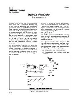


APPLICATION NOTE U-140 resulting in sub-harmonic oscillation. A com-pensating ramp (with slope equal to the induc-tor current downslope) is usually applied to thecomparator input to eliminate this instability. Ina buck regulator the inductor current down-slope equals VJL. With V. constant, as itusually is, the compensating ramp is fixed andeasy to calculate-but it does complicate thedesign. With a boost regulator in a high powerfactor application, the downslope of inductorcurrent equals (V,&$J/L and thus varies con-siderably as the input voltage follows the recti-fied sine waveform. A fixed ramp providingadequate compensation will overcompensatemuch of the time, with resulting performancedegradation and increased distortion.Peak to average current error. The peak toaverage current error inherent in the peakmethod of inductor current control is usuallynot a serious problem in conventional buck-derived power supplies. This is because induc-tor ripple current is usually much smaller thanthe average full load inductor current, and be-cause the outer voltage control loop soon elimi-nates this error.In high power factor boost preregulators thepeak/avg error is very serious because it causesdistortion of the input current waveform. Whilethe peak current follows the desired sine wavecurrent program, the average current does not.The peak/avg error becomes much worse atlower current levels, especially when the induc-tor current becomes discontinuous as the sinewave approaches zero every half cycle. Toachieve low distortion, the peak/avg error must R, (set by the outerloop) represents the desired current programlevel. The voltage across current sense resistor represents actual inductor current. Thedifference, or current error, is amplified andcompared to a large amplitude sawtooth (oscil-lator ramp) at the PWM comparator inputs.The gain-bandwidth characteristic of the cur-rent loop can be tailored for optimum perfor-mance by the compensation network aroundthe CA. Compared with peak current modecontrol, the current loop gain crossover fre-quency, f , can be made approximately thesame, but the gain will be much greater atlower frequencies.The result is:1) Average current tracks the current pro-gram with a high degree of accuracy. This isespecially important in high power factorpreregulators, enabling less than 3% harmonicdistortion to be achieved with a relatively smallinductor. In fact, average current mode controlfunctions well even when the mode boundary iscrossed into the discontinuous mode at lowcurrent levels. The outer voltage control loop isoblivious to this mode change. 2) Slope compensation is not required, but 3-357 APPLICATION NOTE there is a limit to loop gain at the switchingfrequency in order to achieve stability.3) Noise immunity is excellent. When theclock pulse turns the power switch on, theoscillator ramp immediately dives to its lowestlevel, volts away from the corresponding cur-rent error level at the input of the PWMcomparator. The average current mode method can beused to sense and control the current in anycircuit branch. Thus it can control input currentaccurately with buck and flyback topologies,and can control output current with boost andflyback topologies.Designing the Optimum Control LoopGain Limitation at f s : Switching powersupply control circuits all exhibit subharmonicoscillation problems if the slopes of the wave-forms applied to the two inputs of the PWMcomparator are inappropriately related.With peak current mode control, slopecompensation prevents this instability.Average current mode control has a verysimilar problem, but a better solution. Theoscillator ramp effectively provides a greatamount of slope compensation. One criterion fc. It is the firstthing that needs to be considered in optimizingthe average current modecontrol loop.In the following exam-ples, we assume that thepower circuit design hasbeen completed, and onlythe CA compensatioremains to be worked out. U-140 Example 1: Buck Regulator Output Current. The simple buck regulator shown in Fig. 2 hasthe following operating parameters:Switching Frequency, f’ = 100 kHzInput Voltage, V,N = 15 - 30VOutput Voltage, V 0 = 12VOutput Current, I, = 5A (6A O.L.)Inductance, L = 60 PH max. MO @ 30V (100 kHz) = 1.2ASense Resistance, = 0.10 CFp is temporarily omitted. Zero R, is well below the switching frequency. Near f s , the amplifier gain is flat. The overall currentloop has only one active pole (from the induc-tor).The inductor current is sensed through R,. (How this is accomplished will be discussedlater.) The inductor current waveform with itssawtooth ripple component is amplified andinverted through the CA and applied to thecomparator. The inductor current downslope(while the switch is off) becomes an upslope, asshown in Fig. 2. To avoid subharmonic oscilla-tion, this off-time CA output slope must notexceed the oscillator ramp slope. In Fig. 2, theoff-time CA output slope is much less than theoscillator ramp slope, indicating that the CAgain is less than optimum.Calculating the slopes:Inductor Current Downslope = Vo/L = Vs/Ts = Vsf s Where V s is the oscillator ramp p-p voltage, Ts and f s are the switching period and frequency.Fig. 2 - Average Current Mode Control Circuit and Waveforms 3-358 APPLICATION NOTE U-140 The inductor current downslope is translatedinto a voltage across current sense resistor Rs and multiplied by the CA gain, GU This is setequal to the oscillator ramp slope to determinethe CA gain allowed at fs: Applying the values given in the example, andwith Vs of 5Vpp, the maximum GCA at theswitching frequency is 25 (28dB). The currenterror amplifier gain at fs is set to this optimumvalue by making the ratio RJR, = 25.The small-signal control-to-output gain ofthe buck regulator current loop power section(from vcA at the CA output, to vRS, the voltageacross R S ) is:The overall open loop gain of the currentloop is found by multiplying (1) and (2). Theresult is set equal to 1 to solve for the loopgain crossover frequency, f c :Setting the CA gain at the limit found in (1),the crossover frequency will never be less thanone sixth of the switching frequency. (This isexactly the same result reported by Middle-brook [1] for peak current mode control withrecommended slope compensation.) In thisexample, f c is 20 kHz with VI, at 15V (D= .8),and 40 kHz when V,, at 30V (D= .4).Fig. 3 - Buck Waveforms, Optimized GainIf the error amplifier had a flat gain charac-teristic, the phase margin at crossover would be90° -much more than required-and the gainat lower frequencies wouldn’t be much betterthan with peak current mode control. But zero R, Cn placed at 10 kHz, below the minimumcrossover frequency, reduces the phase marginto 63°,and boosts the low frequency gain V,, at 30V and fullload. Note how the amplified and invertedinductor current downslope virtually coincideswith the oscillator ramp, because the CA gainwas set at the optimum level according toEquation (1). Note also that if the CA gain isincreased further, not only will the off-timeslope exceed the oscillator ramp slope, but thepositive excursion may reach the CA compli-ance limit, clipping or clamping the waveform.Pole R, CFP CFz/(CFP+ CFz) s (100 kHz). This pole has onepurpose-to eliminate noise spikes riding on thecurrent waveform, the nemesis of peak currentmode control. The sawtooth CA output wave-form is also diminished, especially the higherorder harmonics, and shifted in phase as shownin Fig. 4. The pole-zero pair (at 100 kHz and10 kHz) reduces the phase margin at crossoverto a very acceptable 45° -see Fig. 5.The reduced amplitude and slopes of the CAwaveform resulting from the 100 kHz polemight suggest that the CA gain could be in- 3-35 APPLICATION NOTE U-140 Fig. 4 - Buck with Additional Pole at f S Fig. 5 - Buck Regulator Bode Plotcreased beyond the maximum value fromEquation (1), but beware-Eq. (1) is valid onlyfor a system with a single pole response at f s ,but with CFP added there are now two activepoles at f s . Experimentally, increasing G, mayincur subharmonic oscillation.Discontinuous Operation. When the loadcurrent I, VI,,, , when ripplecurrent is greatest. In this example, the modeboundary occurs at I, (=IJ of 0.2A when V IN is 15V, and at 0.6A when V IN is 30V.In the discontinuous mode, below the modeboundary, changes in I, require large dutycycle changes. In other words, the power circuitgain suddenly becomes very low. Also, thesingle pole characteristic of continuous modeoperation with its 90° phase lag disappears, sothe power circuit gain is flat-independent offrequency. The current loop becomes morestable, but much less responsive.With peak current mode control in thediscontinuous mode, peak/avg current errorbecomes unacceptably huge. But with averagecurrent mode control, the high gain of the V’& equals the current programming voltage V& fs. The transconductance of theclosed current loop is a part of the outervoltage control loop:The closed loop transconductance rolls offand assumes a single pole characteristic at theopen loop crossover frequency, fs. APPLICATION NOTE fs = 100 kHzInput Volts, v’N = 90 - 270V rmsoutput Volts, & = 380VdcMax. O.L. I IN (@90V) = 12A rms, 17A pkL 0.25mH AIL, AlrN @90V = 3.4A Rs 0.05nThe max. overload line current at min. vlN corresponds to 1080W input. The max. peakoverload 60Hz line current (17A) should-bydesign-correspond to a limit on the currentprogramming signal, I,,. The max peak 100kHzcurrent through the switch and rectifier is 17Aplus one-half 17 + 3.4/2 = 18.7AFig. 6 - Boost Preregulator CircuitThe current downslope occurs when the powerswitch is off:Inductor Current Downslope = (V’ -T/IN)/LWorst case when V IN = 0 : VJL = Vs/Ts = Vs f, Multiply the downslope by Rs and CA gain andset equal to the oscillator ramp slope, thensolve for maximum CA gain:Note the form of Equation (6) is identical tothe buck regulator in (1). Using the values for U-140 this application, the maximum G, is 6.58,accomplished by making RF/RI = 6.58.The small-signal control-to-input gain of thecurrent loop power section (from vGa at the CAoutput, to VRS, the voltage across R,) is:(7Note that (7) is nearly identical to (2) forthe buck regulator, except the gain depends on V. (which is constant), rather than Vl,,, .The overall current loop gain is found bymultiplying (6) and (7). The result is set equalto 1 to solve for the crossover frequency, fc :(8With the CA gain at the limit found in (6), thecurrent loop fc is fixed at fs/6 (16.7 kHz).As with the earlier example, with a flat gainerror amplifier the phase margin at crossoveris 90° — larger than necessary. So zero R, Cm isset at 1/2 of the minimum crossover frequency VCP = fsll2 = 8.33 kHz), providing a lowfrequency boost with an integrator gain of55K/f. Pole R, CFp CFz/(CFp+ Cm) is set at 6times the zero frequency (50 kHz) to eliminatenoise spikes. Together, the zero at 8.33 kHzand the pole at 50 kHz leave a phase margin atcrossover of 40°. Startup waveforms are shownin Fig. 7, and the Bode plot in Fig. 8.Fig. 7 - Boost Regulator Waveforms 3-361 APPLICATION NOTE U-140 Referring back to Fig. 6 — when the currentloop is closed, the voltage across current senseresistor I& equals the voltage across current VRcP. In this case, pro-grammed with a current source I,, the currentgain of the closed current loop is: (9) The closed loop current gain rolls off andassumes a single pole characteristic at the openloop crossover frequency, fs.10 100 1k 10k 100k 1MFig. 8 - Boost Regulator Bode PlotIn a high power factor preregulator applica-tion, the current is programmed to follow therectified line voltage. As the rectified sine wavevoltage and current approaches the cusp at zero,the inductor current becomes discontinuous.Discontinuous operation can occur over a 3-362 APPLICATION NOTE U-140 Fig. 10 - Boost 400Hz Sine Wave Input Current 1. The harmonic components of the rectified400 Hz waveform are at higher frequenciesand closer to the current loop crossoverfrequency where the loop gain is less, com-pared with the 50 or 60 Hz harmonics.The inductor current has difficulty rising offzero because the input voltage is so very lowat that point. So the inductor current lagscoming off zero, then catches up and over-shoots the programmed level. (This effect ismuch worse with peak current mode controlbecause of the large inductor required.)Controlling Average Switch CurrentIn the previous examples, average currentmode control was applied to controlling induc-tor current (buck output current and boostinput current). This is relatively easy becausethe inductor current is mostly DC with only a fs = 100 kHzInput Volts, V,N = 90 - 270V rmsOutput Volts, v0 = 300V dcMax. O.L. IIN = 12A rms, 17A pkL = 0.25mH AIL @9OV = 3.6A R, = The max. overload rms line current at min. V,,,, equates to 1080W input (2160Wpk 60Hz).The max. overload peak 60 Hz line current(17A) should be made to correspond to a limiton the current programming input, IcP. Unlikethe boost converter, the flyback input current ischopped, so the peak 100kHz current through 3-363 APPLICATION NOTE the switch, the inductor, and the rectifier aremuch greater than the 60 Hz peak current-seeFig. 12. The worst case, at low line and max.overload input current is:Add to this one-half ML to obtain the abso-lute max. peak current through the switch,inductor, and rectifier: 24.2 + 3.6/2 = 26A.Compared to the boost converter, the fly-back topology requires higher current andhigher voltage devices and generates a lot moreinput noise because of the chopped waveform.In its favor, the flyback converter can operatewith any input/output voltage ratio, can providecurrent limiting, and input/output isolation.As discussed in the previous example, theboost converter amplifier gain at fS was limitedonly by the criteria that the inductor currentdownslope must not exceed the oscillator rampslope. The power circuit control-to-input cur-rent gain had a simple -1 slope from zero to fS, making it very easy to compensate.But with the flyback converter, the choppedswitch current waveform will be averaged. Thisresults in a lower crossover frequency, f,, andlower gain-bandwidth for two reasons:1. The large amplitude chopped current wave-form must be integrated by the CA. Theupslope of the resulting triangular waveformat the CA output must not exceed the oscil-lator ramp slope. (The inductor currentdownslope is not relevant.)2. There is a zero (conventional left half-plane)in the control-to-input current gain charac-teristic. This zero moves with output currentlevel. Loop gain crossover cannot be muchhigher than the lowest zero frequency.The small-signal control-to-input gain of theflyback current loop power circuit (from vcA atthe CA output, to vRs , the voltage across R, ) is: This is the characteristic of a “normal”zero-a -1 slope with 90° phase lag below fi and flat gain with no phase shift above fi. Thezero frequency may be calculated: (11) Note that the zero moves inversely withinductor current and inductance value. Thiszero has a big effect on loop compensation. Toobtain the best loop response, it is importantthat firni,, be as high as possible, by making theinductance small. Fortunately, with averagecurrent mode control, there is no need toworry about crossing into discontinuous opera-tion. The limit on making the inductance toosmall is when the inductor ripple currentbecomes too large, increasing peak switch andrectifier currents an undesirable amount.Using the specific values of this example, thepower circuit gain is:The minimum zero frequency is 8 kHz,which occurs at 24.2A, the max. overloadinductor current at 90V low line. The gainabove fi is 0.12 (-18.4dB). The power circuitgain is shown in the Bode plot of Fig. 13.Turning now to the current error amplifier(Fig. 11), the chopped input (switch) currentwaveform shown in Fig. 12 flows through R,. The average value of this waveform, choppedat 100 kHz, is compared to the current pro-gram level across R, and amplified. Assumefor the moment that CP,, is zero and C, isshorted. The CA gain in the vicinity of 100kHz is determined by integrator (R,+R,,)CF,. Averaging is accomplished because the DCgain is high, but the 100 kHz rectangularwaveform with its harmonics is amplifiedrelatively little. The rectangular waveform isconverted into a triangular wave as shown inFig. 12. 3-364 (13) APPLICATION NOTE Fig. 12 - Flyback Regulator WaveformsThe optimum CA integtator gain at 100 kHzis the gain at which the maximum CA outputupslope equals the oscillator ramp slope. This isthe same principle used in the previous twoexamples, but in those cases the inductor(whose current was being controlled) did mostof the averaging. The inductor did the inte-gration to provide the triangular ripple currentwaveform and the CA gain was flat in thevicinity of js. But in this flyback preregulatorexample, the chopped switch current is beingcontrolled so the averaging and the triangularwaveshape are achieved by an integratingamplifier.The upslope of the CA output occurs whenthe switch is off and the 100 kHz currentwaveform is at zero. The CA inputs are both atprogram voltage V& . Vc- equates to themax. overload peak 60Hz input current (17A)through R,. Therefore, during the switch “off”time,R = (R,+R& is:The upslope of the CA output is determinedby the current through R, charging CFP: Oscillator Ramp SIope = V s / s = V s js Equating the slopes and solving for CFp: Using the values from this example, andassuming R =10K (R,=9K, R,=lK) :The CA integrator gain may now be calcu-lated and entered in the Bode plot:The compensation circuit as designed so far(with C,, zero and CFZ open) has high loopgain and is very stable only when the inductorcurrent is high, maintaining the power circuitzero near the position shown in Fig. 13, so thatits gain is flat at fc. At lower current levels, thepower circuit zero slides down to the right andFig. 13 - Flyback Regulator Bode Plot APPLICATION NOTE the power circuit gain at f C has a -1 slope. Withthe -1 slope of the CA gain, the overall currentloop gain has a slope of -2 at crossover, andwill ring excessively. It is necessary to add apole-zero pair to the CA gain to reduce theslope to -1 in the vicinity of fc. Offsetting theintegrator gain by a factor of 5, as shown in theBode plot, provides a phase bump which in-creases the actual phase margin to 42°, aslightly underdamped condition (the Bodeapproximation is 31°, as shown).The offset factor of 5 is provided by cm = 4c, =340pF. Cn and CFp in parallelset the integrator gain at low frequencies to37,000/f.The location of the flat portion of the CAgain characteristic is determined by R,. It iseasiest to solve this graphically using the Bodeplot. Ideally, Z1 and P1 should bracket thecrossover frequency. Simply slide the flat por-tion up and down between the integrator slopesuntil its gain is equal (but opposite in sign) to fc In Fig 13, the CAgain in the flat portion is 10 (20dB). This isaccomplished by:The precise value of R, (and fc) is not at allcritical. The phase bump is broad, and the loopresponse is really determined by the integratorgain below fc (37,000/f). Finally, an additional pole RPZCPZ is placed at 100kHz to filter out noise spikes. This polefrequency is too high to significantly affect phase margin at crossover. Referring back to Fig. 11 — when the cur-rent loop is closed, the voltage across currentsense resistor I& equals the voltage acrosscurrent programming resistor v&P Program- med with a current source Icp the current gainof the closed current loop is identical to Eq. 9: U-140 Just as in the previous examples, the closedloop current gain rolls off and assumes a singlepole characteristic at the open loop crossoverfrequency, fs. The moving zero of the flybackpower circuit is hidden within the inner currentloop, and is invisible to the outer voltagecontrol loop. In fact-regardless of the powercircuit topology-with average current modecontrol, the external characteristics of the cur-rent loops are identical: flat gain, rolling offwith a single pole characteristic above the openloop crossover frequency.Example 4: Buck Regulator Input Current:The buck regulator is sometimes used in highpower factor preregulator applications. It canonly function when V0 is less than l&, so theoutput bus voltage must be low. Normally, alow output voltage should be avoided, becausethe bus filter capacitor becomes large andexpensive, but in applications such as telephoneor battery charging this is not a problemand/or there is no choice. With 120V line inputand 48 volt output bus, the input current willdrop to zero for a substantial portion of eachline cycle, each time the instantaneous linevoltage goes below 48V. Third harmonic distor-tion will be 7 - 8% at low line, but the powerfactor of 0.99 is good enough for most applica-tions.Although the flyback topology might be usedin the same low voltage output application, thebuck topology operates with lower inductorcurrent and lower peak current through theswitch and rectifier. Peak voltages on theswitch and rectifier are also much lower. Butthe flyback topology can provide line isolationin the preregulator by using a flyback trans-former instead of simple inductor.The buck circuit can be almost the same asthe flyback circuit of Fig. 11, interchanging theinductor and the rectifier (cathode up).The control loop design procedure is thesame as for the flyback in Example 3. Thebuck regulator has the same left half-planezero. In fact, the power circuit control-to-inputgain equation is identical to Eq. 10 for theflyback circuit. 3-366 APPLICATION NOTE U-140 Controlling Average Rectifier Current Peak current mode control has been usedwith great success in conventional power sup-plies using buck-derived topologies. It workswell because peak current mode control actual-ly controls inductor current, and the inductor islocated in the output of all buck topologies.When boost or flyback topologies are used,peak current mode control functions poorly,because the wrong current is controlled-theinductor current is not in the output. Althoughpeak current mode control eliminates theinductor from the small-signal characteristic ofthe outer loop, the right half-plane zero presentin boost and flyback outputs remains to plagueouter loop compensation.In boost or flyback circuits, the diode is inthe output side, and ideally the diode currentshould be controlled, not inductor current. Thisis no problem for average current mode con-trol. Its integrating current error amplifier canaverage the rectangular diode current waveformin the same way that it averages the switchcurrent in the input of the buck or flybackpreregulators discussed earlier. The right half- vcA at the CA output, to vRs , the voltage across R,) is:The same equation applies to controlling theoutput current of a boost circuit. Note thesimilarity with Eq. 10 for flyback or buck inputcurrent control. In Eq. 16, low frequency gaindepends on rather than V& but moreimportantly, the inductor current It has aminus sign, which represents 180° phase lagabove the zero frequency. This is the character-istic of a right half-plane zero, and it makes theloop compensation much more difficult. It isusually necessary to cross over at a frequencyone half to one fourth of the RHP zero fre-quency in order to cross over with adequatephase margin. This results in lower closed loop Current Sensing One important advantage of having a highgain current error amplifier is that it permits avery small current sense resistor value resultingin low power dissipation. The CA can make upfor the gain lost with the small resistor.In many applications, however, using acurrent sense resistor in the direct path of thecurrent to be measured is not practical. Thetiny value may be difficult to implement,and the power dissipation in a practical sense 3-367 APPLICATION NOTE resistor is too great. Often, the R, circuitlocation is at a large potential difference fromthe control circuit. This is especially a concernwhen current must be sensed on the other sideof the isolation boundary.A current sense transformer (C.T.) canprovide the necessary dielectric isolation andeliminate the need for an extreme low-valueresistor. As shown in Fig. 15, this techniqueFig. 15works well for average current mode controlwhen the current to be sensed and averaged isa pulse which returns to zero within eachswitching period-such as switch current (buckor flyback input current) or diode current(boost or flyback output current). Although“transformers can’t couple DC”, a C.T. doescouple the entire instantaneous current wave-form including its DC component if the core isreset to zero baseline each time the pulse goesto zero.Total reset requires the same volt-seconds(of opposite sign) that were applied to “set”the core. At duty cycles approaching 1.0-whichcan occur temporarily with most topologies-thetime available for reset may be only a tinyfraction of the switching period. Achieving totalreset in a short time requires a large backswingof voltage across the C.T., so don’t use lowvoltage diodes to couple the C.T. to R,. With a boost converter controlling inputcurrent in a high power factor preregulatorapplication, a current sense resistor easily tiesin directly with the control circuit, as shown inFig. 6. Nevertheless, many designers would R, value. However, since the input current ofa boost converter is the inductor current, theinput current never goes to zero when operat-ing in the continuous mode. Therefore, a C.T..can’t be used to sense input current of a boostconverter because the DC value is lost, and theC.T. cannot reset-it will saturate. The sameproblem occurs in a buck regulator circuit,where the C.T. can’t directly sense averageoutput (inductor) current.The answer to this problem is to use twC.T.s–one sensing switch current, the othersensing diode current. By summing their out-puts as shown in Fig. 16, the true inductorcurrent is reconstituted. Each C.T. has plentyof time to reset.Fig. 16Using Current Sense Transformers: R, is precisely IPRI/N, but as time passes, thesecondary current drops off more rapidly thanit should, This effect is called “droop”. It isusually not a problem if certain precautions areobserved. The amount of current droopthrough the current sense resistor can becalculated:where N is the turns ratio, V’ the voltageacross the secondary, L, the secondary induc-tance and At is the max. pulse width. As the 3-368 APPLICATION NOTE a equation shows, droop is minimized by maxi-mizing secondary inductance-use the largestyou can get. Don’t use a large R, value to 0.0250 sense resistor shown. Using the PulseEngineering #51688 current sense inductorwith one turn primary, the turns ratio is 1:200.Secondary inductance is 80 mH. The 24A max. 1On senseresistor will have a max. voltage of l.3V sent tothe CA, and the max. secondary voltage includ-ing diode forward drop is 2.0V. The maximumpulse width is 7.02µsec.Applying these values to Eq. 17:Only 35mA droop out of 24A isn’t bad!When two C.T.s are used-one on either sideof isolation boundary-their turns ratios must beproportioned the same as the power transform-er pri/sec turns ratio so that currents through Rs R, givenearlier in this paper assume the sense resistoris measuring current directly. When using acurrent sense transformer, reflect the actual R, on the C.T. secondary side into the primary by substituting RsNJNs. UNITRODE CORPORATION 7 CONTINENTAL BLVD.. MERRIMACK, NH 03054 TEL. (603) 424-2410 l FAX (603) 424-3460 References S. Hsu, A. Brown, L. Rensink, R.D. Middle-brook,“Modelling and Analysis ofSwitching DC-to-DC Converters in Con-stant Frequency Current ProgrammedMode, “IEEE PESC Proceedings, 1979[2] R.D. Middlebrook, “Topics in Multiple-Loop Regulators and Current-Mode Pro-gramming”IEEE PESC Proceedings,June 1985 3-369 IMPORTANT NOTICETexas Instruments and its subsidiaries (TI) reserve the right to make changes to their products or to discontinueany product or service without notice, and advise customers to obtain the latest version of relevant informationto verify, before placing orders, that information being relied on is current and complete. All products are soldsubject to the terms and conditions of sale supplied at the time of order acknowledgement, including thosepertaining to warranty, patent infringement, and limitation of liability.TI warrants performance of its semiconductor products to the specifications applicable at the time of sale inaccordance with TI's standard warranty. Testing and other quality control techniques are utilized to the extentTI deems necessary to support this warranty. Specific testing of all parameters of each device is not necessarilyperformed, except those mandated by government requirements.CERTAIN APPLICATIONS USING SEMICONDUCTOR PRODUCTS MAY INVOLVE POTENTIAL RISKS OFDEATH, PERSONAL INJURY, OR SEVERE PROPERTY OR ENVIRONMENTAL DAMAGE (ªCRITICALAPPLICATIONSº). TI SEMICONDUCTOR PRODUCTS ARE NOT DESIGNED, AUTHORIZED, ORWARRANTED TO BE SUITABLE FOR USE IN LIFE-SUPPORT DEVICES OR SYSTEMS OR OTHERCRITICAL APPLICATIONS. INCLUSION OF TI PRODUCTS IN SUCH APPLICATIONS IS UNDERSTOOD TOBE FULLY AT THE CUSTOMER'S RISK.In order to minimize risks associated with the customer's applications, adequate design and operatingTI assumes no liability for applications assistance or customer product design. TI does not warrant or representthat any license, either express or implied, is granted under any patent right, copyright, mask work right, or otherintellectual property right of TI covering or relating to any combination, machine, or process in which suchsemiconductor products or services might be or are used. TI's publication of information regarding any thirdparty's products or services does not constitute TI's approval, warranty or endorsement thereof. 1999, Texas Instruments Incorporated