
Snehal Shetye Rob Mauck Function of the Skeleton Support and protection for internal organs Attachment sites for muscles allowing movement of limbs Structure support for bone marrow and blood vessels ID: 918257
Download Presentation The PPT/PDF document "Mechanically Testing Bone Tissue" is the property of its rightful owner. Permission is granted to download and print the materials on this web site for personal, non-commercial use only, and to display it on your personal computer provided you do not modify the materials and that you retain all copyright notices contained in the materials. By downloading content from our website, you accept the terms of this agreement.


Slide1
Mechanically Testing Bone Tissue
Snehal Shetye, Rob Mauck
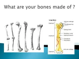
Slide2Function of the Skeleton
Support and protection for internal organs
Attachment sites for muscles allowing movement of limbs
Structure support for bone marrow and blood vessels
Mineral reservoir for calcium and phosphorus
Endocrine organ
Osteocalcin
FGF23
Slide3Adaptation to Load
G.H. von Meyer’s trabecular bone architecture in human femur (1867)
Principal stress trajectories of
Culmann’s
crane and human femur (1870)
Slide4Bone material property (mesoscale)
Tension/Compression Test
Test region
Extensometer arms firmly attached with rubber bands
Bone ends embedded in metal end caps
Testing machine slowly applies force to specimen
Force
Deformation
Slide5Bone material property (microscale)
Bone micropillar manufactured by focused ion beamUniaxial compressionStress-Strain curveCompression test
Stress
Strain
Slide6Bone material property (nanoscale)
Birkovich tipNanoindentation
Slide7Cortical bone
Load Response of Bone
Slide8Trabecular bone
Load Response of Bone
Slide9Ulnar overloading
Non-invasive ACL ruptureTibial overloadingIn Vivo loading of bone
Slide103-point Bending
3-point test
Load (F)
Slide11Shear and Moment Diagram
Maximum moment at center point of beam
Slide124-point Bending
4-point test
Load
Slide13Shear and Moment Diagram
Maximum moment spans distance between top actuators
Slide14Maximum Flexural Stress
Here,
is 2
nd
moment of inertia,
= moment applied at middle of specimen,
= distance from center of specimen to convex surface
Elastic Modulus (for 3-point bending)
(for 4-point bending)
Here,
is deflection at max. force,
is length between bottom supports, and
is max. force
Bending Stiffness
Slope of linear region from force-displacement curve
Parameters
Tension
Compression
Slide15Laws of static mechanics:
Sum of all forces
Sum of all moments at a single point
These two equations will resolve the unknown reaction forces at the bottom supports
Moment at any point can now be calculated
3-point Bending:
4-point Bending
How do we calculate
?
Slide16This is difficult for biological specimens
For boneObtain uCT scans of mid-shaftWe have a custom MATLAB code that calculates
for any chosen axis (Bending Buddy)
This code also estimates
by fitting circle to bone cross-section and obtaining equivalent radius
How do we calculate
?
Slide17Measure length of all your samples to determine proper support spacing
3-point bending not recommended for fractured bone4-point bending is generally always recommended over 3-point unless tissue is too smallTorsion tests work well for fractured specimensMost ideal to test all samples on same day (day-to-day variation in test setup can influence results)Keep orientation constant for all samples!Find a stable orientation such that bone does not rotate while being loaded
Stuff to Consider
Slide18Example
4-point bend setup
Slide19Failure modes in bone
Slide203-pt or 4-pt bend tests work well for intact specimens
Fractured samples3-pt test will cause significant stress concentrations at the contact pointUsually that is where the fracture/callus isDefinitely not recommended4-pt test loading points should span the healing siteDifficult to achieve on mouse femora/tibiae
Cannot control size and location of fracture callus
Torsion
Usually have unobstructed access to epiphysis
Only test that evaluates the entire free length of the bone
Does need 6-dof fixation at the termini
Takes longer for prep and setupWhen to use torsion tests?
Load (F)
Load
Slide21Torsion testing
Slide22Polar Moment of Inertia
- perpendicular axis theorem
Obtain
and
from Bending Buddy
Requires
uCT
scan for each sampleDon’t use default output from uCT
Torsion Parameters
Slide23Shear modulus
Parameters we can reportMax. torqueAngular rotation at max. torqueTorsional stiffness
Shear Modulus (
)
Torsional Rigidity (
)
Where
is max. torque applied, is length of specimen being tested, and is twist (in radians) at max. torque Things to rememberExpect a spiral fractureMake sure to take a gauge length image to obtain And a scale image!If testing fractured samples, each sample needs to be mostly straight and vertical
Polar moment of inertia
Slide24Torsion Testing